Notice. New forum software under development. It's going to miss a few functions and look a bit ugly for a while, but I'm working on it full time now as the old forum was too unstable. Couple days, all good. If you notice any issues, please contact me.
Cyber Senior Member Joined: 13/01/2019 Location: UkrainePosts: 161
Posted: 06:10pm 30 Jun 2022
Copy link to clipboard
Print this post
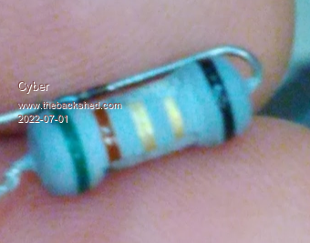
Hello. This will sound strange, but I can't identify resistor value. Color stripes are: green, brown, golden, golden, black. In all manuals I checked golden stripes can't be in the middle, so I'm confused. Please help.
Cyber Senior Member Joined: 13/01/2019 Location: UkrainePosts: 161
Posted: 06:42pm 30 Jun 2022
Copy link to clipboard
Print this post
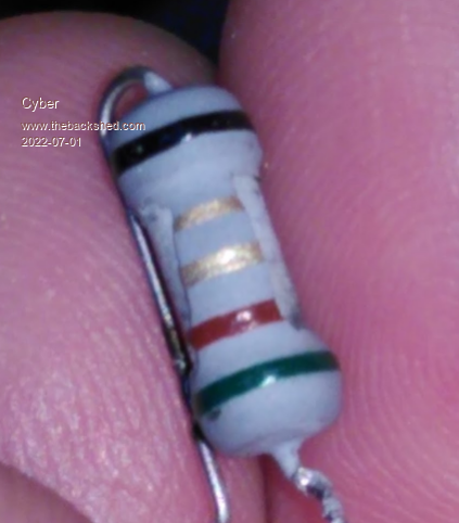
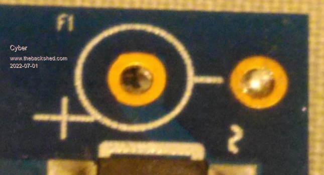
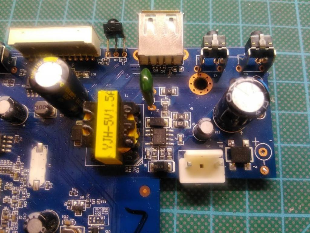
Here are this resistor photos. Also I notice that it is marked as F1 (fuse?) on PCB which is also odd.
mab1 Senior Member Joined: 10/02/2015 Location: United KingdomPosts: 152
Posted: 06:51pm 30 Jun 2022
Copy link to clipboard
Print this post
I was thinking- is it actually a resistor? Is it in a part of the circuit where a fuse woukd make sense?
The phrase fusible resistor also springs to mind, but I'm not very knowledgeable on what the colour code would mean.
Cyber Senior Member Joined: 13/01/2019 Location: UkrainePosts: 161
Posted: 07:05pm 30 Jun 2022
Copy link to clipboard
Print this post
Thank you for hint! Here is what I googled: "If an additional fifth band is black, the resistor is wirewound resistor. If an additional fifth band is white, the resistor is fusible resistor."
Looks like I have wirewound resistor.
Cyber Senior Member Joined: 13/01/2019 Location: UkrainePosts: 161
Posted: 02:59pm 01 Jul 2022
Copy link to clipboard
Print this post
So it looks like it is 5.1 Ohm wirewound resistor. Checked nearby shops, not many have it, looks like it is not a popular component. But at least I know what I need now. Thank you again, mab1!
wiseguy Guru Joined: 21/06/2018 Location: AustraliaPosts: 995
Posted: 03:18pm 01 Jul 2022
Copy link to clipboard
Print this post
This may be an obvious comment but if that resistor is open circuit, it would usually fail for a reason, it passed too much current due to some issue or fault. If you haven't looked further to check other surrounding parts for issues a new resistor may end up with the same fate.
It is also possible a big mains spike caused it to look like that. Are you sure it is open circuit - and not just looking a bit sad - there doesn't seem to be enough blackness making me wonder if it still might read 5R1, this would not be the first time a part looking dead/abused still works - sorry if this is an insulting question to you.
"If an additional fifth band is white, the resistor is a fusible resistor." I just learned something new too !! Have used/replaced many but never noticed a white band..... I am guilty of usually just confirming their value with a meter and ignoring the bands.
These days some resistors with 5 or 6 bands can make a sensible sounding value reading from either end so checking with a meter is a good thing. Edited 2022-07-02 01:20 by wiseguyIf at first you dont succeed, I suggest you avoid sky diving.... Cheers Mike
pd-- Senior Member Joined: 11/12/2020 Location: AustraliaPosts: 122
Posted: 08:51am 02 Jul 2022
Copy link to clipboard
Print this post
I think its a fuse. 1 its labeled F1 on the PCB 2 it appears to connect to the ac side of a bridge rectifier
As for the value you will need to look at the components its protecting and the devises rated load. every manufacturer seems to have had there own take on color codes on old axial fuses modern components have there values printed
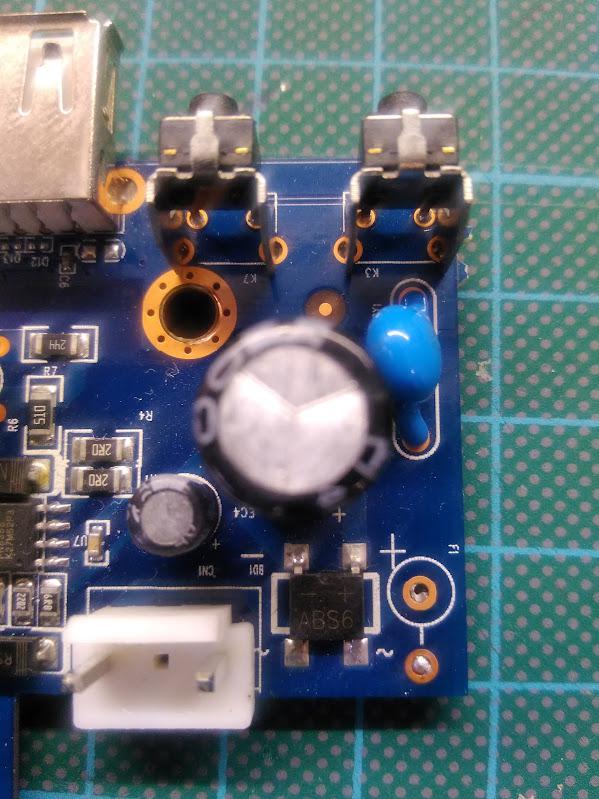
post up a circuit of the next 1/6 dozen components after F1
Pete Locke Senior Member Joined: 26/06/2013 Location: New ZealandPosts: 178
Posted: 09:54pm 02 Jul 2022
Copy link to clipboard
Print this post
If it's in the mains input side, it's almost certainly a metal oxide fusible resistor. Very common on low power boards. What is the unit it came from? Also, there should me a data plate (sticker) indicating input power. Cheers Pete'.
Cyber Senior Member Joined: 13/01/2019 Location: UkrainePosts: 161
Posted: 04:17am 03 Jul 2022
Copy link to clipboard
Print this post
Yes, it is open circuit. And I understand it blowed for a reason. But I also know that sometimes those reasons are not going to repeat, if I replace the part. So I plan to replace this part, and see how it works. If it blows again, then I would know there is some other reason for failure.
Cyber Senior Member Joined: 13/01/2019 Location: UkrainePosts: 161
Posted: 04:20am 03 Jul 2022
Copy link to clipboard
Print this post
Cyber Senior Member Joined: 13/01/2019 Location: UkrainePosts: 161
Posted: 04:25am 03 Jul 2022
Copy link to clipboard
Print this post
It is Romsat TR-9020HD DVB-T2 TV receiver. There is no plate or stcker idicating input power. I think this device is too cheap to have that.
Cyber Senior Member Joined: 13/01/2019 Location: UkrainePosts: 161
Posted: 04:33am 03 Jul 2022
Copy link to clipboard
Print this post
On of the legs of the failed "resistor" goes directly to AC power input. So it does look like it works as a fuse. This is the first time a see something that looks like a regular resistor to act like a fuse. )
Cyber Senior Member Joined: 13/01/2019 Location: UkrainePosts: 161
wiseguy Guru Joined: 21/06/2018 Location: AustraliaPosts: 995
Posted: 05:32am 03 Jul 2022
Copy link to clipboard
Print this post
First component I would check is the diode to the left hand side of the transformer in the second picture, it may be shorted. The second item is to check the bridge diode next to the fusible resistor. The little 7 pin switchmode IC sees to have something on the top of the body just near pin 6 - is that a small crack (if it is that will be the answer too). Good luck with it!If at first you dont succeed, I suggest you avoid sky diving.... Cheers Mike
rogerdw Guru Joined: 22/10/2019 Location: AustraliaPosts: 795
Posted: 05:41am 03 Jul 2022
Copy link to clipboard
Print this post
Well I'll stick my neck out and tell you it's a fusible resistor.
Apart from checking the bridge rectifier, P/S IC and closeby diodes for shorts, I'd replace it (shield my eyes) and see what happens.
And if I was in a hurry and didn't have any fusible resistors, I'd stick a sensibly sized fuse or even a standard resistor temporarily, to see if that's all that's wrong.
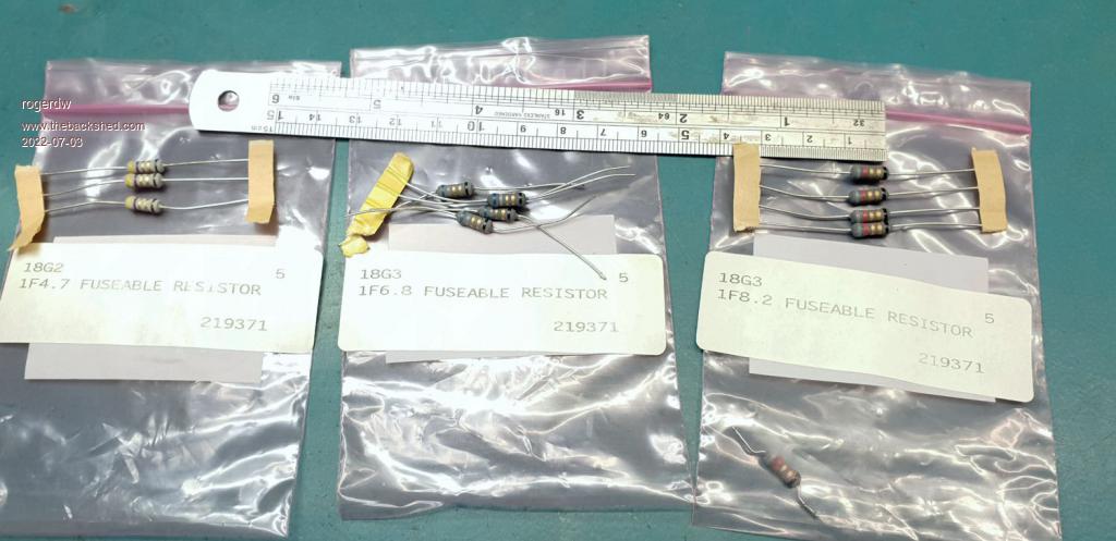
I have a drawer full of 1/2 watt, 1, 2 and 3 watt fusible resistors from an earlier work life.
The photo shows the colours and the related values and these too have two gold lines and then a final black. These are 1 watt resistors and the bodies are close to 10mm long
Cheers, Roger
phil99 Guru Joined: 11/02/2018 Location: AustraliaPosts: 1781
Posted: 07:53am 03 Jul 2022
Copy link to clipboard
Print this post
An old servicing tip. Temporarily wire up a 240V incandescent lamp in place of the fuse. Choose one with a wattage that will allow enough current for the circuit to run. If there is a fault it will prevent further damage while you diagnose the cause.
In switch-mode supplies it is often the HV switching transistor or IC that is short circuit. If the IC has failed check the main filter capacitor, if it's value has fallen too low or it's ESR has gone too high it may be the cause.
Take extreme care when testing live circuits!
"The little 7 pin switch-mode IC seems to have something on the top of the body just near pin 6 - is that a small crack " Zoomed in on that but the resolution isn't good enough to tell if it is a crack, soot mark or just part of the logo. Need a macro pic to be certain. . Edited 2022-07-03 18:30 by phil99
pd-- Senior Member Joined: 11/12/2020 Location: AustraliaPosts: 122
Posted: 09:19am 03 Jul 2022
Copy link to clipboard
Print this post
Any thunder storms around at the time of failure , you may find sum burn tracks around the RF end of the devise.
it is probably 5.2 ohm the gold / gold being x10-1 and 5% tolerance you would need to measure its diameter and length to confirm wattage but 1w seems about right
Pete Locke Senior Member Joined: 26/06/2013 Location: New ZealandPosts: 178
Posted: 08:12am 04 Jul 2022
Copy link to clipboard
Print this post
As Phil said, replace it with a low wattage lamp. Easy to see a short without extra circuit stress. Do an ohm reading across the main smoothing cap prior to see if there's a bit of a give away there regarding a primary side short. I have a home made interrupted phase tappon plug with a 70w lamp for just such events, it will tell you a story before your multimeter warms up :-)