
|
|
Forum Index : Electronics : MPPT Charge Controller built
| Author | Message | ||||
Revlac Guru Joined: 31/12/2016 Location: AustraliaPosts: 1153 |
This is the fuse holder setup for the charge controller, 2 fuses for the solar input and through the trip breaker (work in progress) ,then out of the charger with the positive through a 50A fuse, or bigger if required. I have 2 others setup similar to this and its worked well for years, I like the look of the older style fuse holders.  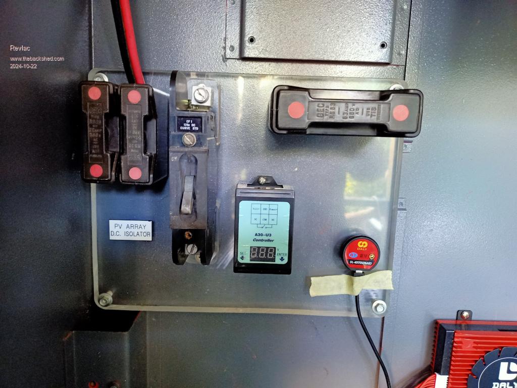 Cheers Aaron Off The Grid |
||||
| Revlac Guru Joined: 31/12/2016 Location: AustraliaPosts: 1153 |
Some progress, just done a bit more wiring, still calibrating a few things but so far it seems to be almost ready to go I connected a small 48v battery and a 80v solar panel for some testing and its looking good.  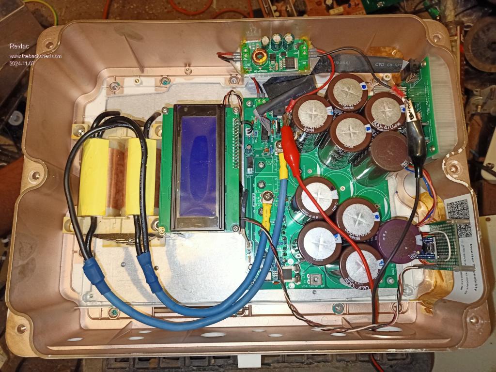 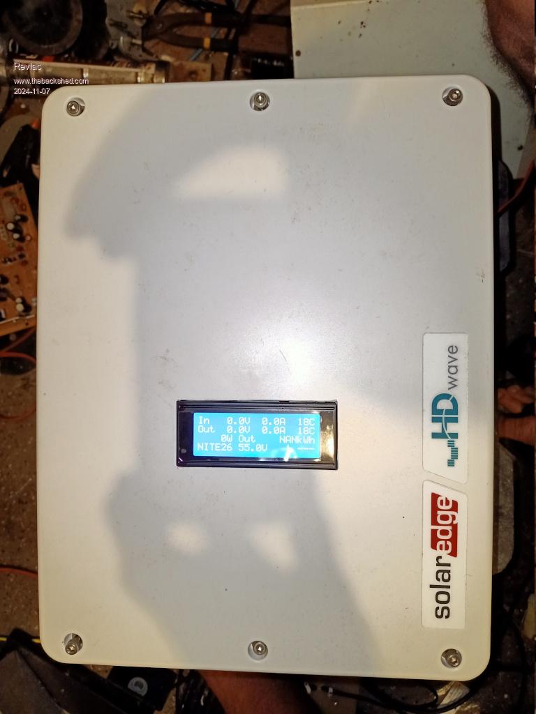 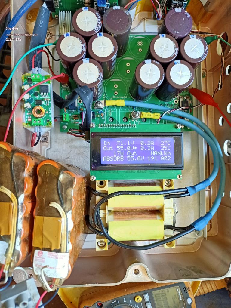 Still have to put it in the cabinet and wire in the battery cables and solar cables in through the bottom and a bit of a tidy up, hopefully have it connected tomorrow ready for some decent power. Cheers Aaron Off The Grid |
||||
| Revlac Guru Joined: 31/12/2016 Location: AustraliaPosts: 1153 |
I have made a few changes to the charge controller, added a small momentary switch at the bottom, and now running the code from page 1, still testing, so far the inductor and heat sink has been surprisingly cool, much cooler than the other commercial units running. 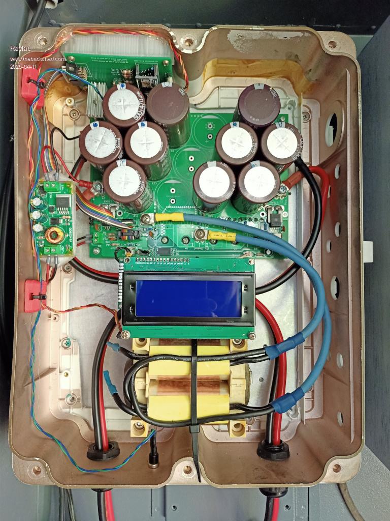 Also running the nano and wiseguy LCD PCB under the screen and running the "Nano_LCD_MPPT" by KeepIS.  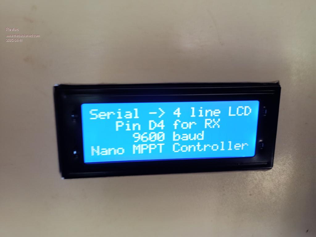 Cheers Aaron Off The Grid |
||||
| KeepIS Guru Joined: 13/10/2014 Location: AustraliaPosts: 1877 |
 I'm feeling guilty, I must get back to finishing my charge controller boards, very nice job. I'm feeling guilty, I must get back to finishing my charge controller boards, very nice job.I like that case . Edited 2025-04-11 11:00 by KeepIS NANO Inverter: Full download - Only Hex Ver 8.1Ks |
||||
| Revlac Guru Joined: 31/12/2016 Location: AustraliaPosts: 1153 |
Yesterday just before lunch, checked the Inverter and charge controller on the way past and noticed the CC screen readout looked a bit funny, the first and second line appeared to have swapped places sort of, and the next 2 lines, well not sure about that. I think it was still working but little power out and the unit was a little above ambient temp? 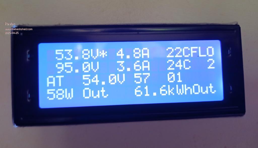 Switched it off for a bit then back on and it reset back to normal. 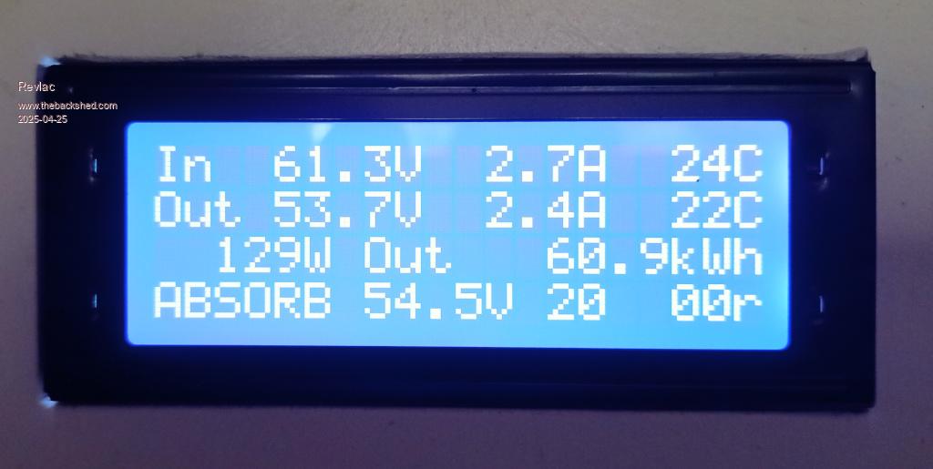 Cheers Aaron Off The Grid |
||||
| KeepIS Guru Joined: 13/10/2014 Location: AustraliaPosts: 1877 |
If it does it again, could you try unplugging the LCD Nano or resetting the LCD Nano, just in case the problem is the LCD code I sent you. NANO Inverter: Full download - Only Hex Ver 8.1Ks |
||||
| rogerdw Guru Joined: 22/10/2019 Location: AustraliaPosts: 906 |
I have four of these mppts in the one assembly and because I haven't finished the front cover yet, the displays are just hanging out the front. On one of them the display consistently freezes or displays something silly and I have got used to pressing the reset button on the LCD Nano. It resets easily enough and carries on till the next time. In my case, I believe the mppt is still functioning properly, it's just the display that hangs up. I really do need to address it though. Cheers, Roger |
||||
| KeepIS Guru Joined: 13/10/2014 Location: AustraliaPosts: 1877 |
I'll dig up Poidas original LCD code and change pin configurations to match wiseguys LCD PCB for you. NANO Inverter: Full download - Only Hex Ver 8.1Ks |
||||
| KeepIS Guru Joined: 13/10/2014 Location: AustraliaPosts: 1877 |
Here is the original MPPT LCD code with pin configuration set for wiseguys Nano LCD PCB. Poida LCD for WG_LCD Have not tested  should work should work NANO Inverter: Full download - Only Hex Ver 8.1Ks |
||||
| Revlac Guru Joined: 31/12/2016 Location: AustraliaPosts: 1153 |
The LCD has been running great for a while until the weekend it decided to mess up a little, I removed the MPPT controller cover to try the reset switch and must has touched the PCB and moved the header pins in its socket, and the Lcd come up with jumbled characters and then restarted correctly, so I thought I should make up a bracket to hold the Nano PCB Firmly to the LCD so nothing can be moved of bumped, Solved I thought..........Now it froze and messed up several times after doing this, I did manage to press the reset button without touching the nano header pins at the nano, and it reset correctly, So No problem with the LCD code its working fine,  I may have to put in a new header socket as the pins may not contact inside the socked sometimes, giving the display bad data......thats my theory... I may have to put in a new header socket as the pins may not contact inside the socked sometimes, giving the display bad data......thats my theory... The MPPT kept running perfectly well throughout, no problem at all, the MPPT is doing its job well, over 100Kwh's all ready EDIT, UPDATE, Well still not sure about the header pins and socket, its more like capacitive touch and the LCD resets when I tried to get round the back to the reset switch, I have taken a short video of it as it happened going to check for any bad solder joints. Edited 2025-05-06 19:41 by Revlac Cheers Aaron Off The Grid |
||||
| The Back Shed's forum code is written, and hosted, in Australia. | © JAQ Software 2025 |
