Notice. New forum software under development. It's going to miss a few functions and look a bit ugly for a while, but I'm working on it full time now as the old forum was too unstable. Couple days, all good. If you notice any issues, please contact me.
sunnypower46 Newbie Joined: 09/12/2021 Location: United StatesPosts: 24
Posted: 03:39am 19 Aug 2022
Copy link to clipboard
Print this post
I have my rewound PJ8000 tranny hooked up and running with my EGS002 PJ8000 power board, but the crystal frequency (60 Hz) is not stable. Huh?
When AC coupled via my microinverters, they won't stay married up; dropping off line then restarting 5 minutes later only to shortly drop off again.
The waveform and voltage off the tranny are good, but the frequency quickly jumps around between 60.1500Hz and 60.2300Hz. Apparently the microinverters see this as an unstable grid and won't play along.
For comparison, I swapped to my remaining original PJ8000 for a microgrid. The coupling was stable and the PJ was solid at 60.0000Hz. So, works great!
Thinking maybe the EGS002 might have a power supply issue or EMI pickup problem, I removed it and installed it into my desk testing board via the EGS002 testing procedure outlined in the manual. I used a 24 volt lipo battery source and appropriate 5 and 12 volt regulators for power, and no potential EMI sources nearby.
My scope gave the same unstable frequency results, but otherwise a healthy functioning board.
Tried three other EGS002 boards, same result. All these boards are new releases dated 20210501, same basic circuit, part locations and pinouts.
Maybe they sourced new crystals not intended for use with the original 22pf load capacitors? I'll have to pad the crystal with more pfs to get the frequency down. Not certain that will cure the instability.
I've ordered more crystals from different supplier and a trimmer capacitor.
I'm curious if anybody has an older (2015?) EGS002 version to check its frequency stability and accuracy.
Any other suggestions are most welcome.
phil99 Guru Joined: 11/02/2018 Location: AustraliaPosts: 3317
Posted: 07:48am 19 Aug 2022
Copy link to clipboard
Print this post
I have no idea if this is relevant to your inverters but some inverters test for a proper grid connection by briefly pulling the frequency up and down a small amount. When connected to the grid the actual frequency cannot change, instead the power factor goes lagging / leading. If the frequency does move it assumes there is no grid, disconnects and tries again later.
noneyabussiness Guru Joined: 31/07/2017 Location: AustraliaPosts: 527
Posted: 08:25am 19 Aug 2022
Copy link to clipboard
Print this post
I know someone had a issue with the crystal on the egs002 not having the little plastic separator between the board and the actual crystal... was earthing on the case of it... maybe check that and also the soldering job..
oh and also check the " load " caps on the crystal's output.. may be out causing this issue..I think it works !!
sunnypower46 Newbie Joined: 09/12/2021 Location: United StatesPosts: 24
Posted: 12:07am 20 Aug 2022
Copy link to clipboard
Print this post
Thanks, @phil99 & noneyabussiness.
I learned something new re the microinverter to grid connection process. Appreciate you sharing that. But, the frequency instability occurs even when using only the EGS002 test setup -- no grid connection, just free running on the test bench. And the accuracy is off. All three spare boards the same.
I removed the existing crystal from an EGS002. There was no plastic separator. Doesn't look like they ever planned for one. The case isn't accidentally or intentionally grounded. I've seen other product boards where they deliberately ground the crystal case. Probably has an effect on loading capacitance, if grounded. The onboard crystal loading capacitors are soldered in place, appear ok. If they're off value, frequency accuracy could suffer, but instability? Hope it's not something in the 8010 chip. Scope waveforms were clean, appropriate and stable. So, ????.
I have different styles of 12.0000 Mhz crystals on order. I'll post the results of swapping them in later.
Anyone using these 20210501 version boards on 60Hz should check the actual frequency of their inverter. As a standalone unit, they probably work ok except for frequency sensitive equipment. Most stuff won't care. My microinverters definitely care.
sunnypower46 Newbie Joined: 09/12/2021 Location: United StatesPosts: 24
Posted: 04:16am 27 Aug 2022
Copy link to clipboard
Print this post
Received new crystals and installed same. Two different styles. Existing compact type (HC-49S) and the four times larger size (HC49/U). Both crystals oscillate with the 8010 chip, but the 60 Hz frequency output of the board in test mode is still slightly high and unstable. So, I conclude the problem is not with the actual crystals.
Still waiting arrival for the trimmer capacitor to dial down the frequency, but not hopeful that is the source of the instability.
My next attempt is to feed the 5v and 12v board inputs with dedicated battery packs, no buck converters or voltage regulating devices. This should rule out any power supply ripple or interference on the dc inputs as a cause.
If that doesn't fix the issue, I guess I'll attempt replacing the 8010 on the board with something from a different vendor. That should be fun! Maybe the frequency scaling circuitry is not functioning right in the EGS002 batch I bought.
I was really hoping someone would scope the output of their EGS002 inverter and report their unit was stable and on frequency. Right now I'm losing confidence in the driver board and the whole 8010 based inverter concept. If I can't create a stable local grid for my microinverters (like my PJ8000 does), I'm not sure what direction I'll go next.
noneyabussiness Guru Joined: 31/07/2017 Location: AustraliaPosts: 527
Posted: 07:00pm 27 Aug 2022
Copy link to clipboard
Print this post
My eg8010 based mini grid has been stable for many years ( as has others).. ( 50hz mind you) .. I have at this moment 4 GTI's synced to it .. they are usually incredibly stable...
its a shame you are experiencing this.. maybe try some different egs002 boards as , as you said , you may have got a dodgy batch...I think it works !!
sunnypower46 Newbie Joined: 09/12/2021 Location: United StatesPosts: 24
Posted: 03:41pm 30 Aug 2022
Copy link to clipboard
Print this post
Tried pure power dedicated battery packs for 5 and 12vdc inputs. Same frequency stability issues. So, not crystals or power supplies related
Ordered 8010 chips for direct replacement on existing boards to see what that might change. Will be a couple of weeks before I receive them.
I may switch one board to 50Hz and check it in the test setup mode per data sheet. Maybe the 60Hz option on the board was an afterthought and not tested as fully?
Perhaps 8010 based inverters are more "hashy" than my original PJ8000 and a low pass filter is needed. Most of the commercial line filters I've looked at don't offer much attenuation below 150kHz, so worth the trouble?
tinyt Guru Joined: 12/11/2017 Location: United StatesPosts: 561
Posted: 02:18pm 31 Aug 2022
Copy link to clipboard
Print this post
I have an EGS002 controlled Inverter set for 60 Hz, and I scope'd the AC output. I set the range low to overdrive the scope input so that the sine wave edges are almost vertical. Then I used the built in cursors and positioned X1 to a zero crossing falling edge and X2 to the next zero crossing falling edge. It showed a frequency of 60.10 Hz. Maybe, it is not accurate enough.
Here is the complete inverter waveform.
I did the same to the Āutility power line and I got the same result of 60.10 Hz.
And here is the complete utility power line waveform.
As I said it might not be accurate enough due to manual cursor positioning and scope calculation resolution. A better way is to use a frequency counter.
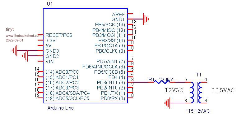
Maybe you can use an arduino just to compare the zero crossing timings of the inverter and the utility power. Something like this plus some sketch to start/stop one of the arduino timers:
Edited 2022-09-01 00:48 by tinyt
sunnypower46 Newbie Joined: 09/12/2021 Location: United StatesPosts: 24
Posted: 08:33pm 02 Sep 2022
Copy link to clipboard
Print this post
Thanks, tinyt.
My waveform looks the same as yours. No observable discontinuities. My Siglent scope expresses frequency out to three decimal places and seems to update every 1-2 seconds. It jumps between 60.1xx and 60.2xx+, regardless where I put the trigger.
I'm going to change the EGS002 frequency jumper and rescope it at 50Hz to compare.
Somewhere in the house a frequency counter is playing hide & seek. It's winning so far.
I don't speak Arduino, but find them interesting. No time to play now, though.
New 8010 chips are in transit and I have a line filter arriving soon.
As I write this, my PJ8000 is synced up to ten Enphase IQ7+ and six NEP microinverters. The system is running steady at 60.000 Hz offgrid on the scope.
Come on little EGS002, get with the program . . . . .
phil99 Guru Joined: 11/02/2018 Location: AustraliaPosts: 3317
Posted: 10:50pm 02 Sep 2022
Copy link to clipboard
Print this post
Adding another layer of complication, might it be a firmware problem rather than hardware? 0.1 Hz steps look like it is testing a grid connection even though you are not in that mode.
sunnypower46 Newbie Joined: 09/12/2021 Location: United StatesPosts: 24
Posted: 08:46pm 06 Sep 2022
Copy link to clipboard
Print this post
@phil99
A guess a firmware issue is certainly a possibility. When new 8010s arrive, maybe that will tell me something. Or they will be flashed the same version, then nothing learned.
I switched the current board I have to 50Hz operation in the testing mode. It puts out 50.1 to 50.2 Hz, with similar instability.
I also recall reading (as you mentioned earlier, too) when microinverters are used in grid tie mode, they normally try to push the grid frequency as part of the sync process. BTW, the attempt to pull the frequency down with a trimmer capacitor failed. If I'd have done some research first, I'd have learned that it wasn't possible to pull a crystal frequency that far.
I'm getting ready to install the line filter I recently received. Maybe the microinverters will benefit from some cleanup of the microgrid stimulus. Perhaps the power line communication (setup profile/monitoring) feature is being confused by line noise.
analog8484 Senior Member Joined: 11/11/2021 Location: United StatesPosts: 204
Posted: 05:12pm 15 Sep 2022
Copy link to clipboard
Print this post
Interesting that you get better AC coupling with PJ.
What grid profile are you using on the iQ7's? You might be able to change to a grid profile with wider frequency tolerance.
sunnypower46 Newbie Joined: 09/12/2021 Location: United StatesPosts: 24
Posted: 04:26am 16 Sep 2022
Copy link to clipboard
Print this post
My IQ7+ micros are pre-configured to work on the US grid system (or system in the country it is purchased). The user can't adjust the profile. Certified installers are given some limited additional privileges to make adjustments, but operating safety when tied to the grid is a top priority.
I'll take this opportunity for a follow up update. I swapped out the onboard 8010 with a replacement. Same issue, frequency not stable. I noticed the PJ control board uses a crystal close to 5Mhz, so not as much dividing down to 60Hz. Maybe a factor.
I'm going to see if the line filter has any effect next.
analog8484 Senior Member Joined: 11/11/2021 Location: United StatesPosts: 204
Posted: 04:27pm 16 Sep 2022
Copy link to clipboard
Print this post
Yes, safety is important but the default Enphase grid profile is set to IEEE1547 which is not really optimized for CA (I believe that's your location). ĀThere are also CA Rule 21 grid profiles from Enphase that are perfectly safe and compliant for CA and have wider tolerances. ĀYou do need admin access to Envoy to change however. ĀIf you don't have admin access then your installer should. Edited 2022-09-17 02:29 by analog8484
noneyabussiness Guru Joined: 31/07/2017 Location: AustraliaPosts: 527
Posted: 07:23pm 16 Sep 2022
Copy link to clipboard
Print this post
do you have a ferret toroidal on 1 of the primary legs?? usually 3-4 turns is sufficient, as without it there will be to much " noise " on output for a GTI... most regs ( aka GTI's) will allow a modest " drift " in frequency...I think it works !!
sunnypower46 Newbie Joined: 09/12/2021 Location: United StatesPosts: 24
Posted: 03:26am 17 Sep 2022
Copy link to clipboard
Print this post
I appreciate the input.
First, this solar setup is completely off grid. There is no intent to sync to the utility. The EGS002 controller board and PJ inverter can both provide the minigrid needed by the pre-configured/profiled microinverters and ultimately produce AC power.
I don't have or need the Envoy monitoring hardware to make them "work" and produce power when tied to a minigrid that properly simulates utility power. Of course the key is "properly simulates". The micros will sync to a rather wide frequency range as configured. They either don't like the frequency jumping around or spurious noise on the line, which my PJ inverter seems to have under control, and the EGS002 board inverter currently does not.
Second, I am using the original ferrite doughnut from a salvaged PJ8000 on the primary feed line. 3 turns.
I've changed out enough things on the EGS002 to likely rule that out as the source of the issue. The test setup output of the board(s) looks very good, except for the frequency issue. Perhaps all the boards are like this.
No one has yet said they have an EGS002 board that is rock solid on frequency. I don't think my scope is giving me bad info because the PJ8000 is very stable and on frequency. I confess to checking the PJ frequency stability while it was synced to the micros, however. Maybe the micros "keep it in line". I should check the PJ in basic inverter mode only.
I need a few days to reconfigure things for the line filter test.
analog8484 Senior Member Joined: 11/11/2021 Location: United StatesPosts: 204
Posted: 04:51pm 17 Sep 2022
Copy link to clipboard
Print this post
If you don't have Envoy then you are stuck with the default grid profile. In my experience, Enphase iQ's are more picky than the older M series micros because they continuously inject periodic harmonic current for anti-islanding detection that requires a much more stiff inverter to work consistently.
As for egs002 I suggest you scope the MOSFET drive signals while running it just by itself (i.e. not attached to the power board). If the signal waveforms look stable then it could be the drive stage is not strong enough for the power board and you may need to add an additional drive stage.
noneyabussiness Guru Joined: 31/07/2017 Location: AustraliaPosts: 527
Posted: 04:52pm 17 Sep 2022
Copy link to clipboard
Print this post
I figured it was AC coupled to a off grid inverter...
I really don't understand why your eg8010 setup is doing this, there are plenty of people on here that have scoped the output of them ( do a search) and are usually rock solid, myself included .. personally mines been on and running for years with several ( 4 at this stage) GTIs AC coupled to it...
using the original toroidal from the PJ should be fine...I think it works !!
sunnypower46 Newbie Joined: 09/12/2021 Location: United StatesPosts: 24
Posted: 08:35pm 17 Sep 2022
Copy link to clipboard
Print this post
analog484> A stronger drive stage is on my list, if required. But, if an older PJ can sync with them, I'm hopeful I can make my EGS002 work with them, too. It'll turn out to be some stupid thing I've overlooked.
"They continuously inject periodic harmonic current . . ." Could you provide a link or more detail on this for my general education?
noneyabussiness> With the benefit of so many that have struggled so long building these DIY inverters, I really wasn't expecting this issue. I envy your success!
analog8484 Senior Member Joined: 11/11/2021 Location: United StatesPosts: 204
Posted: 04:56pm 19 Sep 2022
Copy link to clipboard
Print this post
You can find a list of all anti-islanding mechanisms including harmonic current injection used in the iQ7 on p27 of the manual: https://enphase.com/sites/default/files/2022-04/installation_and_operation_manual_-_iq7a_0.pdf
You can Google to learn more about the various mechanisms in detail.
Page 1 of 2
Print this page
The Back Shed's forum code is written, and hosted, in Australia.


.jpg)
.jpg)
.jpg)
.jpg)