
|
|
Forum Index : Electronics : Warpinverter Build
| Page 1 of 3 |
|||||
| Author | Message | ||||
| Alston Regular Member Joined: 04/04/2021 Location: AustraliaPosts: 63 |
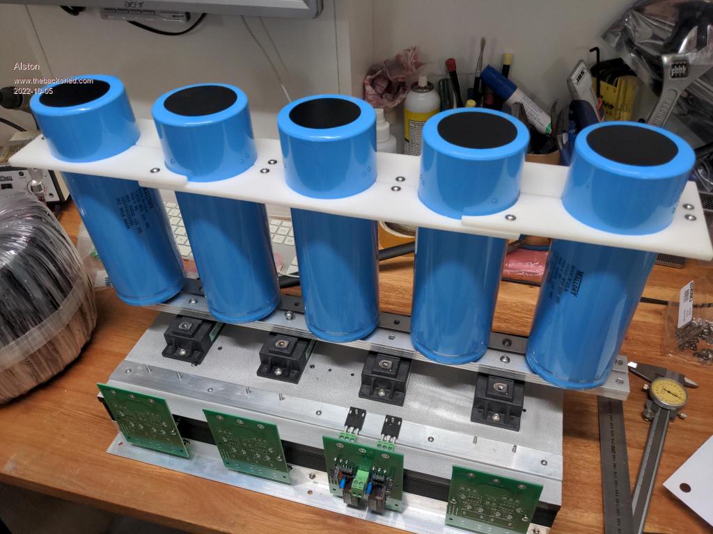
After a lot of work the transformers for my Warpinverter are all finished. After discussion with Warpspeed (Tony) he was confident in using IGBTs at 48v so I decided to do down that route (and Mosfets for the smaller stages). Looking at the curves of the IGBTS they exhibit much smaller voltage drop if you operate them well below their rates current and Tony said his experience with them has shown him they actually perform better than theory would lead to you to believe. Mosfets (if using the HY4008 at least) are cheaper but I managed to find IGBTs at electronic surplus supplier (who seem to sell ex mining equipment stock), so they were only around $45 each. I did find one seller on eBay who said they were genuine but once I received my order I could tell they were either counterfeit or second hand (the terminal look to have been sanded and there was glue ozzing out from the casing) so I sent them back and got my money back, the moral of the story being it takes some careful shopping. I also managed to find some muRata DC-DC converters from a surplus place in the UK and they are happy to operate down to about 30v so that is what I am using for my isolated supplies. I designed some PCBs similar to Warps and my layout will be similar to his. Here is my progress so far: 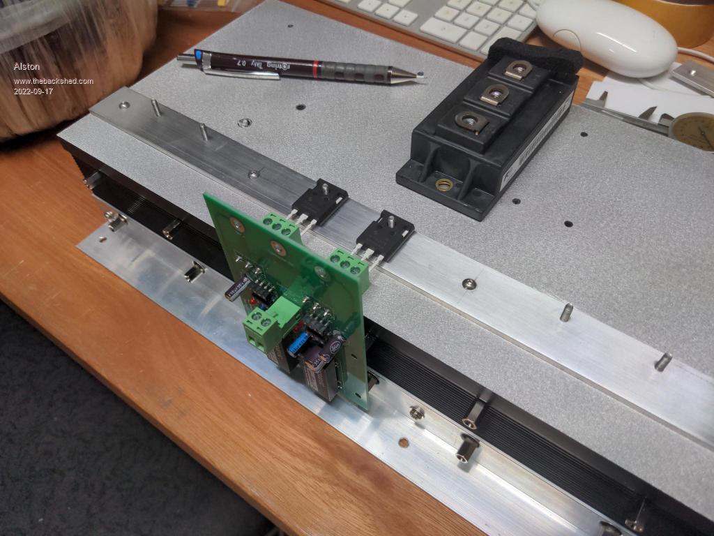 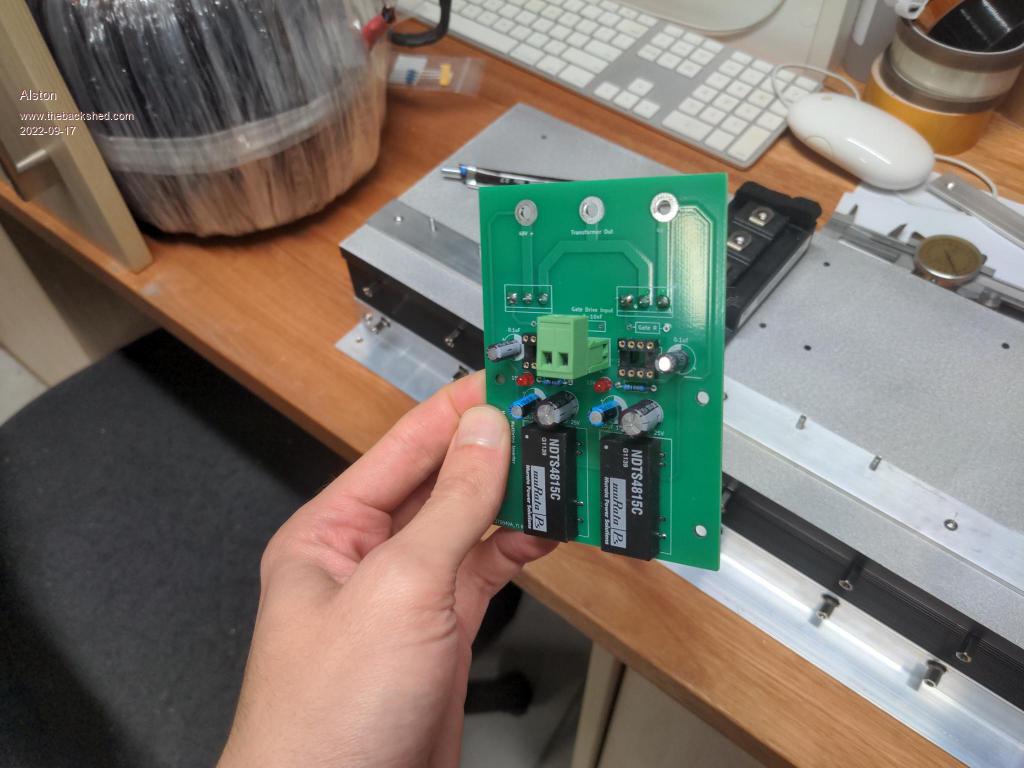 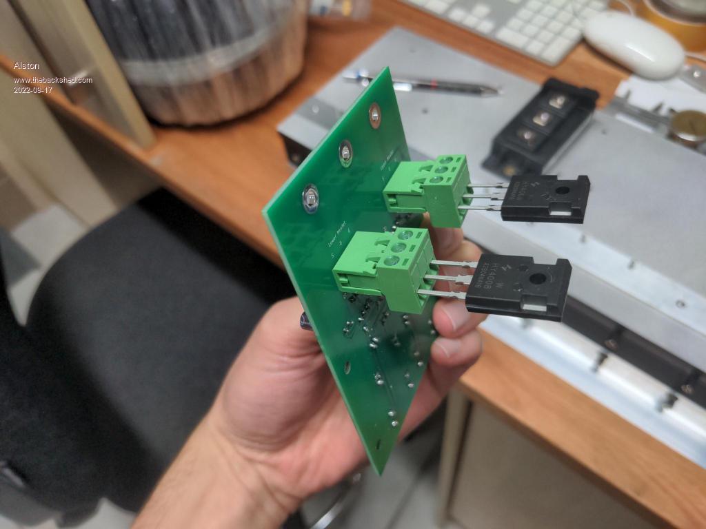 |
||||
| rogerdw Guru Joined: 22/10/2019 Location: AustraliaPosts: 955 |
Wow, very nice looking work there Alston. Very professional. I had wanted to use IGBT modules for the higher power transformers and mosfets for the smaller ones ... but somehow talked myself out of that and stuck with mosfets for all of it. My battery voltage will be 48v and I was concerned about voltage drop across the IGBTs, so that was largely why I changed my mind. I will be interested to see how well yours performs and what sort of idling power. I'm still making progress with mine, but painfully slow. I have built mine as modules, 3 full bridge boards and 2 half bridge boards for the large transformer. I also want to build some spare modules to keep on hand so I can swap any out if they give trouble. Once I fit the mosfets to the modules, I'll put up some photos of my layout. I picked up some 70mm� welding cable on the weekend for the primary of the big transformer ... I had been struggling with the idea of spending $24/mtr x 13 metres for new cable for the big one. On your boards, the green plugs that mount the mosfets ... are they just plugged onto pins on the board ... or how are they connected? Cheers, Roger |
||||
| Pete Locke Senior Member Joined: 26/06/2013 Location: New ZealandPosts: 184 |
I have a great collection of older IGBT's I've ratted from VSD's (VFD's) over the years. As retirement approaches, and the list of projects is being populated, stocking up on these for an inverter as one of the things on the list has been handy. Problem with stocking up on things for projects, is the shed is starting to bulge.... |
||||
| Murphy's friend Guru Joined: 04/10/2019 Location: AustraliaPosts: 678 |
Plug in mosfets? Hmmmm, I sincerely hope you never blow one up. It's very unlikely you'll be able to 'unplug' it after such an event. There was a very good reason why I changed to soldered mosfet legs on removable sub boards. Good luck. |
||||
| Alston Regular Member Joined: 04/04/2021 Location: AustraliaPosts: 63 |
Thanks Roger! I am interested to see how it performs as well, someone had to do an IGBT 48V inverter so I am the guinea pig. I have been interested to see what you have come up with for your boards. I too went through the costings of thick cable and it was hard to stomach, I ended up just doing multiple layers for my primary which was very time consuming but I had enough wire so figured I should use it. I feel like my progress hasn't been that fast as I started in the Christmas break and I am sure I have lots more ahead of me. I used these plugs and sockets- https://www.altronics.com.au/p/p2533-dinkle-3-way-5.08mm-vert-pcb-mount-pluggable-skt/ https://www.altronics.com.au/p/p2513-dinkle-3-way-5.08mm-pluggable-terminal-plug/ Klaus I remember you showing some of the terminals you used but they seemed like this sort https://www.altronics.com.au/p/p2029-dinkle-3-way-3.5mm-pcb-mount-terminal-block/ ? My theory is that the plug itself might be destroyed but not the socket. |
||||
| rogerdw Guru Joined: 22/10/2019 Location: AustraliaPosts: 955 |
Haha, yep. I'm sure they will work fine and I bet I won't be the only one who's interested to see how well they work. If my large transformer section has issues with mosfets, I may have to change to IGBTs myself. I am very happy with the layout of mine ... very easy for access and to work on, though in looking at it the other night I realised I could have made it far more compact if I was really trying to save space. It would be much more difficult to service if I did it that way, so I'm happy to leave it as it is. As soon as I have fitted all the mosfets and the capacitors, I'll post some photos. I did twist up the cable for the smallest two transformers ... and will probably do the same for the third one ... but the big one needs 13 metres and 32 strands of 1.7mm ... so had to bite the bullet and find some suitable cable. You're still way in front of me time wise, I started a couple years ago and then gave up for a while, then started again. I can see the end in sight now so will definitely keep going. Thanks for pointing that out. I'm not sure why I didn't realise they were plugged into a socket ... it may have been the open sided sockets that threw me ... I'm used to the closed ones. Cheers, Roger |
||||
| Murphy's friend Guru Joined: 04/10/2019 Location: AustraliaPosts: 678 |
Paul, it might be wise to check the *current* rating of these plugs/sockets. I my experience, when a 200A mosfet blows then the current causing that is not far of that mark. As I keep saying, mosfets on terminals in inverters, been there, done that, rejected that idea due bad experiences (lots of them  ). ).If you want to make the mosfets easily replaceable without messing with the motherboard, put them on small sub boards of, say, 2-4 mosfets each and connect them to the motherboard via M4 6-8mm long brass spacers. It's not a new idea, the Powerjack inverter boards had it for a long time. BTW, I do have a mosfet on these type terminals in my mosfet tester. There it passes 10A max so no worries. |
||||
| Alston Regular Member Joined: 04/04/2021 Location: AustraliaPosts: 63 |
Klaus they are rated for 18 amps but as they are only used on transformer 3 and 4 they only need to handle 13 amps. Your method is great but I feel this is simpler and will work just as well in my application. |
||||
| Alston Regular Member Joined: 04/04/2021 Location: AustraliaPosts: 63 |
There will be 5 of these capacitors attached to the bus bar (which I have since cut and drilled) and I need to come up with a clamping arrangement which I have some ideas for. I need to have a look for some suitably sized plastic chopping boards as I will make them from that material. I am waiting on some imperial screws to arrive also so I can mount the caps. 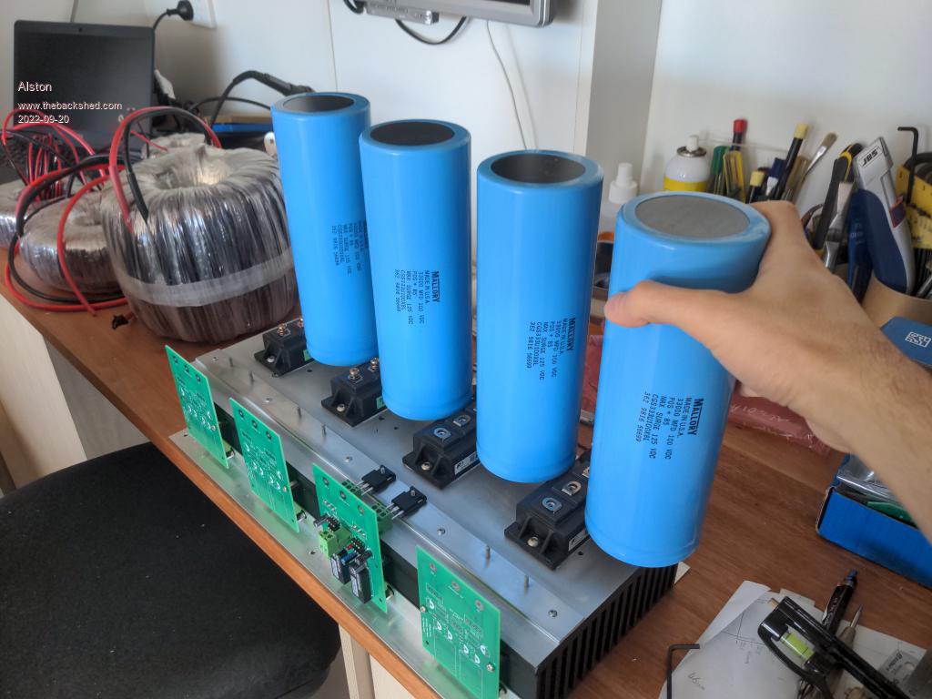 Edited 2022-09-20 23:24 by Alston |
||||
| InPhase Senior Member Joined: 15/12/2020 Location: United StatesPosts: 178 |
What is the ESR of those caps and does it even matter for a warp inverter? I would guess it does. |
||||
| Murphy's friend Guru Joined: 04/10/2019 Location: AustraliaPosts: 678 |
Yes, Ok while the inverter is running. Shall I keep my fingers crossed that you do not have the trouble I had in getting this thing working?  Warpinvertere are at least 4 times more complicated than our other home built inverters. But when it runs its brilliant. Recently mine ran unattended for 6 weeks, powering two fridges and keeping the battery bank full. Back charging from solar GTI is also a lot quieter, no growling even with more than 2KW of solar power flowing into it. Just make very very sure you get the phasing of all these drivers correct and you do not have a faulty driver chip. Those terminals have no chance in a 'bang' event, even at the smallest transformer drivers. I made a test PCB for mosfets & driver chips, I have a spare PCB if you want one. The screws in those big blue capacitors are American 'gauge' thread, I think it was 4G. There was a tap somewhere in my shed to check that. It's not an 'imperial' (British) thread. The screw length depends on your busbar thickness. You also need some support at the bottom (top?) end of that capacitor row. A method to discharge them before removing that busbar assembly is helpful to avoid a nasty 'splat'. |
||||
| Alston Regular Member Joined: 04/04/2021 Location: AustraliaPosts: 63 |
These caps have an ESR of 9mOhms. I would have though the low switching speed that the Warpinverter operates at would mean the ESR of the caps is not that important? Klaus if you could keep your fingers crossed that would be appreciated!  �I think owning a DSO will mean I have a good chance of seeing issues before I do full on load testing. �I think owning a DSO will mean I have a good chance of seeing issues before I do full on load testing. I was wondering if you left it all running while you were away. Did it make you nervous leaving it unattended or you have had it running long enough to feel comfortable? Not sure why I said imperial, they are UNF threads (10-32). Trying to find that on the data sheet wasn't very easy! I went past The Reject Shop today and picked up some chopping boards which I will CNC to make the support structure for the capacitors. I have been thinking about a discharge method, that amount of capacitance makes me nervous.That reminds me when I did my apprenticeship repairing cameras and photographic equipment I would hook up a normal light globe across the capacitors in flash packs and studio flashes as I liked the visual indicator of seeing it discharge, while my boss used a resistor and you would often hear him getting a shock and then swearing. Edited 2022-09-21 22:11 by Alston |
||||
| Murphy's friend Guru Joined: 04/10/2019 Location: AustraliaPosts: 678 |
Nah, no longer nervous about it. I think the gremlins have run out of ideas howe to sabotage this thing (hopefully )My warpverter has now passed more than 2700KWh. The meter counts up in both directions so some of that power came from GTI charging. |
||||
| Alston Regular Member Joined: 04/04/2021 Location: AustraliaPosts: 63 |
 |
||||
| Alston Regular Member Joined: 04/04/2021 Location: AustraliaPosts: 63 |
I have started on the enclosure and have gone down a similar path to Tinker/Murphy's Friend of using the lids from the Aerosharp enclosures to make the top and bottom panels. Here are the photos of the transformer mounting. There are 2 air intakes on the bottom of the unit that will bring air up through the centre of the 2 bigger transformers, as you might be able to see I have fitted fly screen on them. I have epoxied some rubber to the transformer mounts to cushion the wire from the clamps. 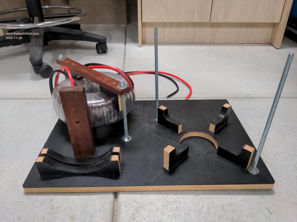 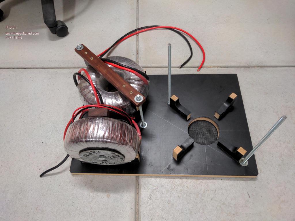 |
||||
| Alston Regular Member Joined: 04/04/2021 Location: AustraliaPosts: 63 |
The enclosure so far. My original plan was to mount the heatsink facing down with the caps standing up but that wouldn't sit into the footprint of the Aerosharp lid so I had to turn it sideways. This gave me the challenge of how to mounts the capacitors. I used threaded rod and aluminum angle to mount to the plastic support to which takes the weight of the caps. 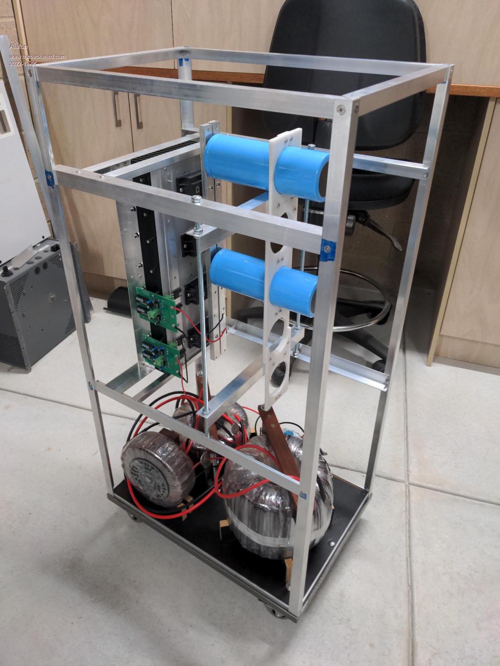 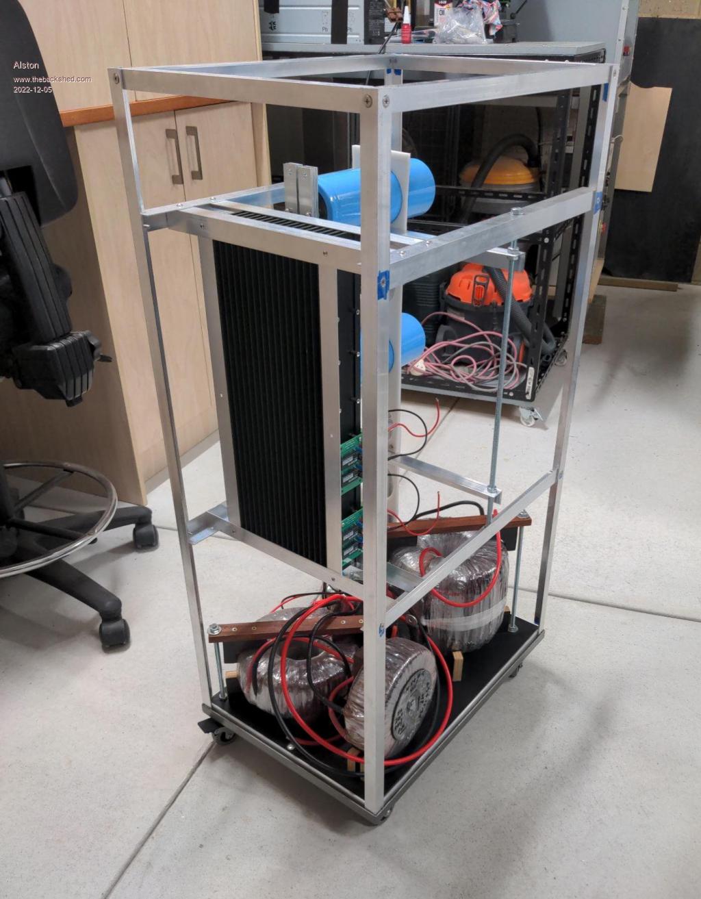 Can anyone point me in the direction of the DC breakers they have? Edited 2022-12-05 23:19 by Alston |
||||
| Solar Mike Guru Joined: 08/02/2015 Location: New ZealandPosts: 1228 |
These DC breakers from TOMZN work well, the store has all manner of DC types. DC Breakers Cheers Mike |
||||
| Murphy's friend Guru Joined: 04/10/2019 Location: AustraliaPosts: 678 |
Those big caps do make a challenging mounting, I like your solution. Did my old eyes spot that you used 3off, 25 x 3mm flat bars in parallel for the cap bus bars? I have used a thin smear of "Alminox" at all contact surfaces of alu busbars to prevent future oxidation and thus loss of contact area. I also used M8 bolts to attach the power cable lugs to these bus bars. Just a minor point but that alu angle at the top of the heat sink (fin side) would allow more convection heat moving up if it was flipped over so its horizontal part faces away from the fins. |
||||
| Alston Regular Member Joined: 04/04/2021 Location: AustraliaPosts: 63 |
Thanks for the link Mike, I will check them out. Is that Aliexpress link a store you have used? Your eyes are close, its 4 of 10x3mm flat bar. I have never heard of Alminox before but have done a search and found it. I will need to order some of that. I had considered the issue of convection but wasn't really sure how much of an issues it will be. I plan on mount 3x 120mm fans to suck air through the heatsink and vent out the side cover. From what you have said about yours heating isn't really an issue. |
||||
| nickskethisniks Guru Joined: 17/10/2017 Location: BelgiumPosts: 481 |
Wow, I like your build, verry clean! |
||||
| Page 1 of 3 |
|||||
| The Back Shed's forum code is written, and hosted, in Australia. | © JAQ Software 2026 |
