|
|
Forum Index : Electronics : Picaxe Pump Controller
| Author | Message | ||||
| Gizmo Admin Group Joined: 05/06/2004 Location: AustraliaPosts: 5181 |
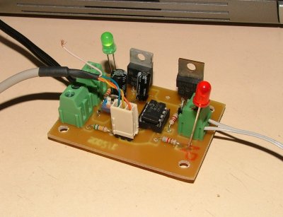
This was a little project to try out the CNC router at circuit board making, and solve a problem with my water pump. I have a 12v water pump to top up my header tank from the main water tank. It uses a float switch in the header tank to drive a relay, and turn on/off the water pump. The pump draws about 10 amps when running. It had a problem, when the tank was almost full, the float switch would bob around on the water and switch the water pump off and on every few seconds. This could last several minutes, and was not good for the pump. So I designed up a simple circuit using a 8pin picaxe. I wrote the program in the little chip to follow these rules. 1. If tank level low, turn on pump for 30 seconds and check level again. Continue to check level every 30 seconds. 2. If tank then becomes full, run pump for a further 60 seconds, then turn off. This gets past the bobbing float period. 3. If the pump has being running for more than 30 minutes, turn pump off, flash the LED once every couple of seconds. This means it has taken too long to top up the tank, so there must be something wrong, ie Main tank empty, leak in the line, float switch stuck. You need to turn the controller off and on to get back to normal operation. 4. If pump is on and battery voltage drops below 11 volts, turn off pump, flash led twice every couple of seconds, and wait for 20 minutes. After 20 minutes, check battery voltage again, if recovered enough, turn pump back on. This saves the battery, gives it a chance to recharge before starting pump again. The completed controller circuit board.
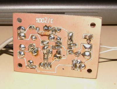
And this is the back, you can see the lines engraved by the router to make up the circuit paths.
I'll write up an article on the weekend, and include the circuit diagram and program code. Glenn The best time to plant a tree was twenty years ago, the second best time is right now. JAQ |
||||
whirlybird Newbie Joined: 08/02/2006 Location: Posts: 27 |
Hi Glen. A few questions. Dont seem to be able to find the rest of this article or is it not done yet ? Would you be prepared to rout out a couple of those boards for me I will of course pay you for them. Looking forward to examining the code as well. Regards. Whirlybird. I am because I am.I am not always right but often I am. |
||||
| Gizmo Admin Group Joined: 05/06/2004 Location: AustraliaPosts: 5181 |
Hey Whirlybird. Rest of the article here. http://www.thebackshed.com/Windmill/PumpControler.asp Sorry but wouldn't be able to supply the circuit boards. Too little time and too much work. But its a simple circuit, so you could use veroboard. Glenn The best time to plant a tree was twenty years ago, the second best time is right now. JAQ |
||||
| The Back Shed's forum code is written, and hosted, in Australia. | © JAQ Software 2026 |