
|
|
Forum Index : Electronics : Inverter went up in Smoke
| Page 1 of 2 |
|||||
| Author | Message | ||||
| andymc70 Regular Member Joined: 30/06/2019 Location: AustraliaPosts: 43 |
Hello All Well, Murphy struck on the weekend, went away for the weekend, had everything off the inverter except a laptop, and come home to it off and black soot around the inverter. I saw all the soot-covered webs up behind the inverter so, it must have caught on fire. I opened it up and found the following pictures: 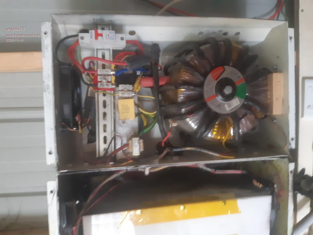 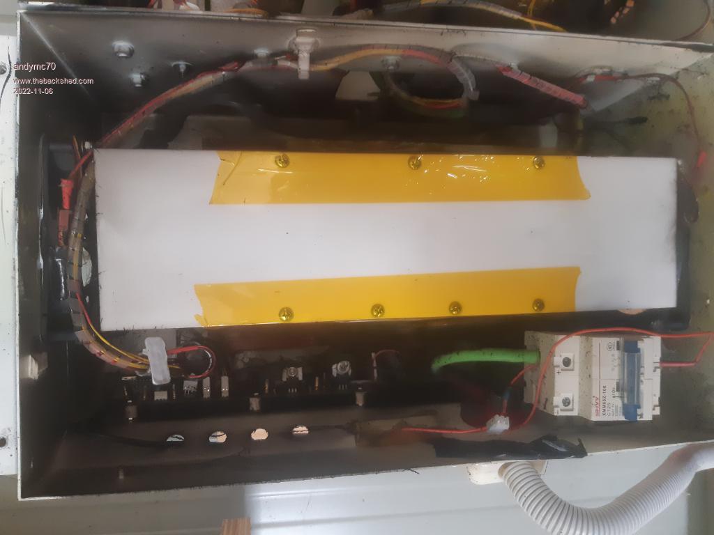 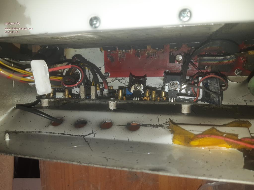 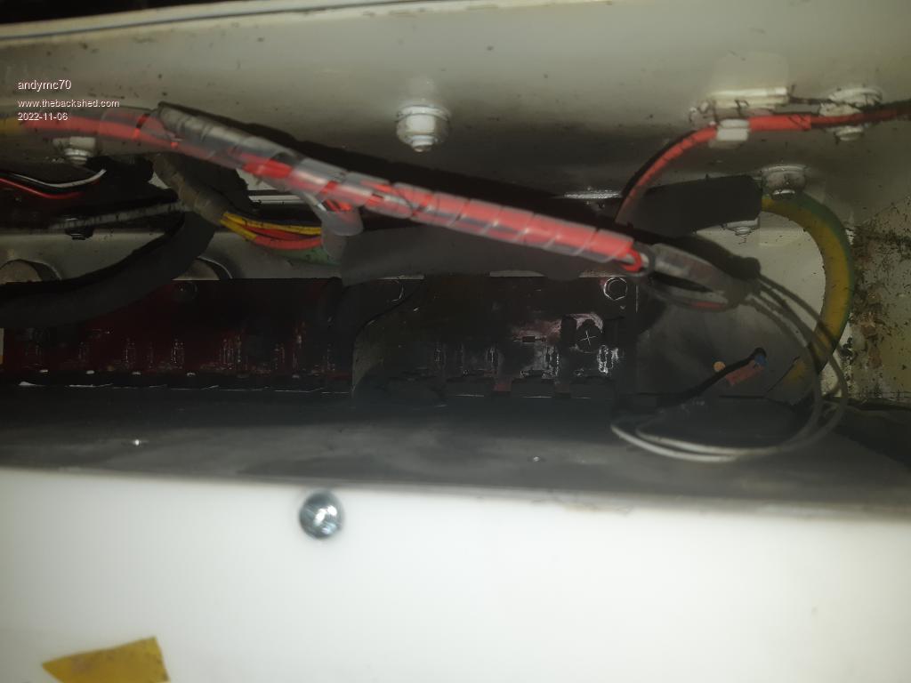 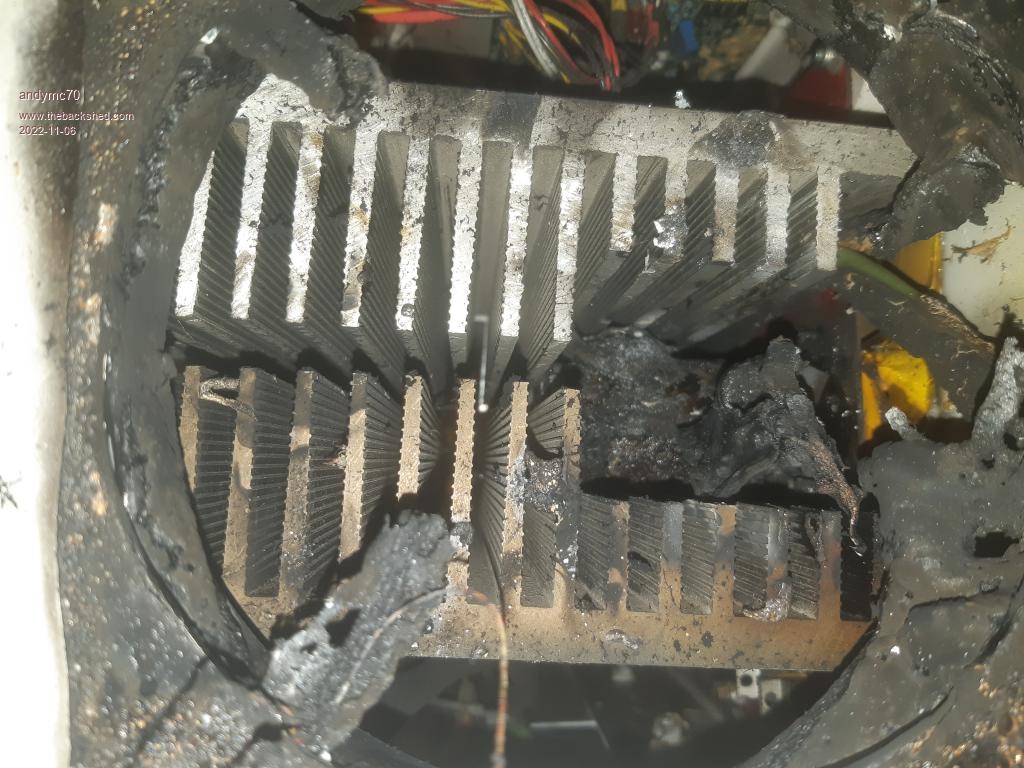 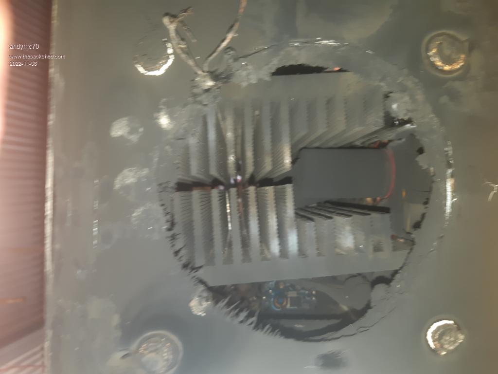 The torrid side is fine. I have stripped it down now, the brain board looks out, it needs cleaning. If anyone has the best way to clean these boards. I would love the advice. 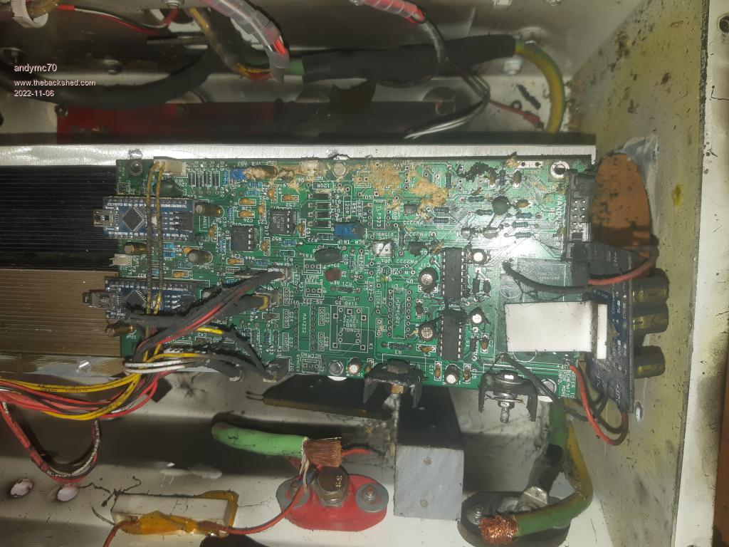 Here is the main board, not sure if it can be saved, I will try to clean it up and see which components need to change or if am I better off just starting a new one. 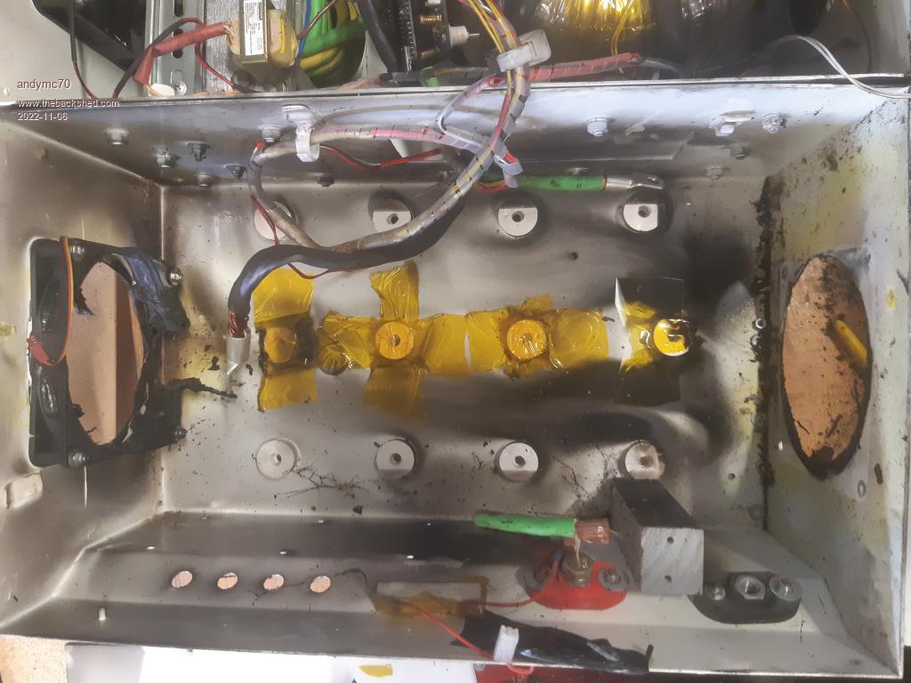 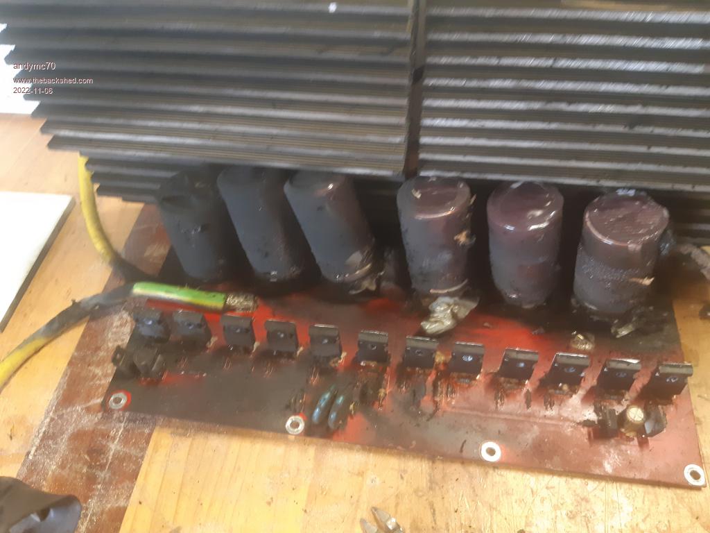 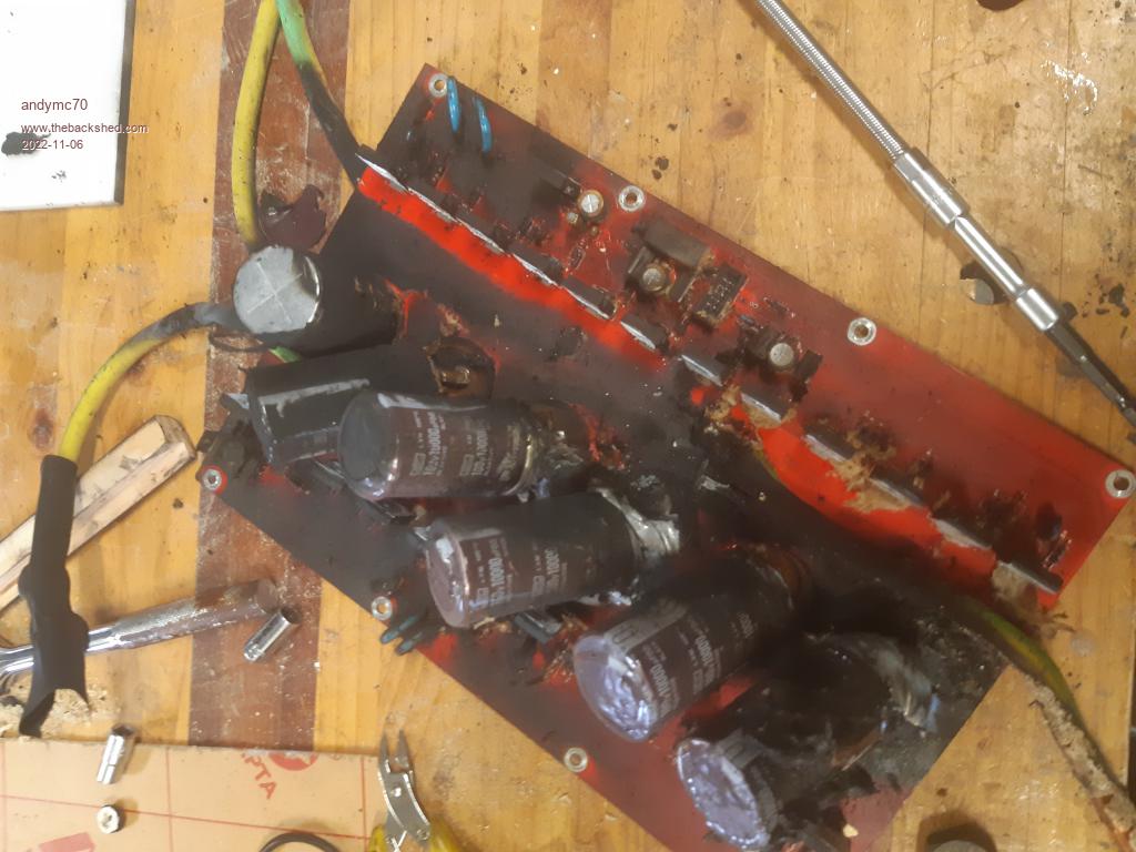 I am can not seem to put my finger on why it happened. If anyone has some ideas please let me know. I know I will be changing the fan covers as I think they are the main cause of all the soot, they were ABS 3d printed screens. It seems the fire started in the bottom LH corner of the main board. Here is what is left of the fans. 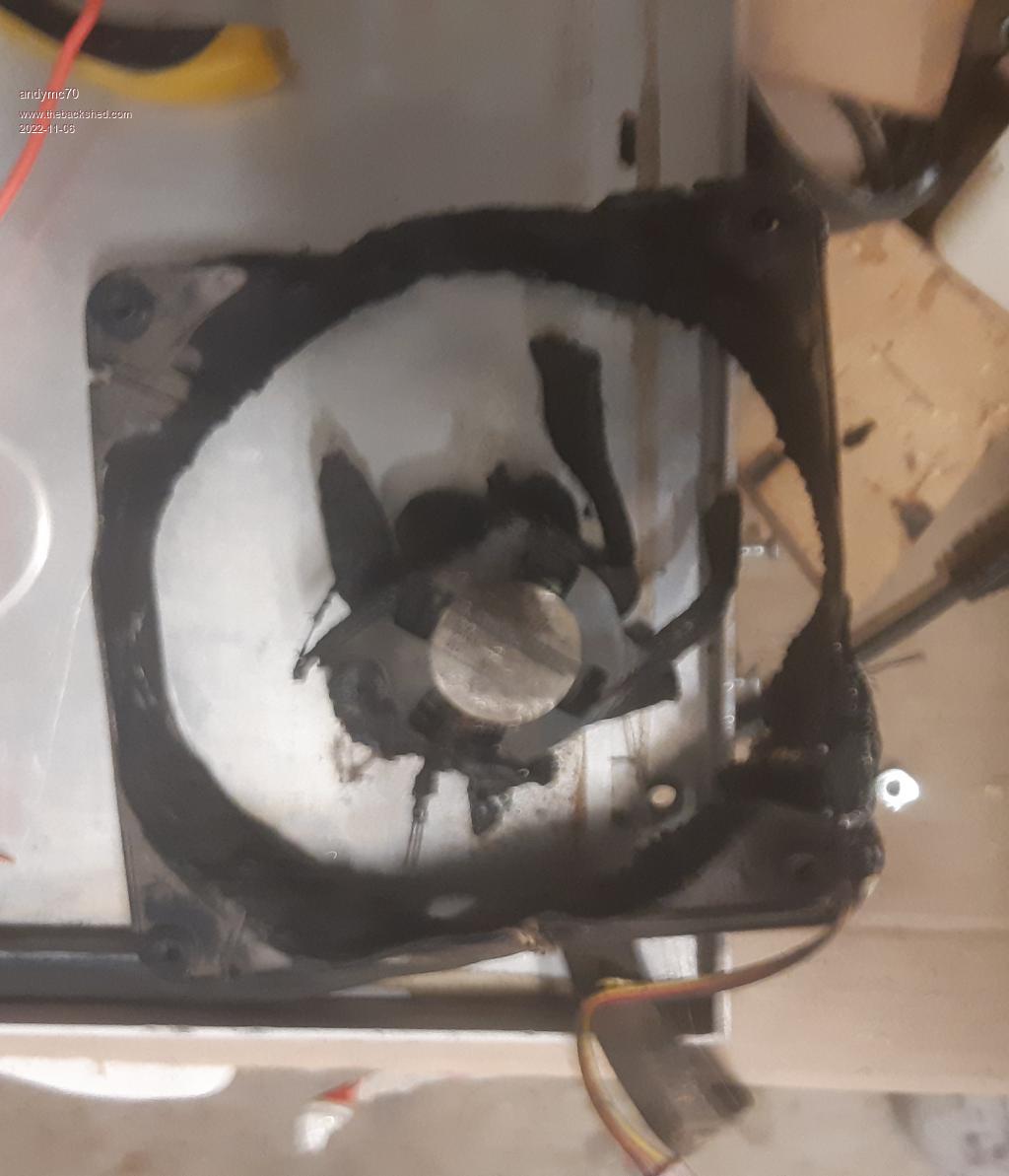 Also, I use a 14S powerwall, the last cell fuses have all blown. Any help would be greatly appreciated, I have a nervous wife now and I need to reassure her it won't happen again or why it happen. Thanks Andy |
||||
Revlac Guru Joined: 31/12/2016 Location: AustraliaPosts: 1282 |
Thats not good, not sure what happened either, the mosfets look OK or at least not blown to bits. I wonder if the capacitors might have instigated some of it. Cheers Aaron Off The Grid |
||||
| Murphy's friend Guru Joined: 04/10/2019 Location: AustraliaPosts: 678 |
Wow, that is the worst blow up I have seen posted in the many years I have been here. Had quite a few 'mishaps' with my early inverters but nothing like this, even the big cables seem to have disconnected themselves from the terminals. I am wondering if that what looks like an angle grinder disk had ground thru the primary insulation when it got warm  ? ? I agree with Aaron that the capacitors might well have started the fireworks. Always thought that between the heatsinks is the worst place one can put them, none of the 6 inverters I built have them there. Unfortunately, this looks like a total loss, by the look of it there are not many salvageable parts left in that recycled Aerosharp housing. You have been unlucky, earlier this year I went for a 6 week long caravan holiday with two home built inverters left unattended, running the house, and had no problem whatsoever. |
||||
| noneyabussiness Guru Joined: 31/07/2017 Location: AustraliaPosts: 527 |
wow, good job... glad it wasn't worse... to clean the pcb use some isopropyl alcohol, I'm sure madness has a better mix with acetone but I've found just iso is great... you may have had a creepy crawler or moisture short something out, if you grab yourself a can of This stuff and spray everything when you've replaced and/or repaired the boards you won't have that issue anymore... mine has been outdoors ( under cover) for years with no issues... hope this helps... I think it works !! |
||||
| Godoh Guru Joined: 26/09/2020 Location: AustraliaPosts: 675 |
Wow, glad to hear that the fire did not spread. As noneya says Isopropyl alcohol works great, also hot soapy water does a reasonable job too. Just wash the boards well then rinse in hot clean water. If it were just a capacitor failure then the boards may be ok, but the fact that the fan melted as well means there was a lot of flames. Not sure why your circuit breaker did not trip and stop the fire though. Good luck fixing it. Pete |
||||
| wiseguy Guru Joined: 21/06/2018 Location: AustraliaPosts: 1297 |
The control circuit board does not look too bad. When I have had to clean burnt messes from a PCB I have found that either pink or clear PVC gluing solvent works wonders when Metho/Isopropyl wont quite cut it, but I agree first wash with warm soapy water and dry with compressed air/warm oven first. I usually just dip a cotton bud into the solvent and vigourusly wipe the affected areas. I also have green fingernail varnish to reseal any exposed fibreglass areas (under the charring) and it looks almost as good as new. (Try it on some badly burnt areas of the power PCB) I also agree with earlier comments that it appears that the capacitors failed. They look a lot like Nichicon or United Chemicon but I could not make out the brand from the pictures. If they were bought from Aliexpress they could even be poor knockoffs. Either way if the inverter has been running for quite a while without issues then why did it fail now ? Capacitor failures are usually bought on by high ripple, high voltage or and excess temperature, I think the high voltage can be discounted but the ripple and temperature are more likely. What choke were you using ? Also is it possible the fan or fans failed (or their power supply?) That could elevate temperature causing choke and capacitor degradation. Maybe the lower fan failed and ignited causing the fire ? Never scrimp on fans, I always use quality (Sunon does it for me) and magnetic bearings or at least ball bearings when realiability is paramount. I am also curious that the circuit breaker did not trip earlier (I assume it was tripped when you first investigated ?) Any way commiserations and good luck fixing it. Out of curiosity what power PCB was being used in your inverter? I am not familiar enough with Madness/Chinese/other PCBs. Edited 2022-11-07 10:52 by wiseguy If at first you dont succeed, I suggest you avoid sky diving.... Cheers Mike |
||||
| Revlac Guru Joined: 31/12/2016 Location: AustraliaPosts: 1282 |
Unfortunately a slow burn due heat from a short circuit of 15-30Amps will not flip the circuit breaker, what to do about this? If left unattended for some time and not expecting to run anything with a high current start, you could wire in a 10amp circuit breaker or what size is required, it may have stopped some of the damage but its a nuisance to do it like that. I think most of us have high amperage breakers or fuses, so not immune to this situation.....any ideas? Cheers Aaron Off The Grid |
||||
| wiseguy Guru Joined: 21/06/2018 Location: AustraliaPosts: 1297 |
Aaron, yes high currents below the breaker trip current can cause a lot of grief, its a question of whether the grief isolates itself by vaporising enough "stuff" to become open circuit or enough current flows to finally trip the breaker. Maybe a breaker like this �could be force tripped with a bit of circuitry coupled to a thermistor say set to 80 degrees or/and a smoke detector sensor too? More info here part numbers ending with RT = remote trip. It has just been quite graphically demonstrated that the possibility of a house/workshop fire is very real if not enough caution/mitigation is used. The remote tripping circuit breaker is looking like a good option to me. Edited 2022-11-07 13:14 by wiseguy If at first you dont succeed, I suggest you avoid sky diving.... Cheers Mike |
||||
| andymc70 Regular Member Joined: 30/06/2019 Location: AustraliaPosts: 43 |
Just wondering if you could link your builds, be interested to see where you put your caps. The capacitors were the cheap aliexpress Cap's, I wonder how many of these are being used in other inverters, I got the link from this site. Here are the ones that I used. Capicators Bought I have just read POIDA post about cheap caps. Cheap Capicators could be costly I am wondering if it was the fan, I haven't been happy with them. These are the fans I used. Fan Used I defiantly scrimp on them, I will be looking for better quality ones before summer gets here. I was thinking of putting an inline fan on to push more air. People thoughts? Now the inverter has a 100amp CB, I am changing it to an 80-amp one. I just want to clarify something, I might be wrong with my electrical understanding here. My powerwall is a 14S108P DIY powerwall. Each cell is a pair of 18650 batteries and they are fused with a 0.5amp fuse, so that would be like a 54amp fused per column. So my closest column of cells (No 14) to the inverter all fuses blew. So I am assuming there was a short that was above 3kw as the battery was at 50V when I got home. So the battery CB sort of worked. Just a side note and hopefully some education for me, I am in the process of changing all my fuses to a 2amp, so my powerwall therefore each series, and the battery would have a 108 amp fuse overall, I think this makes it 1C safe. Is my understanding correct? It is madness board. Edited 2022-11-07 17:15 by andymc70 |
||||
| Solar Mike Guru Joined: 08/02/2015 Location: New ZealandPosts: 1228 |
About the only electro's that I would trust for use in inverters from AliExpress suppliers are These Link, this brand seems ok at high frequency and current, none have blown up yet. Unfortunately most online suppliers on that platform are ripoff of fakes and cannot be trusted for semi-critical operations like inverters or charge controllers. Stick with the named brands from RS, Element14 etc, then you know what you are getting as they have a spec sheet, assuming they have them in stock and not on 12 month back order. Cheers Mike |
||||
| poida Guru Joined: 02/02/2017 Location: AustraliaPosts: 1480 |
The Aliexpress 100V 10,000uF caps I use have been not very good when used at 95V. It blew very soon after I put it into use. Now I see some question about what the DC supply was, that is, what voltage it was before or during the incident. I think that will need some investigation. The inverters I have use these caps and the DC voltage is from a Lead Acid battery of 48V so it might get up to 55V or 56V sometimes. No higher. When the inverter blows when running with low power loads it suggests overvoltage on the caps or too low inductance in the choke. When I was using the Aliexpress powerboards that used gate drive ICs conencted direct to the FETs I suspected over/under voltage on their outputs that gradually led to failure of the IC outputs. This also meant a blowup. I think we can expect decent Gate drive for the low and high side FETS thanks to the robust totem-pole drive. Also the cause could be bad Gate drive timing. Maybe the nanoverter died or had brownouts.. All my blowups were where the energy was concentrated in one or both sides of a half bridge. The FETS blow off package leads, open up the packages and that sort of thing. Usually one half of the inverter is blown and 1/2 half if not too bad. The caps always looked like they were OK and I put them into service in the new build. I wonder if the FETs will test as OK? Maybe 1/2 of it. But no point of using anything from the blowup, I would expect all FETs to be suspect and all totem-pole drive parts to be stuffed. Anyway, I have spare inverter power boards and spare picoverter control boards for you. My inverter has a 100A fuse on the DC supply so it will blow when a good amount more than 100A is drawn. Also there is a 63 DC contact breaker. At least 2 blowups have had the 63 A CB open after the bad things happen so I think they do work, but no idea what current and for what period of time will cause them to open. I use them as isolators more than protection. wronger than a phone book full of wrong phone numbers |
||||
| pd-- Senior Member Joined: 11/12/2020 Location: AustraliaPosts: 122 |
C curve or K curve seem to be the most common DC CB's that are being soled  It looks like a cap has failed then a spark has ignited the electrolyte. |
||||
renewableMark Guru Joined: 09/12/2017 Location: AustraliaPosts: 1679 |
I used ebay caps on mine and even after each blow up I re used those caps. Still work just fine. Did something fall in and create a short? Caps normally pop at the top when they fail don't they? Yours look like they have been blown off the board from the bottom. How does the battery test after fixing the fuses? Could any of the cabling you used have soft insulation that could have failed when it got hot? Jaycar DC cable is like this. A loose or rusted connection can make joins incredibly hot with just a few amps. I had a power supply that wasn't acting as it should and I checked the croc clip, it was burning hot, inside the connection was only crimped and it was rusted, creating a sh*t connection with enormous resistance. Cheers Caveman Mark Off grid eastern Melb |
||||
| renewableMark Guru Joined: 09/12/2017 Location: AustraliaPosts: 1679 |
I just noticed one of your caps is smaller. It might be ok to mix different spec caps, but I would be inclined to have them all the same. 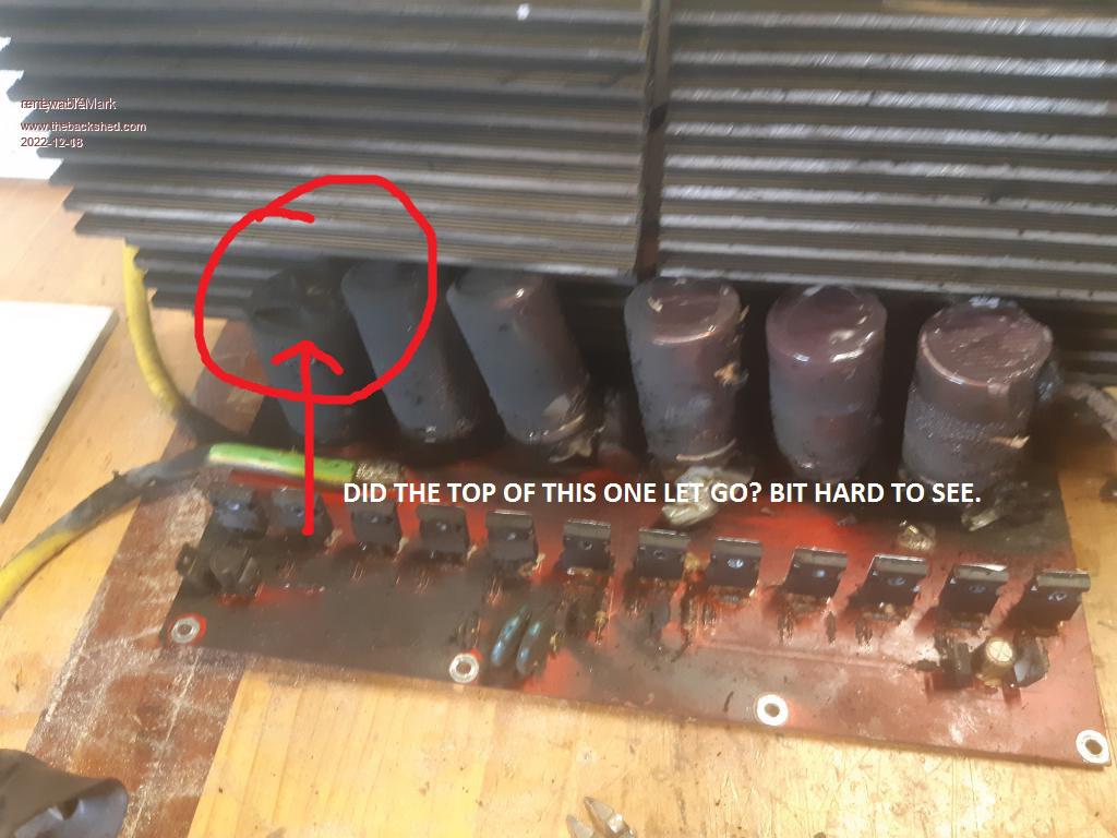 Cheers Caveman Mark Off grid eastern Melb |
||||
| noneyabussiness Guru Joined: 31/07/2017 Location: AustraliaPosts: 527 |
I use 2 63a breakers ( on dc, 48v) from Bunnings, 10KA models, they break at 9.5kw and will do 8-8.5 kw for around an hour before tripping from temperature, which is about max I'm comfortable with on my inverter ... in several years Ive had to replace them once, They have tripped several times over those years from overload ( hence why I know how much they can handle ;))... I remember Oztules doing very similar and having no issues ether... I do have 125a dc breakers on each of my battery banks as well ... Ive found the same poida, usually the " 20khz " side of the EG8010 H bridge that goes... I think it works !! |
||||
| andymc70 Regular Member Joined: 30/06/2019 Location: AustraliaPosts: 43 |
Hello All Merry Xmas and happy new year. Well, I got an early Xmas present this year, I got the inverter back up and working. Thanks to Poida for testing the boards and finding nothing too seriously wrong with them. Here are the boards after I cleaned them, thanks for the suggestions, I used nail polish to cover the exposed copper. 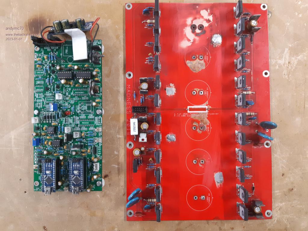 I had to reuse the boards whilst waiting for components to arrive. I will replace the brain board over with the pico when the parts come. Then I will have spare boards if anything happens again. I put new caps from RS components and new fans as well. Now what happened, I think I have sorted it out (with Poida help), just unsure which order it happen in. So I had the following faults, (1) 1 battery cell all shorted out. (14S Li-Ion Powerwall) (2) the transformer to the laptop connected doesn't work anymore (3) a POWER Mosfet shorted out in the MPPT controller, so the whole solar array was on the battery side with no battery connected, So I know that from the above faults, this put close to 100v on the inverter which destroyed the caps and started the fire. So how to ensure this doesn't happen again? (1) Increase the individual cell fuses in the power wall, I realise they are only at 0.25amp per cell, will increase this to 1.5amp per cell, which therefore will increase the individual pack to be above 100 amps capability each pack is 72 cells, I have 3 packs in parallel, so 300 amp, with my whole battery having a 200amp CB, I hope this goes first before an individual cell. (2) Replaced the transformer and if this course a short and the battery went before the 25A AC CB in the Inverter, then (3) will solve this and make sure the AC CB goes first. (3) With the Mppt, I going to put a crowbar circuit on the battery side with a 75v Zener diode to trip the 50amp CB'S connecting the Solar and battery to the MPPT. I hope this idea will work. (Also not sure if this was caused by the cell going or it's caused the cell to go.) (4) Better real-time monitoring. Defiantly will need help with this. Looking at changing my LCD Nano's over to the nodemcu device, which hopefully will allow me to put the data onto the internet. (I am still not 100% sure if I can do this) Sorry not sure if I have the skill set to do it your way Poida, my coding is very limited and still trying to understand and learn what is happening in the mppt and pico codes). Thanks for all the support and help, hopefully no more issues. Andy |
||||
| andymc70 Regular Member Joined: 30/06/2019 Location: AustraliaPosts: 43 |
The caps were all blown on the bottom, not sure which way they normally go, I have had smaller ones go both top and bottom. Yeah battery is working well, the individual fuses are designed for the individual cell short, but when I first built the powerwall it wasn't meant to be this large and run the house, so it's just a slow process of learning and replacing the fuses. I have overcompensated for the size of the wiring, and one thing I learned early is how hot things get from the current. I can't believe how hot my MPPT is getting, I think of putting a bigger heatsink onto it. No all caps were the same, that one didn't blow, it was closet to the battery. Thanks Andy |
||||
| noneyabussiness Guru Joined: 31/07/2017 Location: AustraliaPosts: 527 |
try 68 Volt TVS diodes, higher current capability and will sometimes even survive a over voltage event ( 1000's of amps over a short time, Nano seconds) tougher than " standard " zenner diodes... will definitely trip a breaker if you put a few in series with battery input/output of MPPT while protecting downstream of them... AU $1.50 | 20Pcs/Lot Non-Polar P6KE TVS Diode DO-15 P6KE6.8CA~P6KE440CA P6KE12CA P6KE33CA 47CA 56CA 250CA Transient Voltage Suppressor https://a.aliexpress.com/_mO5jdng your looking at the " P6KE68CA " these are awsome little units, with built in relay control in a overvoltage / overcurrent evet ... AU $44.18 18%OFF | 100V 100A 200A 300A DC Voltage Meters Ammeter Power Meter Power Sheet Coulometer Electric Vehicle Battery Capacity Monitoring https://a.aliexpress.com/_mtt140I I did a write up on replacing the nrf24l01 in them, with the booster attached for extra long range of the wireless function on this forum somewhere ( do a search, Ill find it if you interested) I think it works !! |
||||
| Page 1 of 2 |
|||||
| The Back Shed's forum code is written, and hosted, in Australia. | © JAQ Software 2026 |
