Notice. New forum software under development. It's going to miss a few functions and look a bit ugly for a while, but I'm working on it full time now as the old forum was too unstable. Couple days, all good. If you notice any issues, please contact me.
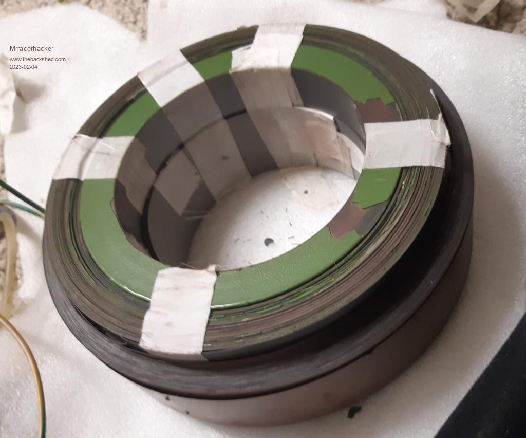
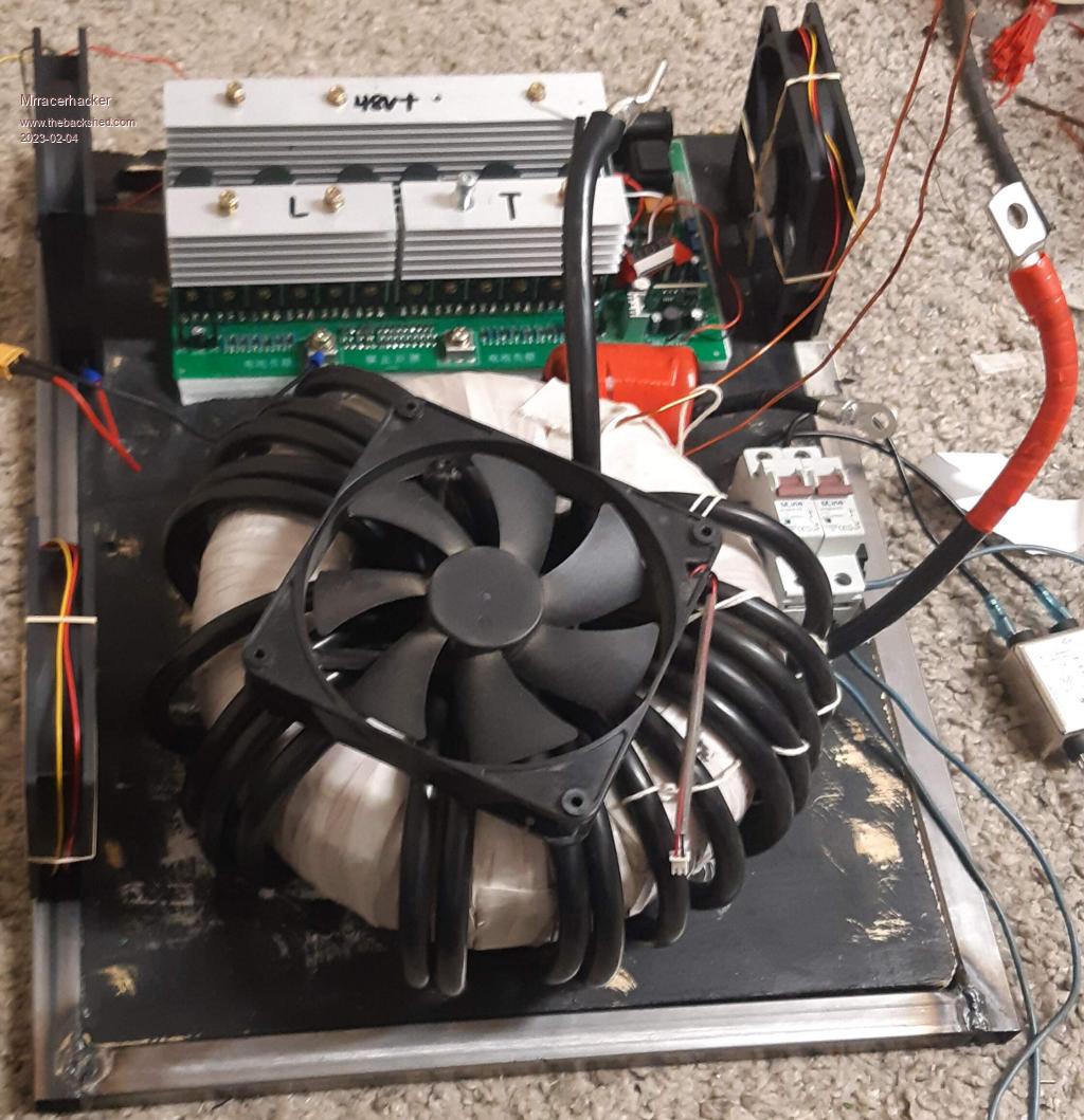
Had a long time project, taken a few months to get where i am think started a bit after summer with reading, but do got the time so thought why not, at the moment its not more than a ups setup, but thinking adding some wind/solar in later time had 3 cores of various sizes, unwound them and got wrapped them together, not the best job, cast in a bit of epoxy then wrapped with mylar wrapping
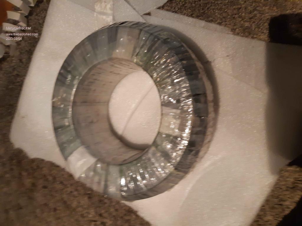
then went for a few layers of "glass fiber transformer tape" and some more reinforcements on the egdes, would prob recommend just grinding a chamfer, learned from earlier mistake, better if you got "smaller" cores its good go for as big as hole size as you can id say, makes it easier, this is 130mm ID 230mm OD and 90mm H, Core is around 1,4V per turn which gives 169 for 240.
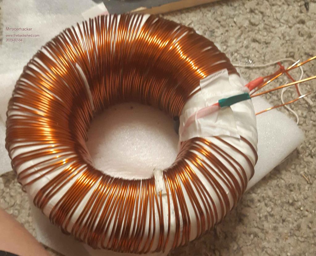
onle last layer unsure if i got another pic should have somewhere of the last layer, but alas, it is 1.8mmX3 which should be good enough for 25a not that i need that much. primary cable is 50mm2
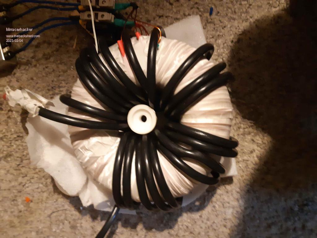
this is ca the layout, working on the enclosure now. got the plates cut just need to weld them up but not pictured yet
got alot of 48v batteries from ebikes which i want to use, but thinking lifepo4 in the future safer that. done some testing on the bench with other toriods and such, tho know i should make a choke, got one but thats just one bought from china
need to find the right inductance to reduce the humming, as it do hum a bit, but not too bad, but know it can get better, do have a few caps i can change out Edited 2023-02-04 04:13 by Mrracerhacker
tinyt Guru Joined: 12/11/2017 Location: United StatesPosts: 561
Posted: 09:46pm 03 Feb 2023
Copy link to clipboard
Print this post
I have a similar setup. The toroid is a modified 5kva.
Looks like we have the same inverter power board from aliexpress which uses a substitue EGS002. I have also modified it slightly, also I am now using EGS002.
The 2 ohms in the picture is temporary which I added at first power on just in case there are shorts, it is now removed. I have also changed the 5 uF capacitor to lower idle power (very slightly). This is still a work in progress. Edited 2023-02-04 07:50 by tinyt
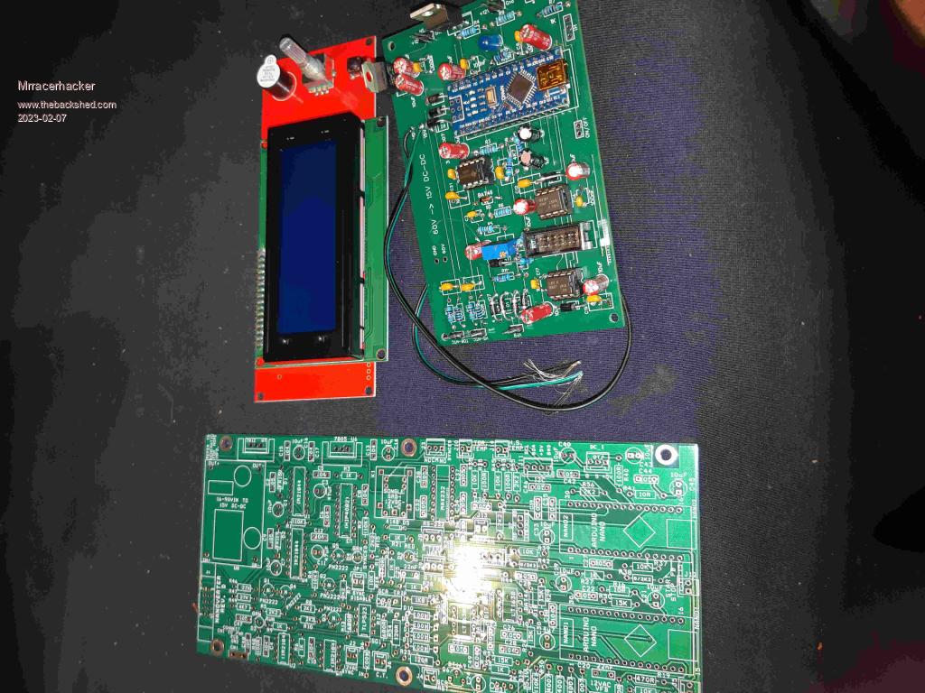
Nice build, yeah do look like the same board, got an odd driver board, driven by an ati chip, thinking adding an nano/picoverter for controlling it later, only got up to 3 uf as thats what i had on hand but do know it needs some tuning, goes around 36W on idle on my inverter
got my boards yesterday, soldered up the picoverter, nanoverter for later usage, no magic smoke when ran at 15v which is good
poida Guru Joined: 02/02/2017 Location: AustraliaPosts: 1480
Posted: 07:34am 07 Feb 2023
Copy link to clipboard
Print this post
good to see.
If you have a CRO or DSO, have a look on a few pins on the IR2148 when you press the "run" button. Check Pin 1 for PWM output from the nano, should be 5V pulses Check pin 4 for the low side drive, should be the inverse of pin 1 and at 15V too.
Notice that the two gate drive chips are not aligned the same way. One is up and one is down.
Vfb will be a bit tricky to set. I always use a bench supply so I can take it up from about 30V seeing the output AC voltage. The trimpot needs to be set to your desired output voltage and sometimes the trimpot is set already to make the inverter output way too much.wronger than a phone book full of wrong phone numbers
Got a Cro will take a look. gate chips are okay, this ver got them inverted, can take a pic of the board when im home, but pretty sure as inverted VSS points Edited 2023-02-08 04:55 by Mrracerhacker
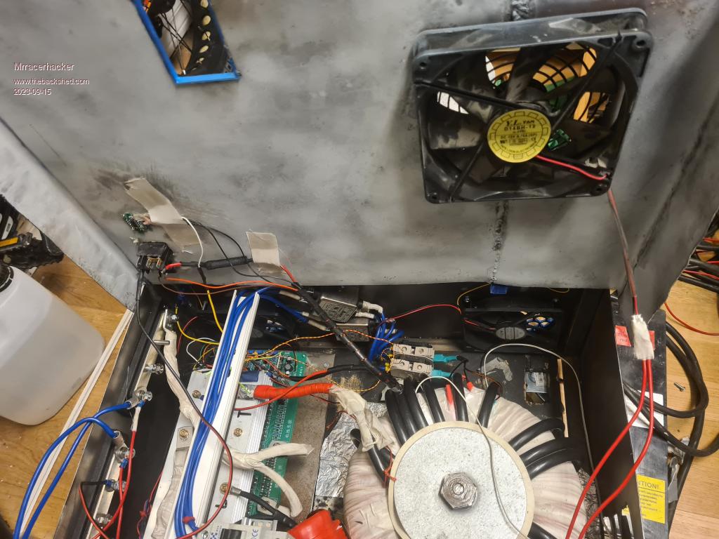
Bit late, forgot to upload some pics, been running here and there for the last year, tho no real high load, idle is at 36w if i recall right, should rewind the choke for another one one day, should should tidy the wires a bit better but goes so far, next for this one is i think getting some transformer varnish under vacuum and coating the transformer.
Welded steel box out of scrap sheet
Revlac Guru Joined: 31/12/2016 Location: AustraliaPosts: 1282
Posted: 12:09am 16 Sep 2023
Copy link to clipboard
Print this post
Good, do you have the LCD working?Cheers Aaron Off The Grid
only have another screen for tempratures and fan control, dident go for the inverter driver board and Madness one, stil on the bench that one, should finish that one day this, still running chinese inverterboard for my usage case


.jpg)


 Good, do you have the LCD working?