Notice. New forum software under development. It's going to miss a few functions and look a bit ugly for a while, but I'm working on it full time now as the old forum was too unstable. Couple days, all good. If you notice any issues, please contact me.
rustyrotors Newbie Joined: 07/01/2023 Location: United StatesPosts: 32
Posted: 07:10pm 19 Feb 2023
Copy link to clipboard
Print this post
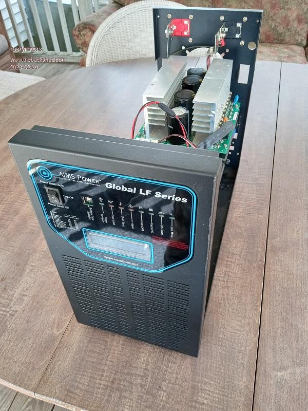
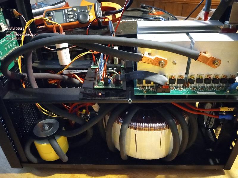
so i bought this aims 24v 6kw inverter/charger about 10yrs ago.. i quickly discovered it pulled 180W at idle, which drained my battery dead in a day, very disappointing. it was also stuck at 50Hz if no grid power was connected, and i need 60Hz offgrid here in USA. i contacted aims to find out how to configuire for 60Hz permanently, but they said they could not help, they no longer have the schematics for the older units. so its basically unusable for my 2kw full offgrid solar setup. it also had the breakers wired incorrectly, would have been a fire hazard so it sat unused until recently, i discovered this forum, been reading how to build a diy inverter. my plan is to retrofit it with an EGS002 board for better efficiency, and ill have a nice backup inverter
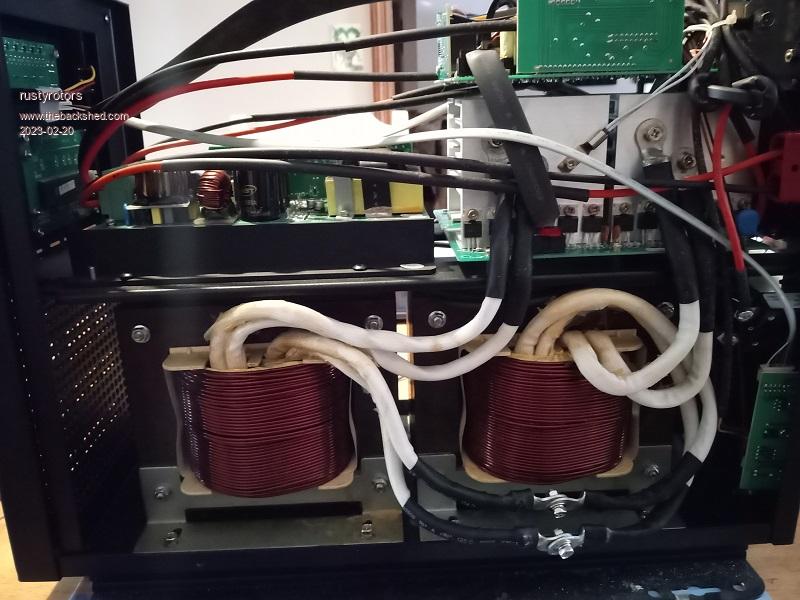
here it is with cover pulled. i measured the draw on the trans individually at 115V.. 55W each no bueno. the fans drew 35W and ran constant. i yanked all the guts out, but kept the mosfet board.
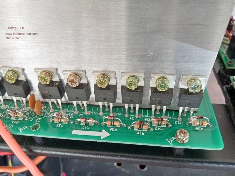
The mosfet board had 24 IRFB3206 fets, each with 47 ohm gate resistor, no reverse diodes. To work better with the EGS002, I swapped the gate resistors for 30 ohm and added 1N4148 reverse diodes. i figure that should keep current draw from the IR2110s under 6*12V/30ohm = 2.4A
rustyrotors Newbie Joined: 07/01/2023 Location: United StatesPosts: 32
Posted: 07:14pm 19 Feb 2023
Copy link to clipboard
Print this post
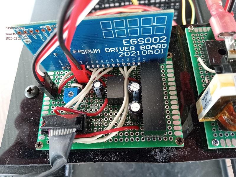
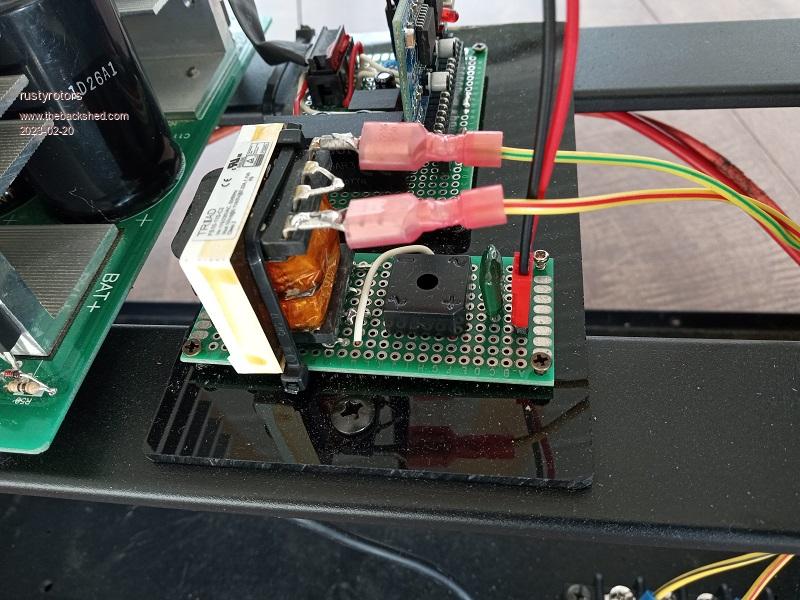
Adapting EGS002 board first had to fix the snap crackle pop bug on the EGS002.. i removed U4 and shorted C19 and C24 to disable overcurrent protection. i made this super minimal board for adapting the EGS002 to the aims mosfet board.. it has 5V and 12V supplies and a pot for adjusting AC output voltage
24V to 12V supply, 3A https://www.digikey.com/en/products/detail/mornsun-america-llc/K7812-3AR3/13168201 24V to 5V supply, 1A https://www.digikey.com/en/products/detail/cui-inc/P78E05-1000/9649654
it gets 24v power from the aims mosfet board idc connector, still need to should add a fuse inline somewhere, for got to put that on the board. Voltage feedback uses a 230V to 5V trans and a bridge rectifier i had laying around
rustyrotors Newbie Joined: 07/01/2023 Location: United StatesPosts: 32
Posted: 07:22pm 19 Feb 2023
Copy link to clipboard
Print this post
Toroid transformer i came across these on ebay..
search for "5000 step up down transformer." they have big toroids in them with two 115V windings in series and a nice case for $100, convenient for USA split phase. all you have to do is add a primary winding for inverter use https://www.ebay.com/itm/124889104671
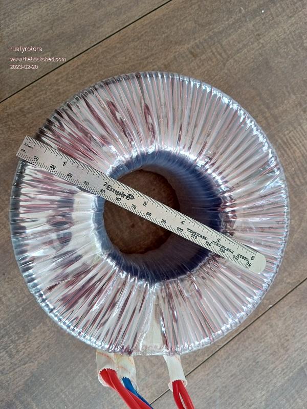
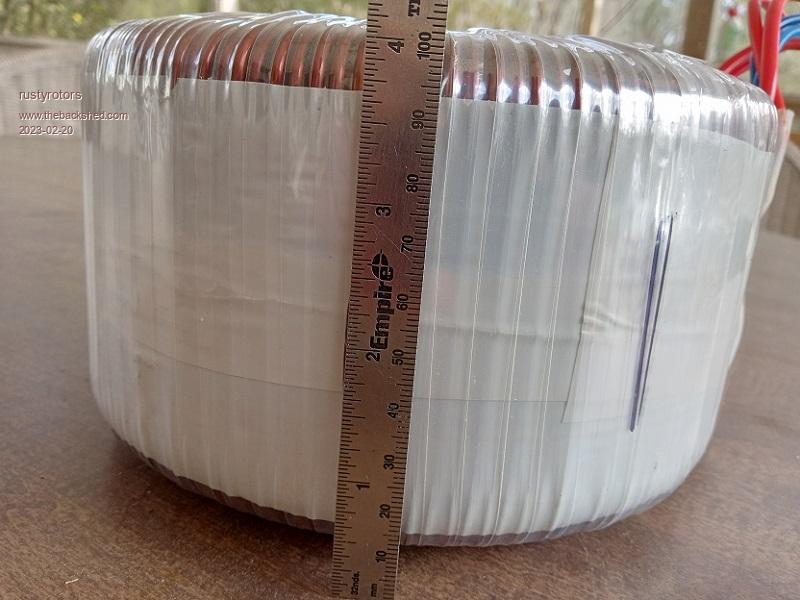
Here are the specs I measured: core area 45x90mm, 36cm2 12AWG windings 146 turns per 115V winding 0.5ohms in series 0.8 Tesla 10W idle at 125V
it took about 18 turns of test wire for a 14v primary. it will probably be good for an easy 2kW. I ordered 30ft reel of 2AWG for the primary.. next have to wind that on and make a choke Edited 2023-02-20 05:24 by rustyrotors
rustyrotors Newbie Joined: 07/01/2023 Location: United StatesPosts: 32
Posted: 07:40pm 19 Feb 2023
Copy link to clipboard
Print this post
if anybodys curious the pinout for the AIMS mosfet board's 10pin IDC connector, not sure if newer ones are different:
1 24V 2 24V 3 gate LOW B 4 gate HIGH A 5 Vs B 6 Vs A 7 gate HIGH B 8 gate LOW A 9 GND 10 GND
analog8484 Regular Member Joined: 11/11/2021 Location: United StatesPosts: 92
Posted: 11:22pm 19 Feb 2023
Copy link to clipboard
Print this post
Nice find but 0.8 Tesla seems a bit low.
Do you mean 2kW at 125v?
rustyrotors Newbie Joined: 07/01/2023 Location: United StatesPosts: 32
Posted: 12:38am 20 Feb 2023
Copy link to clipboard
Print this post
yea most of my loads are 115V, and i figure ebay rating is probably optimistic. the way i think about power handling is how much heat need to be dissipated. the 115V output is just one winding, so less ohms, whereas the 230V output uses both windings in series so double the ohms. assuming the secondary windings can dissipate 100W of heat:
power = 115V * sqrt(100W / 0.25 ohm) = 2300W at 115V power = 230V * sqrt(100W / 0.5 ohm) = 3250W at 230V
5000W at 230V would make 235W of heat, may be too much Edited 2023-02-20 10:40 by rustyrotors
analog8484 Regular Member Joined: 11/11/2021 Location: United StatesPosts: 92
Posted: 06:25pm 20 Feb 2023
Copy link to clipboard
Print this post
That would be quite a bit of heat. Perhaps you could do a temperature rise test during your build.
tinyt Guru Joined: 12/11/2017 Location: United StatesPosts: 431
Posted: 09:50pm 20 Feb 2023
Copy link to clipboard
Print this post
Based on your core area (1.77" x 3.54"), the inner most layer is (1.77 + 3.54) x 2 = 10.62 inches per turn.
The picture shows a wound toroid height of about 4 inches, the outer most layer will be 12.46 inches per turn. I used autocad to get this.
Above values will be shorter since I did not include the rounded corners.
Average of the above is 11.54 inches. Using this average and for the total of 146 x 2 = 292 turns, the total wire length is 292 x 11.54 = 3369 inches or 281 feet.
Magnet wire table for AWG 12 shows 1.588 ohms per 1000 feet. So, winding resistance will be 1.588 x (281/1000) = .446 ohms. Actual value would be lower since I don't know the radius of the rounded corners of each turn.
At 5000 watts and 230 volts, Current is 5000/230 = 21.74A, copper loss will be (21.74 x 21.74) x .446 = 210.8 watts.
At 2500 watts and 230 volts, current is 10.87A, and copper loss will be 52.7 watts.
I could be wrong. Edited 2023-02-21 07:53 by tinyt
Godoh Guru Joined: 26/09/2020 Location: AustraliaPosts: 387
Posted: 04:46am 24 Feb 2023
Copy link to clipboard
Print this post
I bought one of those converters just to see what we get in Oz. It is a Luyuan brand, 5000 va peak 3000 va rating. Well those ratings seem optimistic as usual.
My transformer is 145mm OD over the windings 75mm High 60mm hole in the centre.
I put a turn of wire through and measured around 0.56 volts.
It appears that they are an auto transformer style as there is a common connection between the windings. I measured from one end of the winding 0.52 ohms, and overall resistance was 0.88 ohms.
I looked up some transformers that are available to buy and some that RS components have with a rating of 1kva seem about the same physical size.
I just bought it out of curiosity, it cost $160 delivered, so not bad in price.
I reckon I will put a primary winding on it and see how much idle current it draws and then keep it and build a spare inverter. We have a 2300 watt inverter running our tiny house so it will probably work for that. My workings come out that I will need 28 turns on the primary for out 24 volt system, the Sunyima boards like to have a transformer with a 12 to 14 volt primary. So I will see how it works out. Pete
rustyrotors Newbie Joined: 07/01/2023 Location: United StatesPosts: 32
Posted: 08:37pm 02 Mar 2023
Copy link to clipboard
Print this post
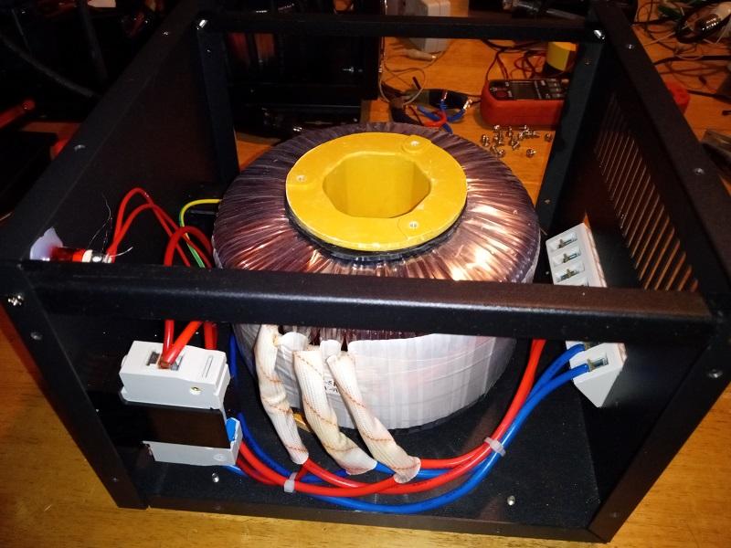
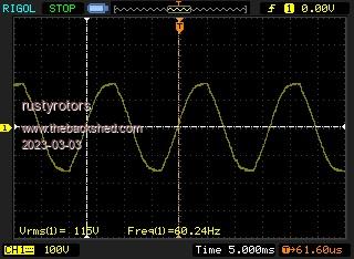
She runs! The choke is 5 turns on a stacked pair of powder iron T250-26 cores. used about 27ft of 2AWG welding cable on the trans primary and the choke. 2uF cap resonates about 90Hz. pulls 18W at idle, fan adds another 2W
yea i need to invest in a proper crimper
Edited 2023-03-03 06:41 by rustyrotors
rustyrotors Newbie Joined: 07/01/2023 Location: United StatesPosts: 32
Posted: 08:56pm 02 Mar 2023
Copy link to clipboard
Print this post
yea i think you are right. actual continuous rating is probably less than half advertised rating. They have very low flux though, good for low idle power draw
Godoh Guru Joined: 26/09/2020 Location: AustraliaPosts: 387
Posted: 10:57pm 02 Mar 2023
Copy link to clipboard
Print this post
Hi Rusty ,hydraulic crimpers are pretty cheap on ebay. Or you could just solder the lugs on. Most times I have had inverters blow up ( Powerjacks) it was from poor connections on the low voltage side. Particularly the input cable connections. It will be interesting to see how your inverter performs on load. The big cable you used for the primary will allow air flow for the transformer so it will be interesting to see how it goes. Pete
rustyrotors Newbie Joined: 07/01/2023 Location: United StatesPosts: 32
Posted: 07:46pm 10 Jun 2023
Copy link to clipboard
Print this post
i bought a proper crimper and redid the lugs. and i finally put a decent load on it, 2500W oven for about 20min, i could not feel any heat increase in the transformer. there is a fan blowing directly on it. i do need to add a second fan for the FETs they got hella hot. i tried my 115V air compressor which pulls about 2500W as well, surges almost 7kw on startup. after about 5 seconds the egs002 shuts down, blinks 4 times, undervoltage warning. i am thinking maybe i need to remove a winding off the primary, get it closer to 13V
Godoh Guru Joined: 26/09/2020 Location: AustraliaPosts: 387
Posted: 12:38am 11 Jun 2023
Copy link to clipboard
Print this post
Sounds like a winner Rusty. Good to see that an old clunker can be used again and that it works well. I had problems with voltage dips when starting my compressor on my 24 volt batteries. I added a capacitor bank in parallel with the batteries and that makes things start really well. No more heavy load slow starts. The capacitors I used were from a bank used to start trains. Memory tells me that they were 500 Farad 24 volt. Half of the 48 volt bank used to start trains. Pete
rogerdw Guru Joined: 22/10/2019 Location: AustraliaPosts: 816
Posted: 06:14am 11 Jun 2023
Copy link to clipboard
Print this post
Far out, where do you find stuff like that? Cheers, Roger
Godoh Guru Joined: 26/09/2020 Location: AustraliaPosts: 387
Posted: 06:30am 11 Jun 2023
Copy link to clipboard
Print this post
Hi Roger, they are probably easier to get in the US than here. Mine are Maxwell 500 farad caps Do a search on ebay or google for Maxwell capacitors, the ones I have came with small balance boards fitted and were shrinkwrapped ready to go. They were 16 volt banks so two banks of them were fine for 24 volt. Pete
rustyrotors Newbie Joined: 07/01/2023 Location: United StatesPosts: 32
Posted: 12:07am 12 Jun 2023
Copy link to clipboard
Print this post
I may try that if i still have trouble! I already have a set of x6 400F supercaps. Im thinking.. 12 of these 400F caps in series would be about 40mohms esr. Would that still be beneficial if my batteries are under 10mohms?
also today i took a lesson from keepis mike and stacked a few more cores for the choke. Took a winding out and used the slack to fit 2 extra t250-52 to the 2x t250-26, powder iron, 5 turns. Waveform cleaned up a lot and idle power is down from 17w to 15w with no fans. Removing the winding lowered the resonance, so had to swap out the 2uF cap for a 1uF. Ordered a 1.1uF to get closer to 90Hz. I will test it out tomorrow on the house
rustyrotors Newbie Joined: 07/01/2023 Location: United StatesPosts: 32
Posted: 09:31pm 13 Jun 2023
Copy link to clipboard
Print this post
it now starts my air compressor easy. i then gave my 2ton hvac unit a try, which normally pulls 2500w continuous on grid, but evidently has a lot of surge. the inverter shuts down immediately. no damage, just the 4 blinks undervoltage. i assume that is caused by voltage at vfb pin dropping too low? maybe the transformer has too much copper loss at that power. i have no overcurrent protection other than circuit breakers. interesting that with a more lossy transformer, you can dead short the output, and the egs002 will just shut down from undervoltage before the FETs blow up


 so it sat unused until recently, i discovered this forum, been reading how to build a diy inverter. my plan is to retrofit it with an EGS002 board for better efficiency, and ill have a nice backup inverter