
|
|
Forum Index : Electronics : Help,I made a mistake- SMD instead of DIP
| Page 1 of 2 |
|||||
| Author | Message | ||||
| vasi Guru Joined: 23/03/2007 Location: RomaniaPosts: 1697 |
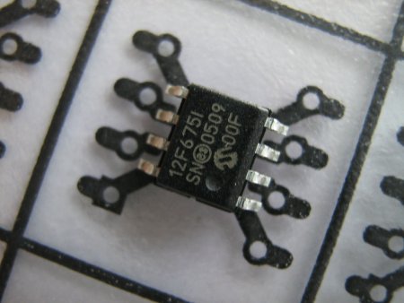
I ordered 4 x PIC12F675 with sockets. I was fooled by the image and not paid attention to notation. 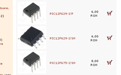
So, I received this (  ) ... ) ...
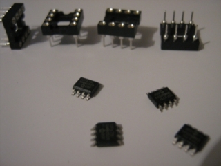
I have no choice and I must make an SMD to DIL adapter. I will use these for DIL pins 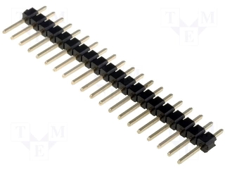
And I made my own design 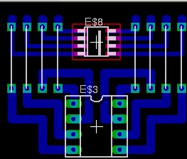
But I found a better one here: 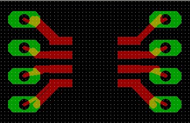
The problems are, I don't know if the second project (or any) can be made with toner transfer and if I can solder the SMD (never did it before) only with an iron solder (I can say I am a little scared - I don't want to loose the chips).Hobbit name: Togo Toadfoot of Frogmorton Elvish name: Mablung Miriel Beyound Arduino Lang |
||||
| davef Guru Joined: 14/05/2006 Location: New ZealandPosts: 499 |
I haven't found these particular packages too much of problem. I bought a temperature controlled iron with a spare 1mm wide tip (made in China) and a flux pen. Solder paste would be better, however I seem to get away with fine solder wire. Make sure you put them on correctly, as they are difficult to remove if you don't use a hot air gun. Toner transfer? I make my negatives just using a standard paper printer and mylar sheeting. Good luck |
||||
| vasi Guru Joined: 23/03/2007 Location: RomaniaPosts: 1697 |
I will have to get it right with a normal 25Watt solder iron, colophony, acetone and normal solder. I checked the second design and is not good for what i have (the "A" variant). "B" variant is ok but the "portability" is broken. At least, this way can be usable. Lesson learned. 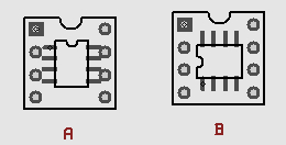
Hobbit name: Togo Toadfoot of Frogmorton Elvish name: Mablung Miriel Beyound Arduino Lang |
||||
| GWatPE Senior Member Joined: 01/09/2006 Location: AustraliaPosts: 2127 |
Hi vasi, I don't see any problems with just bending pins 1,4,5,8 a little away from the adjacent pins. The SMD devices you will probably not use for production. You should be able to solder pins 2,3,6,7 directly to the socket. You then can just solder 1.4.5.8 with short links. This will give a close to std DIL pkg. Gordon. become more energy aware |
||||
| vasi Guru Joined: 23/03/2007 Location: RomaniaPosts: 1697 |
 He, he, thank you Gordon, He, he, thank you Gordon,
this is a good solution. Didn't saw it that way. Chips are so little and look fragile. Now i can continue with the standard design. Vasi Hobbit name: Togo Toadfoot of Frogmorton Elvish name: Mablung Miriel Beyound Arduino Lang |
||||
| GWatPE Senior Member Joined: 01/09/2006 Location: AustraliaPosts: 2127 |
On the picaxe PICLOG PCB I made, I allowed provision for SMD and DIL pkg. The DIL pkg just just needed the legs moved out a little, and fitted the plated holes. If the SMD device used, this just soldered normally. Gordon. become more energy aware |
||||
| Dinges Senior Member Joined: 04/01/2008 Location: AlbaniaPosts: 510 |
Vasi, I came across this (http://elm-chan.org/docs/wire/wiring_e.html) a while ago. It may interest you. A few simple techniques to work with SMD ICs without having to etch printed circuit boards. Peter. |
||||
| vasi Guru Joined: 23/03/2007 Location: RomaniaPosts: 1697 |
Thank you Peter, It looks very interesting. Bookmarked! Very interesting this "wiring pen" technique. Hobbit name: Togo Toadfoot of Frogmorton Elvish name: Mablung Miriel Beyound Arduino Lang |
||||
| GWatPE Senior Member Joined: 01/09/2006 Location: AustraliaPosts: 2127 |
Hi dinges, the wiring pen technique has probably been used by most prototypers. I indeed used this same method when I could see unaided. [probably 20years ago now] I used it for digital connections, between IC's as well. This has limited use in analogue prototypeing where you may have to change component values. I hardly use leaded components now, so this makes it harder with point to point wiring as well. Gordon. become more energy aware |
||||
| Dinges Senior Member Joined: 04/01/2008 Location: AlbaniaPosts: 510 |
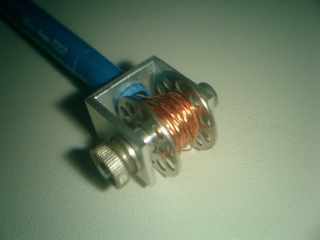
[quote=Gordon]the wiring pen technique has probably been used by most prototypers. I indeed used this same method when I could see unaided. (probably 20years ago now) [/quote] I know Gordon, it's nothing new. I've included a few pictures of my DIY wire dispenser below. At the time they asked 50 guilders for one. Seemed ridiculously expensive to me for something as simple as that, so I made my own out of a Pentel 0.7mm automatic pencil and some other odds and ends. The spool is the thingy that normally goes in a sewing machine (under the needle). My only problem with it is that it holds too little wire, I need to make a bigger spool for it someday. 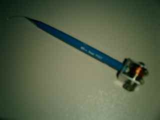
What was new (to me at least) in that site is how he used such techniques for SMD too. I've routinely used SMD resistors and capacitors on perf board (e.g. SMD capacitors fit *perfectly* between the legs of a DIL IC; SMD pull-up/down resistors can be installed very conveniently too that way). But the guy in the link seems to take it all one step further and also wires up SMD ICs like that. Even the ones with smal lead-spacing... Vasi, in the past I've repaired a notebook's CFL-inverter (SMD) in the field with a 40W (!) soldering iron with a LARGE tip. More the kind you'd use for plumbing or soldering valve equipment. At one moment I noticed a SMD capacitor stuck to the tip... not knowing *when* or *where* it came off the board  . Needless to say, sweat was pouring from my forehead... but in the end I got it all together again (it even worked!). So I suppose there is some margin for error or sloppy workmanship. . Needless to say, sweat was pouring from my forehead... but in the end I got it all together again (it even worked!). So I suppose there is some margin for error or sloppy workmanship. 
Normally I use a 25W iron (with fine tip) for SMD. Works fine for me. Of course, if I'll ever come across a hot-air soldering station for little money I won't turn it down. But a normal iron works fine too, with some care and proper technique. I find thin soldering tin-wire is important though; I use 0.46 mm flux-core wire for SMD (.8 mm for through-hole components). I'd say, dive in and give SMD a go. Once you've played with it a few times and developed the techniques that work best for you, you'll not think twice about using SMD again in your own projects. Though I still vastly prefer through-hole components over SMD for experimental work or prototype circuits (and just about everything I build is a prototype/one-off anyway...) Peter. |
||||
| Dinges Senior Member Joined: 04/01/2008 Location: AlbaniaPosts: 510 |
...And if you don't have or can't find such thin tin wire, you can also add excessive tin (even to the point that it shorts the pins together) and then remove the excess with de-soldering braid. In fact, I get my best-looking SMD soldering joints that way, with only a little amount of tin left (of course, don't suck it entirely dry). Peter. |
||||
| vasi Guru Joined: 23/03/2007 Location: RomaniaPosts: 1697 |
Thank you guys, I have more courage now. I don't have such a thin wire but I think I can find some wire with proper dimensions. I will keep you posted. Hobbit name: Togo Toadfoot of Frogmorton Elvish name: Mablung Miriel Beyound Arduino Lang |
||||
| Tinker Guru Joined: 07/11/2007 Location: AustraliaPosts: 1904 |
...... Peter, have you considered building your own hot-air gun? It would be easy for a bloke with your talents 
I built a relatively crude version of a hot air gun from odds & ends I found in my junk box, mainly to use it for unsoldering sm devices. It actually worked. The tip is the tricky bit, its hard to make a tiny heating coil and focus the hot air to a very small area. Klaus |
||||
| vasi Guru Joined: 23/03/2007 Location: RomaniaPosts: 1697 |
I had time to make prints on transparencies. Is more easy to design a pcb directly for smd but I want to reuse them (replace them in future with 12F629 for stepper drivers) because of their A/D converter. So it must be in a 8 pin socket. 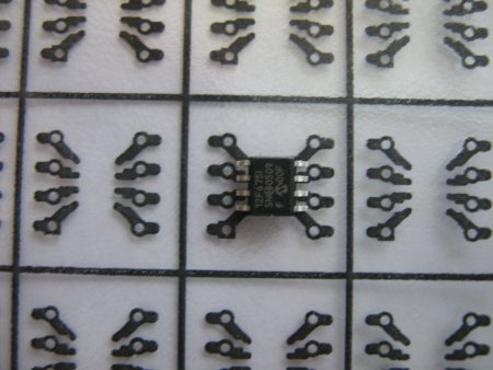
Hobbit name: Togo Toadfoot of Frogmorton Elvish name: Mablung Miriel Beyound Arduino Lang |
||||
| vasi Guru Joined: 23/03/2007 Location: RomaniaPosts: 1697 |
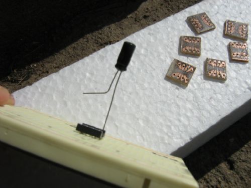
Adapter is ready, not soldered the chip yet... This is my intention: 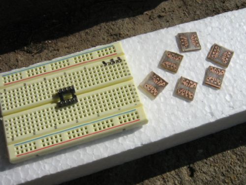
Ready to convert my SMD pics ... 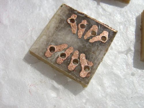
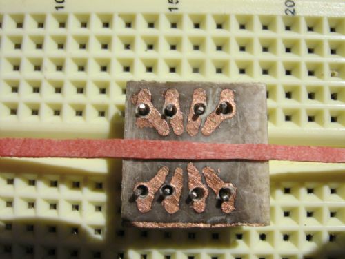
Ferric chloride was expired and lead to long time copper exposure. Also, the drill is 1 mm diameter . I applied a protective layer of rosin (which, I hope, will also help to solder - the risk is to float the trace if layer is too thick or, false soldering/connection ... ).
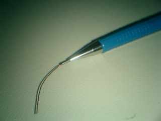
Tested few components to see what type is my pin donor. I selected the condenser but... 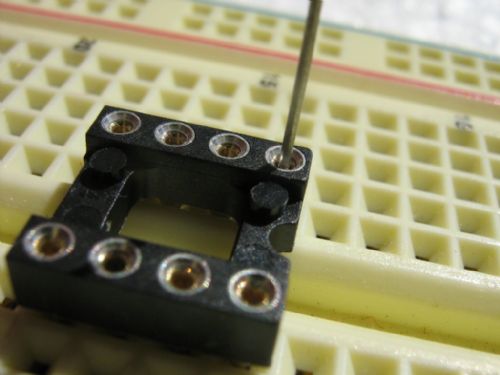
.. the macro photo revealed that the pin is too thin. 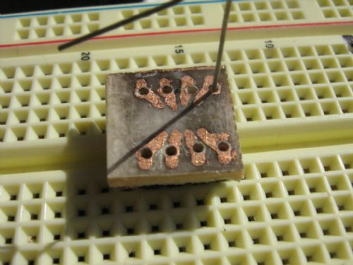
This is how pins will be inserted, then cut them to right dimension and soldering. Definitely, the pin is too thin... will try with a 0.5 watt resistor... Next time I will open my eyes before any order... Hobbit name: Togo Toadfoot of Frogmorton Elvish name: Mablung Miriel Beyound Arduino Lang |
||||
| Dinges Senior Member Joined: 04/01/2008 Location: AlbaniaPosts: 510 |
Vasi, I'm not sure why you want to use both an 8-pin DIL socket together with your SMD-to-DIL adapter, but if you want to do it like that, try finding a different 8-pin DIL socket: not the one you have now, with the turned pins, but the cheaper variant with the pin-sockets with spring action (http://www.voti.nl/ir-3/pics/dil14-big.jpg); these will be much less critical w.r.t. wire size. Peter. |
||||
| vasi Guru Joined: 23/03/2007 Location: RomaniaPosts: 1697 |
Well, few reasons. I really want to reuse them (many times) so, the adapter will not be soldered to pcb. I'm afraid using only the adapter, is not sufficiently resistant. The copper trace is very thin. The pin is soldered only on one side. If I press the adapter in a socket (remember, as many times as possible), the risk is flaking routes (I did not ordered that kind of pins, as in my first post - next time ...). So, I will waste a socket and the packet will be rock solid. Of course that type of socket is better from pin size point of view but did not find it in that store where I ordered my components - or I wasn't able to find it. Plus, mine is a resistant socket and fit for "many times use - inserting/removing". But the first reason is my lack of skills, for sure Hobbit name: Togo Toadfoot of Frogmorton Elvish name: Mablung Miriel Beyound Arduino Lang |
||||
| GWatPE Senior Member Joined: 01/09/2006 Location: AustraliaPosts: 2127 |
Hi Vasi, you have made a PCB adapter. This is not really necessary. The SMD will fit across the DIL socket you have shown in the manner I have described above. You may require links to 2,3, or 6,7 depending on your soldering technique and initial placement on the socket. Gordon. become more energy aware |
||||
| vasi Guru Joined: 23/03/2007 Location: RomaniaPosts: 1697 |
Hi Gordon, I don't have a very steady hand.. I found a way to keep the pcb steady - with elastic. I will try first this way. On the next trial, I must find/make something to fill that central hole from socket, to use as a support for SMD. Then, I can keep it steady with elastic and use pins from condenser as links ... If is working for me, the last two pics will be soldered like this one (as you said). This variant will save pcb, acid, toner, electricity and time ... If not, pcb adapter is the solution for me... hope will post tomorrow a photo ... I said I'm burning to test the ICSP programmer and to program my first "raw" (not PICAXE prepared) PIC? Hobbit name: Togo Toadfoot of Frogmorton Elvish name: Mablung Miriel Beyound Arduino Lang |
||||
| vasi Guru Joined: 23/03/2007 Location: RomaniaPosts: 1697 |
I did it! 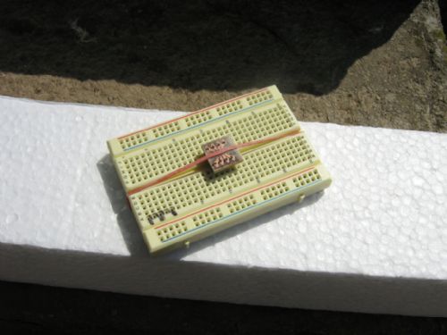
After fixing the pcb, soldered the pins and traces, then placed the PIC, fixed with elastic and soldered... 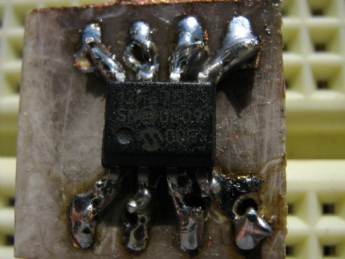
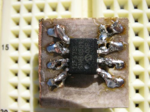
Well, it was easy.. only the fear is big at the beginning  . I used a 0.5mm rosin flux cored solder. . I used a 0.5mm rosin flux cored solder.
I will try to read the PIC with my programmer and then, will try to solder the other PIC's directly to socket. ------------------ I put too much solder on traces and positioning the PIC was a little hard on those solder bulbs... next time will be better... Hobbit name: Togo Toadfoot of Frogmorton Elvish name: Mablung Miriel Beyound Arduino Lang |
||||
| Page 1 of 2 |
|||||
| The Back Shed's forum code is written, and hosted, in Australia. | © JAQ Software 2026 |
