
|
|
Forum Index : Electronics : AC Motor from a shredder machine
| Author | Message | ||||
| irishron40 Senior Member Joined: 22/09/2014 Location: IrelandPosts: 254 |
Hello everyone I have a question about an AC moter from a fellowes shredding machine. It is from a FELLOWES 225Ci shredder This motor is normaly wired onto a circuit board , but as I dont have it or need it I need to hot wire it for my metal bending machine from the windingsthere are 3 wires red black yellow. If I put 220VAC onto the red and black it does work , but if Disconnect the power and re power it again it changes direction. I just wonder is this yellow wire for optional direction as I do know that it was possible to change direction when connected to circuit board. Any advise welcome. Thanks Ron Edited 2023-04-30 14:14 by irishron40 |
||||
| rogerdw Guru Joined: 22/10/2019 Location: AustraliaPosts: 955 |
It's a bit hard to read the label but doesn't it say 120V? It also mentions a 50uf 300V capacitor, so I suspect that will help with the starting and direction. Hopefully someone who's expert in motors will pipe up soon.  Cheers, Roger |
||||
| irishron40 Senior Member Joined: 22/09/2014 Location: IrelandPosts: 254 |
thank you rogerdw This picture is not my actual motor Mine is rated 220vac I do need to be able to select direction thank you ron |
||||
| Godoh Guru Joined: 26/09/2020 Location: AustraliaPosts: 675 |
The motor in the photo ( you said it was not your one) does not look like there is room for a starting switch. So it either has an external starting switch that supplies power to the starting winding, in this case it is most likely the yellow wire. There may also be an external capacitor that is wired in circuit with the starting winding to give it more torque. My guess is that there are two capacitors in the machine it came from. One high capacitance ( around 150 to 250 microfarad) that is the starting capacitor. And one lower value ( around 10 to 15 microfarad) capacitor that is in circuit when the larger cap is switched out after it starts. Pete |
||||
| Godoh Guru Joined: 26/09/2020 Location: AustraliaPosts: 675 |
Try this. Measure the resistance from the Yellow wire to the Red, and the Yellow wire to the Black. It looks like one end of the starting winding is connected internally. Most likely to the Red. So test from yellow and see what readings you get. You should get something like 20 to 30 ohms through the winding but it may be less. Lets say the winding is connected to the Red on one end and you get a resistance reading to the Yellow when testing. Then connect a capacitor ( 10 uf motor run cap) to the yellow and to the Black. Connect the black and red to the mains and see if it starts then. Pete |
||||
Madness Guru Joined: 08/10/2011 Location: AustraliaPosts: 2498 |
It needs a capacitor, the label in the photo says 50uF. There are only 10 types of people in the world: those who understand binary, and those who don't. |
||||
| phil99 Guru Joined: 11/02/2018 Location: AustraliaPosts: 3317 |
The difficulty is the motor in question is 220V and the one in the photo is 120V, so the required cap. will be lower capacitance but higher voltage. @irishron40 can you post a photo of the label on the one you have? Just a guess but 20 to 30uF 440VAC is possible. Edit. So far the assumption has been that red and black go to active and neutral but there are no standard colours for motors built into equipment. Measure the 3 resistances between the leads. For a motor that is intended to run in one direction only:- The lowest resistance is probably the main winding and connects to active and neutral. The capacitor will then connect between the two with the highest resistance. For a reversible motor:- The two windings will have the same resistance. The capacitor will connect between the two wires with the highest resistance. The neutral can connect to the remaining wire. The active can connect to either end of the capacitor. Clockwise if connected to one end, counter-clockwise if connected to the other end. The motor must not be spinning when reversing or momentum may override the effect of the capacitor. Edited 2023-05-01 09:39 by phil99 |
||||
| irishron40 Senior Member Joined: 22/09/2014 Location: IrelandPosts: 254 |
Thank you and sorry for late reply as my health took a bad turn. I took some details. motor is from a fellowes 225Ci shredder Motor is 240vac The capacitor that came with it is 450VAC / 14 uF From motor 3 wires ( Red . Black . Yellow) resistance between : red and black = 9.5 ohm Yellow and red = 18.3 ohm yellow and black = 27.6. should I wired it this way? 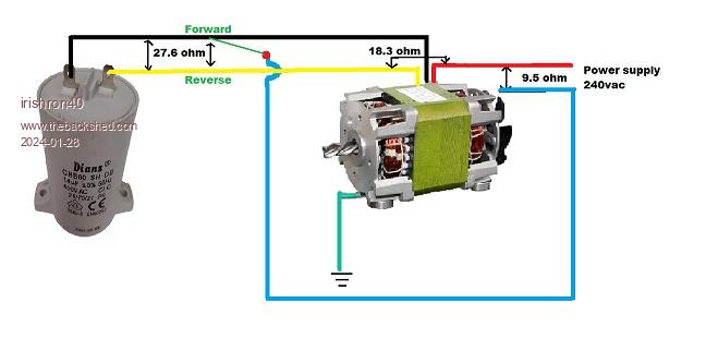 many thanks ron Edited 2024-01-28 21:18 by irishron40 |
||||
| phil99 Guru Joined: 11/02/2018 Location: AustraliaPosts: 3317 |
Your drawing appears to be correct. The resistance values indicate reverse will deliver lower torque than forward but it should run. Forward:- Red to supply active Black to supply neutral Capacitor from black to yellow Reverse:- Red to supply active Yellow to supply neutral Capacitor from black to yellow |
||||
| irishron40 Senior Member Joined: 22/09/2014 Location: IrelandPosts: 254 |
Thank you Phil99 |
||||
| irishron40 Senior Member Joined: 22/09/2014 Location: IrelandPosts: 254 |
Hi phil99 . I have it working perfectly and am great full for the help I received . just wondering is there a way to controll the speed on an AC motor? thank you. ron |
||||
| phil99 Guru Joined: 11/02/2018 Location: AustraliaPosts: 3317 |
For an induction motor it depends on how much torque is needed at low speed. A fan needs very little torque at low speed so a simple Triac based speed control may work. It's essentially a light dimmer modified to work with an inductive load. If more torque is needed a Variable Frequency Drive controller is needed. Much more complicated. Triac speed control Edited 2024-02-05 21:53 by phil99 |
||||
| The Back Shed's forum code is written, and hosted, in Australia. | © JAQ Software 2026 |
