
|
|
Forum Index : Electronics : Battery Cell Active Balancer
| Author | Message | ||||
| Solar Mike Guru Joined: 08/02/2015 Location: New ZealandPosts: 1228 |
Thought I would have a play with "Active Battery Cell" balancers; having made several dissipative load types in the past; active types are a natural progression. Look here for a great You Tube video on the subject. I need 3 or 4 of these for some 4 cell 50 Ah Lifepo4 12v batteries and several 48 volt banks of lead carbon 6 volt batteries. Looking online there is a plethora of inexpensive addon modules that would seem to do everything required; I have purchased a couple of the switched capacitor and inductive voltage shuffle types to play with. Cannot say I'm impressed with what's available at the low end of the price range and the quality of components is totally unknown. They all require huge disparity in cell voltages to make any large balancing current and are not really autonomous, ie they are working continuously and some require manual input to turn off the balancing when its not required.... I would not really trust any of them on an expensive battery bank. So a bit of DIY is called for, here is the basic dia for a simple concept of removing energy from the highest battery cell and adding to the lowest cell using a large value low esr capacitor bank. 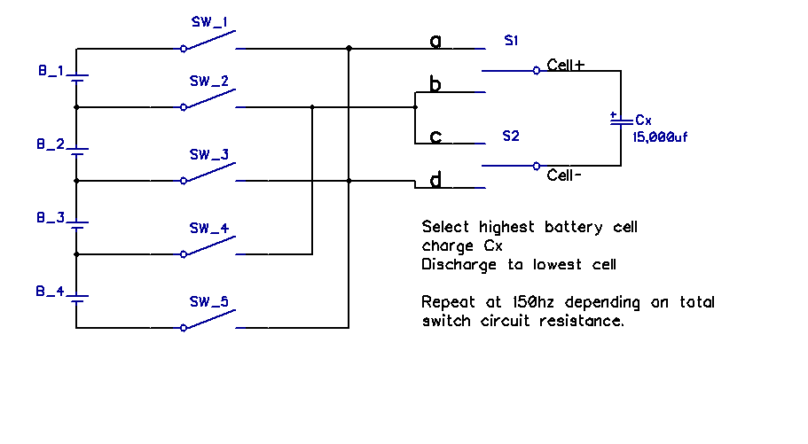 Large low esr cap Cx is charged from the highest cell and discharged into the lowest, achieved by switching the switches in correct sequence order. In practice the switches are back to back mosfets (dual device mosfets) each with an isolated gate drive, there is a time RC constant with Cx and the mosfet drain-source resistance, this determines the most efficient switch frequency. As cell voltages converge, balance current will naturally reduce to the point when balancing functionality is turned off. With Lifepo4 banks balancing opportunity (high Side) will only really take place in the high voltage knee 3.4 - 3.6v; I limit my cell voltages to 3.5v max. Have started drawing out a schematic, it looks complex, but all devices purchased from LCSC electronics are relatively inexpensive. I will use a 28pin Picaxe to drive the mosfets. 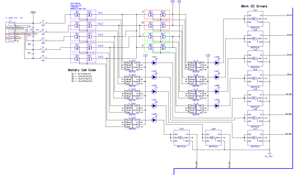 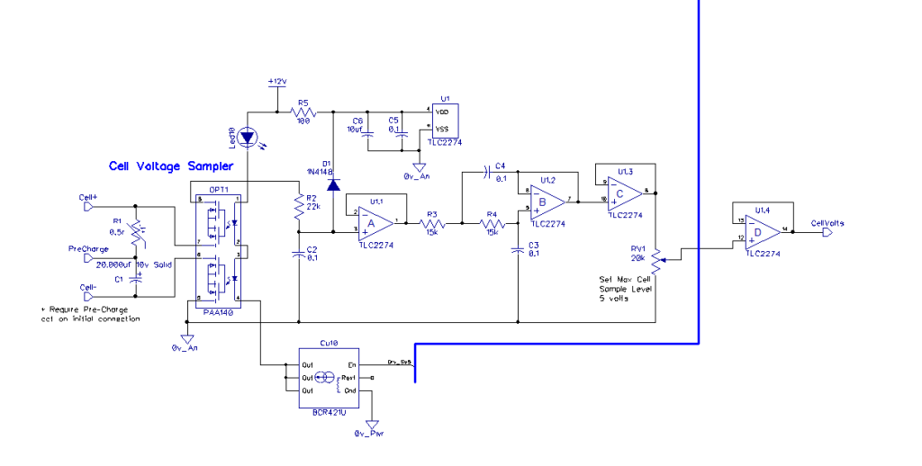 More to come.... |
||||
| Solar Mike Guru Joined: 08/02/2015 Location: New ZealandPosts: 1228 |
OK basic requirements for the project: Read individual cell voltages and transfer charge from the higher to lower cell directly. Automatically turn off transfers and switch to\from standby mode as required. Presets for Cell min, max and balance start voltages. Measure battery bank temperature sensor. Separate pull down outputs to external PV\Charger input, output load relay or switch. Alarm output. Simple serial data output for cell information. Effectively a simple BMS implementation for 4 - 8 battery cells, lifepo4 or 6v Lead Carbon. Mike Edited 2023-05-10 19:20 by Solar Mike |
||||
Revlac Guru Joined: 31/12/2016 Location: AustraliaPosts: 1282 |
Looks good Mike, I have tried to set My Daly BMS to start balancing at 3.4volt, so far it has refused to be set at 3.4v, other than that it has been working. I know its a waste balancing before 3.4v per cell on lifepo4. I was looking at some Lead Carbon Batteries for a friends solar setup, Are they very fussy with voltage when near fully charged? Cheers Aaron Off The Grid |
||||
| Murphy's friend Guru Joined: 04/10/2019 Location: AustraliaPosts: 678 |
Yes, it would work for 4 cells or so. I tried that idea, using super capacitors, with 16 cells and it was way too slow to do any meaningful balancing. Its the small voltage difference between the cells, a few tenths of Volt at most, that make it difficult for the capacitor to accept meaningful charge in the time allocated. I'm now using Warpspeed's inductive balancer that copes much better with 16 lithium cells of different vintage. |
||||
| Solar Mike Guru Joined: 08/02/2015 Location: New ZealandPosts: 1228 |
Yes, Float voltage is 2.25v cell and 2.3v bulk charge (25 degrees C) multiply X3 for 6V batteries for the 6REXC300 types we are using. Design life of 20 years, so great for standby operations, very low self discharge; however they are still lead and have a long tail charge time to get fully topped up. They are heavy and take up a lot of space, think I prefer Lifepo4 cells as they are lighter, smaller, more efficient and faster charging. Mike |
||||
| Solar Mike Guru Joined: 08/02/2015 Location: New ZealandPosts: 1228 |
I agree 16 cells would be pushing it using capacitor balancing. I will have a switch option where the large capacitor goes to allow for adding a boost fly-back converter board that ups the voltage to bank level; this will suck up to 10 amps from a high cell and discharge into the main bank. Edit: just noticed an error in the schematic, all the dual mosfet drivers gate drivers are wired wrong, replacing them with much less expensive TLP3906. Will update with another schematic when its done. Cheers Mike Edited 2023-05-12 15:07 by Solar Mike |
||||
| Solar Mike Guru Joined: 08/02/2015 Location: New ZealandPosts: 1228 |
Finally found some time to draw out the schematic and do a pcb, I'm going to have a play with an 8 cell balancing BMS design; will be interesting to see what difference having either a capacitor array 20,000uf discharging from the highest voltage cell to the lowest; or using a small boost inverter discharging the highest cell into the whole battery bank. I have allowed for both options with the pcb, the boost fly-back inverter and the cap array sit on separate pcb's. A small separate display pcb driven by serial data can show balancing status. Main PCB 170 x 120mm: 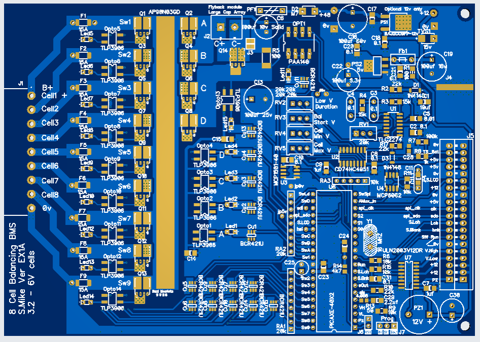 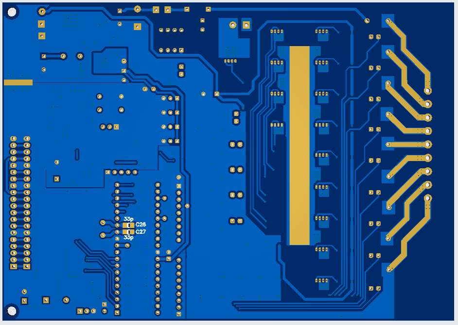 Display 60 x 57mm: 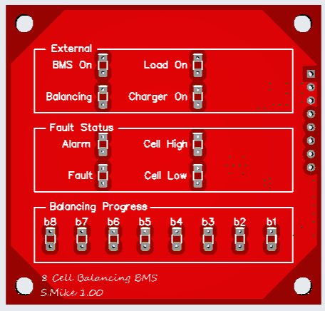 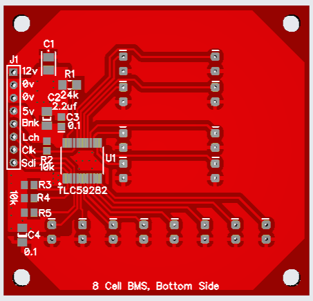 Schematic: I drew out 99% of the circuit then split it out into the main BMS and Led display boards, most cpu IO out lines have a 20k pulldown resistor (array) not shown on the schematic, also not shown are the common Picaxe programming bits or crystal. BMS_Schematic.pdf Cheers Mike |
||||
| The Back Shed's forum code is written, and hosted, in Australia. | © JAQ Software 2026 |
