Notice. New forum software under development. It's going to miss a few functions and look a bit ugly for a while, but I'm working on it full time now as the old forum was too unstable. Couple days, all good. If you notice any issues, please contact me.
Murphy's friend Guru Joined: 04/10/2019 Location: AustraliaPosts: 678
Posted: 08:57am 11 May 2023
Copy link to clipboard
Print this post
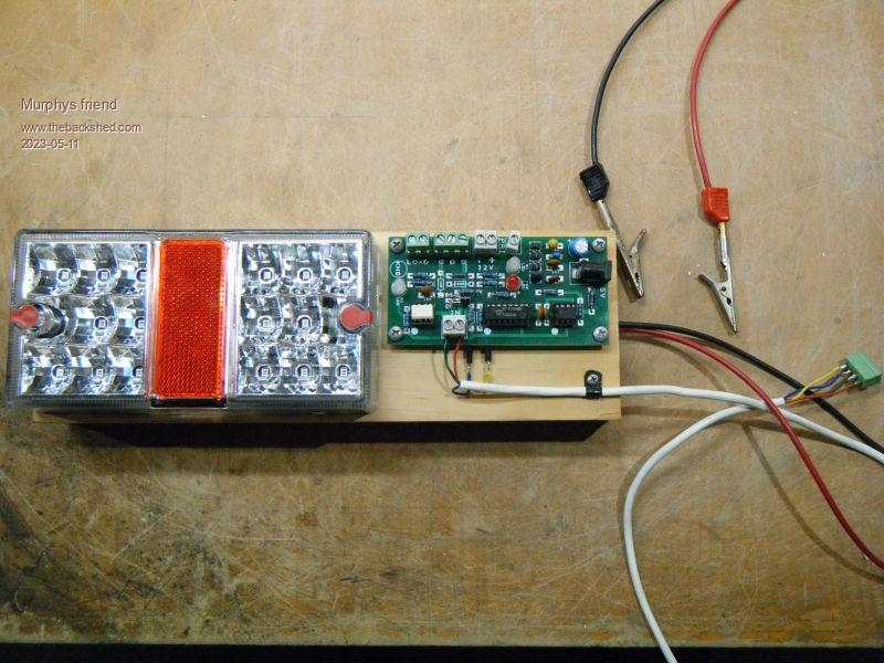
I made this gadget to assist in finding an elusive intermittent fault in my small inverter.
It might also be useful to those who are not electronic engineers (with all the fancy test equipment) or first inverter builders.
It will work with driver stages that use the isolated DC/DC power modules for the driver chips, such as the nano inverter or the warp inverter.
Basically, the inverter's control board is disconnected from the drivers and they instead connect to the gadget.
The other requirement is to disconnect the primaries from the heatsinks and connect the modified LED trailer light combo wires at the heat sinks instead.
A 5V power source is required for the gadget as well.
The gadget will do the following:
It will turn on the half bridge drivers (just as the control board does but much slower) so that the trailer light brake & indicator LED's flash alternatively.
This is a very safe way to check the correct operation of the drivers and power mosfets as only about 4W are switched, not enough to blow up anything .
A wrong connection or malfunctioning part becomes very obvious if the LED's do not flash alternatively.
There are 4 selectable ratios for the flashing, the faster ones are good to observe the mosfet switching on an oscilloscope.
I have also included two more functions, one to check individual mosfets by letting them turn on/off a lamp load repetitively, the other to check the driver chips. Those two functions require a 12V supply as well as the 5V.
The PCB in the picture below has been modified, I have the updated Gerbers available for those who want to build this. You get 10 boards for the price of 5 since two boards are laid out on a 100x100mm PCB.
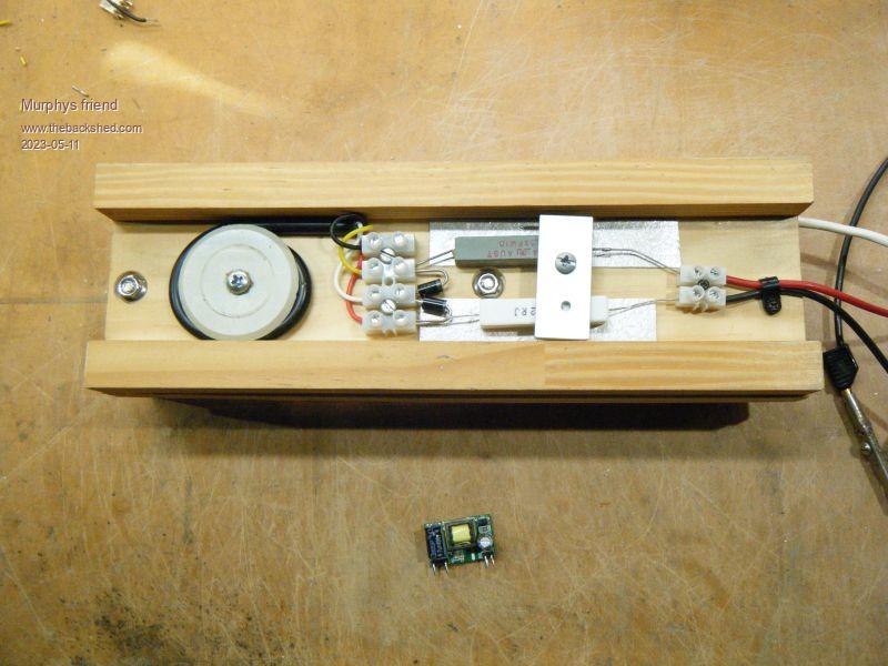
So what was the elusive fault? It is shown at the bottom of one picture. I have more than two dozen of these DC/DC's here, used in various projects and this is the first & only faulty one I came across.


 .
.