
|
|
Forum Index : Electronics : "Half cut" inverter
| Author | Message | ||||
| MichaelCrex Newbie Joined: 17/05/2023 Location: PolandPosts: 8 |
As my current inverter turned out to be too small (3 kW) and after reading a lot from this respectable forum, I've decided starting a work on my new DIY LF inverter. First things first, transformer. 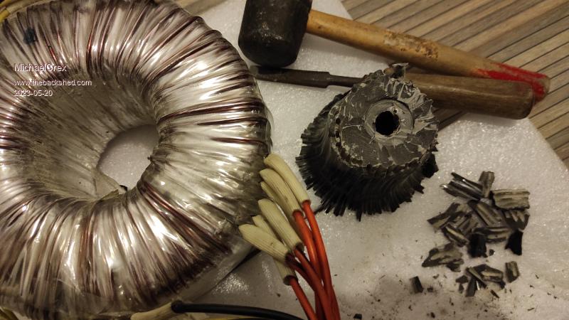 I want to make it of two of these toroids (20 cm in diameter, 18 kg weight) combined into one big one. Edited 2023-05-20 02:40 by MichaelCrex |
||||
| MichaelCrex Newbie Joined: 17/05/2023 Location: PolandPosts: 8 |
Here I'd like to share and discuss an idea that I came across a bit by accident while looking for a way to better balance the currents of the body diodes in the FET bridge (lots of reactive power). The idea is quite similar to what we are currently seeing as the standard design of almost all PV modules. They use half cut cells and are split in half too. It turned out to be a brilliant idea that improves almost all parameters of the PV module (including economic ones) with almost no additional costs and effort. Here is a simple drawing that shows what I mean: 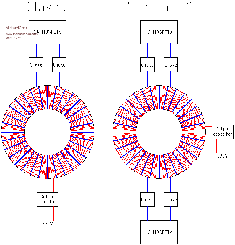 It seems that with very little effort the FET bridge, chokes and the primary winding can be split in half. Of course, you can split it into three, four and more (the principle is the same) but it requires much more effort because the geometry doesn't help with more splits, as in the case of PV modules. Similar ideas were presented here, but probably no one proposed dividing the primary winding into several non-overlapping sections. These sections are intended to behave as connected in parallel in case of symmetrical currents and introduce different resistive voltage drops and leakage inductance in the case of lack of symmetry. In my case, calculations shows that winding two non-overlapping primaries this way comes by itself, so I plan to go this way and if it turns out to be a mistake, withdraw from this idea by connecting both sections in parallel. Edited 2023-05-20 03:27 by MichaelCrex |
||||
| KeepIS Guru Joined: 13/10/2014 Location: AustraliaPosts: 1345 |
Hi, nice to see you on this great forum, you are correct, there have been discussions on doing something similar. I know forum member "wiseguy" was giving this some thought when he was designing his Inverter Power board module. I will be following this with interest, BTW like your video and your current installation. . Edited 2023-05-20 08:43 by KeepIS It's all too hard. Mike. |
||||
| analog8484 Regular Member Joined: 11/11/2021 Location: United StatesPosts: 87 |
So, this needs twice the primary winding wires? But half the gauge? Would a larger toroid hole be required? |
||||
| rustyrotors Newbie Joined: 07/01/2023 Location: United StatesPosts: 29 |
what would be the advantages? |
||||
| MichaelCrex Newbie Joined: 17/05/2023 Location: PolandPosts: 8 |
Thanks. I'm following your work. Your inverter thread contains really unique observations. |
||||
| MichaelCrex Newbie Joined: 17/05/2023 Location: PolandPosts: 8 |
Unlike most people here I'm planing a 24V unit. I very like lead acid batteries, especially forklift ones (I'm in the process of buying a few used ones) but don't like 24 cells in series. If you carefully split your system, there can be only two points where all this currents adds up. So if you split the primary in half you obtain effectively the same number of turns and the same current as at 48V. The same applies to the FET bridges if you are able to separate them properly. I think the non overlapping primary sections can help with this separation. First because each FET bridge will work with a separate resistance of its primary section. Second, each section will be tightly coupled only with the half of the secondary and weakly coupled with the other windings. Consider what it all looks like when one transistor for various reasons, always turns on first before other 3-5 "paralel" ones. It sees only its own choke with its 2x resistance, its own section of primary winding also with its 2x resistance and extra leakage inductance which disappears only whet the other bridge also turns on. The best separation will be with two separate transformers but one big toroid has its advantages. I'm seriously considering splitting all this into three or even four. With one big toroid its only the thick primary you need to arrange properly. It's all just theory for now... |
||||
| MichaelCrex Newbie Joined: 17/05/2023 Location: PolandPosts: 8 |
The basic component of my inverter, four FET half bridge: 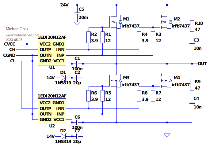 In the first prototype there will be four of them, all controlled by the EGS002 board, but with IR2113 soldered out. 1EDI20N12AF is an isolated 4A MOSFET driver. Powered from 14V to allow testing 6A IGBT drivers (1EDC60H12AH). Edited 2023-05-23 04:11 by MichaelCrex |
||||
| nickskethisniks Guru Joined: 17/10/2017 Location: BelgiumPosts: 409 |
I think you will create a lot of interest, good luck! One thing that will be a challenge is to create 2 equal primaries (24V windings). A "cool" experiment on my list is to do the same as you propose but with 1 primary, so connecting the bridges in parallel but after the chokes. The choke should help with sharing the current. This might be a solution for the side effects occurring when paralleling lot's of mosfets. |
||||
| MichaelCrex Newbie Joined: 17/05/2023 Location: PolandPosts: 8 |
There were obvious errors in the half bridge schematic. Below is the revised version with some additional elements that allow to simulate it in a some way in the LTspice. 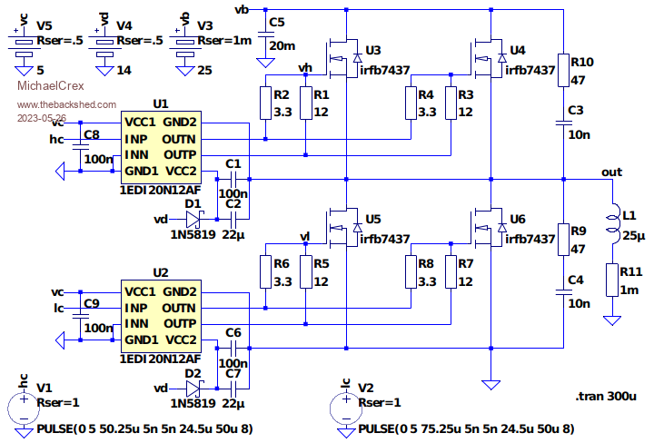 Below is the plot from the simulation. Take it with a grain of salt. It has only such a value that proves there are no major errors in the schematic. The current in the choke is probably reasonably well simulated (think of it as a short circuit on the transformer secondary and the other half of the bridge is the 50 Hz one, and now provides 0V on its output). 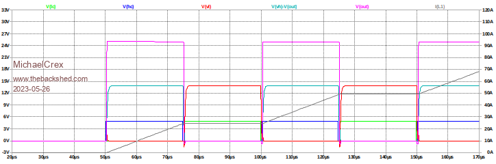 Zoom. 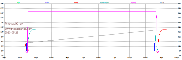 Edited 2023-05-26 04:06 by MichaelCrex |
||||
| MichaelCrex Newbie Joined: 17/05/2023 Location: PolandPosts: 8 |
I've just bought 8 sendust cores for two chokes (26.42 PLN = 6.32 USD each). The plan is to build two chokes, one for each "half-inverter". One choke on each 23 kHz leg. The 50 Hz legs connected directly to the toroid. Datasheet. Calculations: Al = 85 nH/(N*N) Le = 19.61 cm (effective magnetic path length from datasheet) H50%u = 100 Oe (magnetizing field at which u drops to 50%) M = 4 (number of cores) N = 9 (number of turns) Imax = 150 A (assumed peek DC current of the choke) Hmax = 0.4 * PI * N * Imax / Le = 86.5 Oe < 100 Oe L = Al * M * N * N = 27.5 uH The peek currents of two "half-inverters" add up to 300A and with such a load, the inductance of each choke should not fall below 27.5 uH * 0.5 = 13.8 uH. I've also considered the MS-226060 cores that Mike (KeepIS) uses in his inverter but did chose MS-301060-2 because of bigger hole. Edited 2023-06-06 03:49 by MichaelCrex |
||||
| MichaelCrex Newbie Joined: 17/05/2023 Location: PolandPosts: 8 |
Three useful charts for sendust cores. 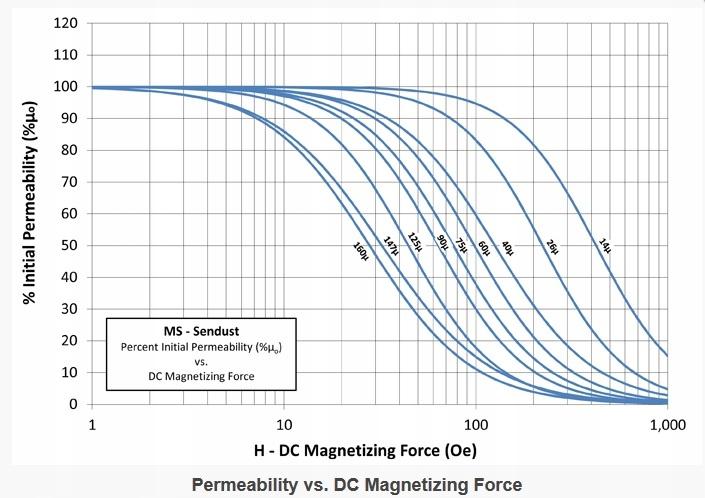 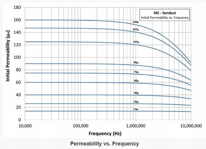 The last three digits of the part number indicate the permeability of the material. For example MS-301060 and MS-226060 are both 60u cores. As you can see this material can work up to 1MHz but for high flux densities the max. usable frequency is about 50 kHz because of the losses. 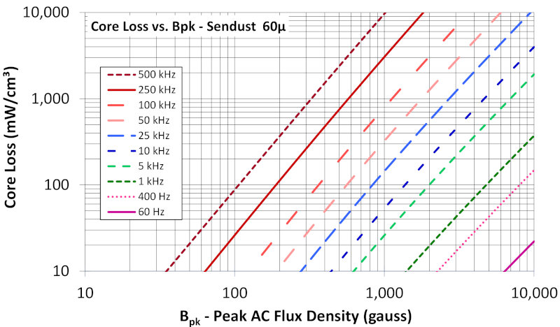 In our case the high flux is for 50/60Hz and with enough inductance the 20 kHz current and its harmonics should be small. Edited 2023-06-06 21:21 by MichaelCrex |
||||
