Home
JAQForum Ver 20.06
Log In or Join  
Active Topics
Local Time 17:40 25 Apr 2024 Privacy Policy
Jump to

Notice. New forum software under development. It's going to miss a few functions and look a bit ugly for a while, but I'm working on it full time now as the old forum was too unstable. Couple days, all good. If you notice any issues, please contact me.

Forum Index : Electronics : Universal DC to DC SMPS

Author Message
soudirector

Newbie

Joined: 14/05/2023
Location: Nigeria
Posts: 26
Posted: 10:10am 01 Jun 2023
Copy link to clipboard 
Print this post

Hello Great Minds!, Let's talk about DC- DC to Fly-back SMPS in detail and possible solution to it.

I came across the attached universal SMPS schematic. This smps design is for 3 Interleaved MPPT Solar Charger controller with auto select VDC (12-48vdc). Two output of 12vdc and isolated 21V max.

Getting Stuck

I tired building this with it limited winding turns given but their was no output. It was design to accept input vdc from 12v to 48v without changing any components or winding.

What will i do to make it work?
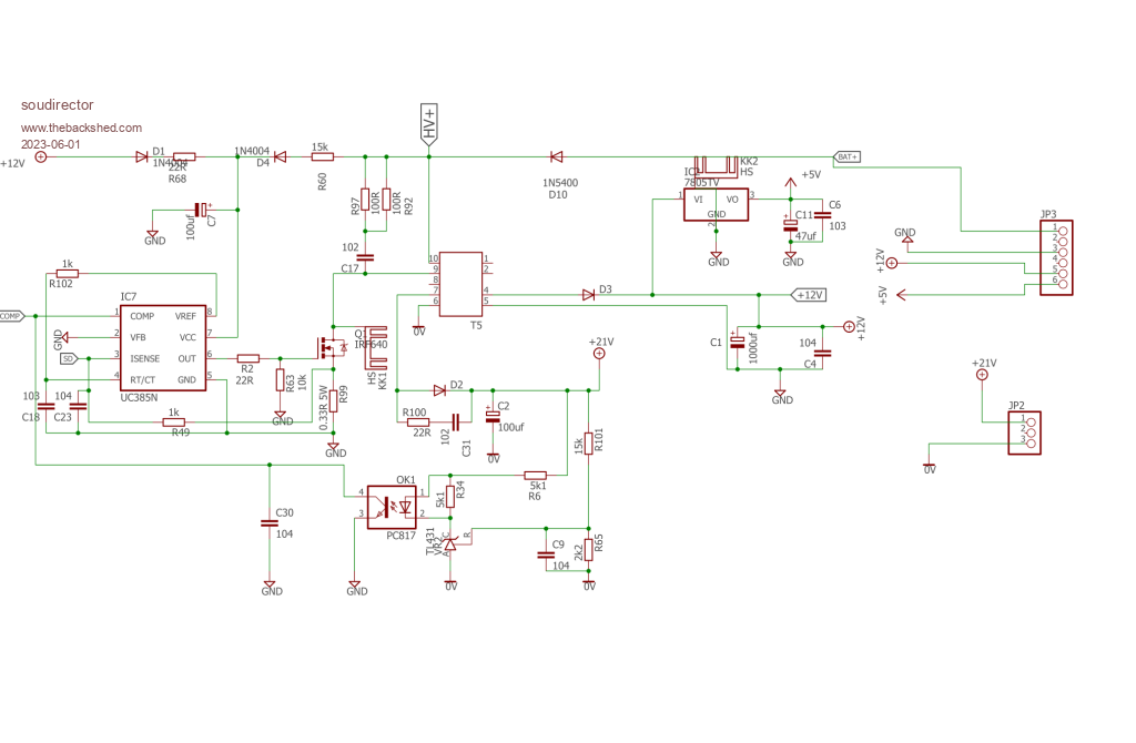

how times flies
 
Solar Mike
Guru

Joined: 08/02/2015
Location: New Zealand
Posts: 1123
Posted: 10:35am 01 Jun 2023
Copy link to clipboard 
Print this post

What is IC7, it cannot be a UC385N as that is a low drop out linear regulator, not a switching flyback type.
 
Ziki_the
Newbie

Joined: 13/04/2023
Location: Yugoslavia
Posts: 28
Posted: 10:43am 01 Jun 2023
Copy link to clipboard 
Print this post

Think it is Uc3845n.
Pozdrav iz Srbije
 
pd--
Senior Member

Joined: 11/12/2020
Location: Australia
Posts: 122
Posted: 11:34am 01 Jun 2023
Copy link to clipboard 
Print this post

https://www.ti.com/lit/gpn/uc3845

with +12v connected to the circuit do you see any output on pin 6 of IC7

how have you wound T5
 
soudirector

Newbie

Joined: 14/05/2023
Location: Nigeria
Posts: 26
Posted: 01:28pm 14 Jun 2023
Copy link to clipboard 
Print this post

  Solar Mike said  What is IC7, it cannot be a UC385N as that is a low drop out linear regulator, not a switching flyback type.


UC3845AN
how times flies
 
soudirector

Newbie

Joined: 14/05/2023
Location: Nigeria
Posts: 26
Posted: 01:28pm 14 Jun 2023
Copy link to clipboard 
Print this post

  pd-- said  https://www.ti.com/lit/gpn/uc3845

with +12v connected to the circuit do you see any output on pin 6 of IC7

how have you wound T5


NONE
how times flies
 
wiseguy

Guru

Joined: 21/06/2018
Location: Australia
Posts: 995
Posted: 10:51pm 16 Jun 2023
Copy link to clipboard 
Print this post

You have not made it very easy for anyone to help you with your post (not enough information).

As shown your circuit is not an interleaved - meaning multiple stages usually with controlled phase timing - converter.  It appears to be a flyback converter and it also appears to have a single 12V and 5V outputs that are not isolated from each other or the input voltage and it has a separate isolated 21V output.

What do you want/need it to do - what are your actual voltage and current requirements that you want at the output/s ?  What input source and voltage are you using ? What turns have you used for the transformer primary and secondaries, is it a gapped core & if so what gap ? What is the ferrite core types you are using ?

Your values for R102 and C18 are totally wrong, the data sheet says never use a resistor less than 5K, your circuit suggests 1K and with a timing capacitor of 10n the dead time is about the same as the on time period also contributing to no output at pin 6.

Use a 1n capacitor for C18 and for R102 either a 10K or 18K resistor for switching frequencies of around 200kHz (10K R102) or 100kHz (18K R102) respectively.

Your value for C23 also seems very low I typically see values from 100pF to 1nF used there.

Edit: I forgot to mention your schematic shows a +HV supply at the centre and a Batt supply on the right hand side that appears both/either could start the converter, - what is their purpose ? If the +HV could be from 12 - 48V then the value of R60 is too low for a 12V input as the resistor drops 7.5V using the datasheet startup current of 0.5mA but the chip can need up to 9V to start meaning a start minimum input of ~ 16V. A value of 10K down to 6K8 may help for 12V input.  I am assuming the +12 on the LHS is connected to the converters +12V output to supply running current once started.

Download the TI data sheet here  and try to work backwards from my suggestions and look at their typical schematic and values they used.
Edited 2023-06-17 17:22 by wiseguy
If at first you dont succeed, I suggest you avoid sky diving....
Cheers Mike
 
soudirector

Newbie

Joined: 14/05/2023
Location: Nigeria
Posts: 26
Posted: 01:32pm 08 Aug 2023
Copy link to clipboard 
Print this post

  wiseguy said  You have not made it very easy for anyone to help you with your post (not enough information).

As shown your circuit is not an interleaved - meaning multiple stages usually with controlled phase timing - converter.  It appears to be a flyback converter and it also appears to have a single 12V and 5V outputs that are not isolated from each other or the input voltage and it has a separate isolated 21V output.

What do you want/need it to do - what are your actual voltage and current requirements that you want at the output/s ?  What input source and voltage are you using ? What turns have you used for the transformer primary and secondaries, is it a gapped core & if so what gap ? What is the ferrite core types you are using ?

Your values for R102 and C18 are totally wrong, the data sheet says never use a resistor less than 5K, your circuit suggests 1K and with a timing capacitor of 10n the dead time is about the same as the on time period also contributing to no output at pin 6.

Use a 1n capacitor for C18 and for R102 either a 10K or 18K resistor for switching frequencies of around 200kHz (10K R102) or 100kHz (18K R102) respectively.

Your value for C23 also seems very low I typically see values from 100pF to 1nF used there.

Edit: I forgot to mention your schematic shows a +HV supply at the centre and a Batt supply on the right hand side that appears both/either could start the converter, - what is their purpose ? If the +HV could be from 12 - 48V then the value of R60 is too low for a 12V input as the resistor drops 7.5V using the datasheet startup current of 0.5mA but the chip can need up to 9V to start meaning a start minimum input of ~ 16V. A value of 10K down to 6K8 may help for 12V input.  I am assuming the +12 on the LHS is connected to the converters +12V output to supply running current once started.

Download the TI data sheet here  and try to work backwards from my suggestions and look at their typical schematic and values they used.


Sorry for the late reply.

Note that, this power smps is form a commercial MPPT which operate from 12v to 48v battery (auto select input voltage). Ignore the +HV and regard the BAT+ as the input source.

The primary winding depends on the voltage input range i.e 12/24v - 18t, for 36v, 48v are 28t and 38t. Secondary winding for 12v is 24t while 21v is 21t.

The dual output are 12v and 18-21v max. 21v is isolated while 12v is not. EE25 core transformer used. Air gap i don't have that information or am not sure it has.

The 5v output connected from 12v output via L7805. The D1 is connected to 12v output acting as feedback.

Regarding the components value you may be right, that maybe the reasoning why is not working.  Made it open here so that anyone can try to build it to work.
how times flies
 
soudirector

Newbie

Joined: 14/05/2023
Location: Nigeria
Posts: 26
Posted: 08:29am 21 Aug 2023
Copy link to clipboard 
Print this post

  soudirector said  
  wiseguy said  You have not made it very easy for anyone to help you with your post (not enough information).

As shown your circuit is not an interleaved - meaning multiple stages usually with controlled phase timing - converter.  It appears to be a flyback converter and it also appears to have a single 12V and 5V outputs that are not isolated from each other or the input voltage and it has a separate isolated 21V output.

What do you want/need it to do - what are your actual voltage and current requirements that you want at the output/s ?  What input source and voltage are you using ? What turns have you used for the transformer primary and secondaries, is it a gapped core & if so what gap ? What is the ferrite core types you are using ?

Your values for R102 and C18 are totally wrong, the data sheet says never use a resistor less than 5K, your circuit suggests 1K and with a timing capacitor of 10n the dead time is about the same as the on time period also contributing to no output at pin 6.

Use a 1n capacitor for C18 and for R102 either a 10K or 18K resistor for switching frequencies of around 200kHz (10K R102) or 100kHz (18K R102) respectively.

Your value for C23 also seems very low I typically see values from 100pF to 1nF used there.

Edit: I forgot to mention your schematic shows a +HV supply at the centre and a Batt supply on the right hand side that appears both/either could start the converter, - what is their purpose ? If the +HV could be from 12 - 48V then the value of R60 is too low for a 12V input as the resistor drops 7.5V using the datasheet startup current of 0.5mA but the chip can need up to 9V to start meaning a start minimum input of ~ 16V. A value of 10K down to 6K8 may help for 12V input.  I am assuming the +12 on the LHS is connected to the converters +12V output to supply running current once started.

Download the TI data sheet here  and try to work backwards from my suggestions and look at their typical schematic and values they used.


Sorry for the late reply.

Note that, this power smps is form a commercial MPPT which operate from 12v to 48v battery (auto select input voltage). Ignore the +HV and regard the BAT+ as the input source.

The primary winding depends on the voltage input range i.e 12/24v - 18t, for 36v, 48v are 28t and 38t. Secondary winding for 12v is 24t while 21v is 21t.

The dual output are 12v and 18-21v max. 21v is isolated while 12v is not. EE25 core transformer used. Air gap i don't have that information or am not sure it has.

The 5v output connected from 12v output via L7805. The D1 is connected to 12v output acting as feedback.

Regarding the components value you may be right, that maybe the reasoning why is not working.  Made it open here so that anyone can try to build it to work.


@wiseguy, i am waiting your feedback
how times flies
 
wiseguy

Guru

Joined: 21/06/2018
Location: Australia
Posts: 995
Posted: 09:16am 21 Aug 2023
Copy link to clipboard 
Print this post

I was waiting for the rest of your feedback ie

Did you try the suggested values to make it work ? what happened  when you tried ?

I already asked, What do you want/need it to do - what are your actual voltage and current requirements that you want at the output/s ? but I could not see a response from you.

What input voltage are you actually using ? What primary turns did you use for your circuit?

You said "Secondary winding for 12v is 24t while 21v is 21t." surely this is not right as they should be proportional to each other, 21V for 21T = 1V/turn but 12V for 24T = 0.5V/turn it cant be both at the same time so there are issues with the information provided.

I think the next progress would be first to try the component changes I suggested and report back with the results and the other information - I am not guaranteeing I will be able to help further but there others here who might also be able to contribute.
If at first you dont succeed, I suggest you avoid sky diving....
Cheers Mike
 
soudirector

Newbie

Joined: 14/05/2023
Location: Nigeria
Posts: 26
Posted: 10:47am 21 Aug 2023
Copy link to clipboard 
Print this post

  wiseguy said  I was waiting for the rest of your feedback ie

Did you try the suggested values to make it work ? what happened  when you tried ?

I already asked, What do you want/need it to do - what are your actual voltage and current requirements that you want at the output/s ? but I could not see a response from you.

What input voltage are you actually using ? What primary turns did you use for your circuit?

You said "Secondary winding for 12v is 24t while 21v is 21t." surely this is not right as they should be proportional to each other, 21V for 21T = 1V/turn but 12V for 24T = 0.5V/turn it cant be both at the same time so there are issues with the information provided.

I think the next progress would be first to try the component changes I suggested and report back with the results and the other information - I am not guaranteeing I will be able to help further but there others here who might also be able to contribute.


Honestly, i don't know other details apart from what i already told you. All i need is a working smps circuit that will handle 24vdc-48vdc inputs, Outputs isolated 18-21vdc and non-isolated 12.5vdc.

I don't know how the wind the coils. i got the schematic from a blog site and it appears is what i am looking for but information is limited.

Anyone that has knowledge should help.
how times flies
 
Print this page


To reply to this topic, you need to log in.

© JAQ Software 2024