
|
|
Forum Index : Electronics : Inverter standby power
| Page 1 of 2 |
|||||
| Author | Message | ||||
| Murphy's friend Guru Joined: 04/10/2019 Location: AustraliaPosts: 678 |
Living off grid it's important for the inverter to draw as little as possible power from the batteries when it's just idling. This post is about the inverter I started building back in 2016, see topic This inverter has given me lots of grief (painful learning curve) initially until I got it running. But there were still unexplained failures so I had a few re builds by now, the latest running with Poida's NANO control. Anyway, the remarkably low idle power figures KeepIS posted about from his built (similar power size than mine) prompted me to check the idle power again. I was in for a shock. Back when that 6KW inverter first ran, idle power was measured at 29W. Later on, after some modifications it was 44W. But now I measure 120W! I seem to have progressed backwards. What caused this? No idea. Trying to improve things I started with that monster transformer, back then when I wound it I did not know about going for 1 Tesla flux density. So, off came that 90mm sq primary, having been epoxied on it was only good for scrap. I added 46 turns to the secondary to bring the flux density down from 1.4 Tesla to 1.0 Tesla. A new primary was wound from 25mm sq welding cable (outer sheath removed). The secondary was tuned to precisely 75Hz with a capacitor, as the original was way out due back then not having a good signal generator. So, with the transformer being as good as I can make it, the idle power reduced to 103W. What else can I change? The original control board ran a EG8010 chip, the latest has a NANO with Poida's latest program. What If I swap just the control boards, leaving the rest of the inverter and the voltage settings identical for this test? So, Nano board, AC=230V, DC = 54.6V, power = 103W EG8010 board, AC=230V, DC = 54.6V, power =120W Well done Poida, your program beats the EG8010 by 17W in my inverter. But I'm still guessing where else the extra idle power has gone, anybody has ideas? I did experiment with different chokes (I have a good selection), some did improve the sine wave but none did much to lower the idle power. I tried to post pictures here but the upload is soo slow the server times out... |
||||
Revlac Guru Joined: 31/12/2016 Location: AustraliaPosts: 1282 |
I remember that thread, It was the one that inspired my first proper inverter build.  It seems a bit strange to have gained so much in losses, Have you tested just the transformer running from a 230vac supply? should be 7-15 watts or something if its working properly. only other thing would would be a bad component somewhere, would expect some heat with that high wattage. Cheers Aaron Off The Grid |
||||
| KeepIS Guru Joined: 13/10/2014 Location: AustraliaPosts: 2196 |
Hi Klaus, I've just finished fitting the newer control board designed by wiseguy, I had a wish list of larger sockets and other additions which he managed to fit on the new board. My idle current is 30.5 Watts, that included a low speed fan running, a big auto start Solenoid engaged, and a number of Leds and gauges, you will recall that his design is running his Modulation scheme, I think implemented by Poida in the Nano? please correct me if I'm wrong So something is going on there as that's 3 to 4 times more then my Inverter? I'm in the middle of doing a Reno on the bathroom so there is little time for the forum for the next couple of weeks, hopefully you can get it back to what you once had . NANO:Inverter V 8.2ks - Linux AvrDude GUI script V4.1 |
||||
renewableMark Guru Joined: 09/12/2017 Location: AustraliaPosts: 1679 |
Maybe try and disconnect the secondary windings and see if one is faulty? Also try a infra red thermometer gun to check if any bits are getting hot? I had some sh*t tip 35's from memory that f'kd things up. Edited 2023-08-09 20:33 by renewableMark Cheers Caveman Mark Off grid eastern Melb |
||||
| Murphy's friend Guru Joined: 04/10/2019 Location: AustraliaPosts: 678 |
Thanks Mark, when I added turns to the secondary (there were 4 parallel windings of 100 turns each originally) I wound 46 x4 extra turns on. Then I measured the voltages individually, powering one winding from 230V. They were all within 0.2V so no transformer problems. It does not get warm either. What does get warm are the heatsinks, checked with my infrared sensor and none of the 16 Hy4008's is unusually hot. I do not use the Tip type transistors for the totem pole, instead using much better transistors that wiseguy recommended. It's such a simple opto isolated driver/ power arrangement, hard to see why it gobbles power at idle. The control board by itself used only a few watts at most. I'll do some more testing, there is plenty of time for that since I have the warpverter powering the house now. |
||||
| Murphy's friend Guru Joined: 04/10/2019 Location: AustraliaPosts: 678 |
Thanks Aaron, the transformer on its own, powering the secondary from 230V AC, consumes 11 watts. I'm very pleased with that, worth the effort of adding turns. |
||||
| Murphy's friend Guru Joined: 04/10/2019 Location: AustraliaPosts: 678 |
Thanks Mike, The EG8010 control board was made to wiseguy's schematic, minus the fancy shut off components. It runs well, nice AC sine wave but 120W idle. The other control board uses the NANO with Poida's program, 103w idle. Also runs well with a nice sine wave AC. 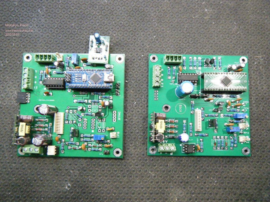 Easy to swap boards. |
||||
| mab1 Senior Member Joined: 10/02/2015 Location: United KingdomPosts: 282 |
Have you checked your series inductor is ok? No shorted turns? Could explain the heatsinks running 'hot' if it's not doing its job. |
||||
| Murphy's friend Guru Joined: 04/10/2019 Location: AustraliaPosts: 678 |
Yes I have, thanks. There is quite a selection of chokes here, none improved standby power by much but does affect the sine trace. 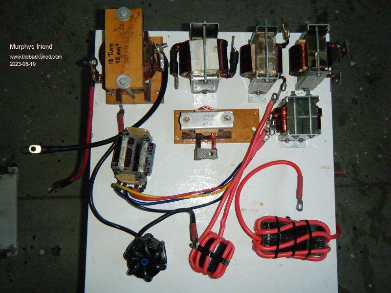 |
||||
| tinyt Guru Joined: 12/11/2017 Location: United StatesPosts: 561 |
I don't know what power board you have. It is possible that there are leaky power mosfets, totem pole drivers, etc. Maybe swap out totem pole drivers first which I think is easier to do. Maybe if you disconnect the transformer, you can ohm out which section of the mosfet H bridge is leaky, and/or remove mosfet high/low pairs one at a time until you have only one mosfet per leg of the bridge. And if idle is still high, the leaky one(s) could be one or more of the mosfets still connected. Edited 2023-08-10 02:48 by tinyt |
||||
| renewableMark Guru Joined: 09/12/2017 Location: AustraliaPosts: 1679 |
Bad cap on the power board? Something has obviously degraded, you might have to just start substituting parts till you sort it out. Have you got a spare power board? Cheers Caveman Mark Off grid eastern Melb |
||||
| wiseguy Guru Joined: 21/06/2018 Location: AustraliaPosts: 1297 |
Check the driver board and especially the buffer transistors are all installed correctly and not faulty. Don’t just swap out another board or boards a build fault could have been copied. It sounds a bit like slow switching of the Mosfets which a faulty buffer section could cause, TinyT was eluding to this too. What gate resistors & Mosfets are in that build? What value of AC cap was required for resonance @ 75Hz? Edited 2023-08-10 08:24 by wiseguy If at first you dont succeed, I suggest you avoid sky diving.... Cheers Mike |
||||
| Murphy's friend Guru Joined: 04/10/2019 Location: AustraliaPosts: 678 |
Thanks guys, your suggestions are very much appreciated. I'll answer wiseguy's last question first: 3.3uF For the other questions pictures & schematics may be better than words, some of you may know that I build my inverters different to common all on one PCB layouts. 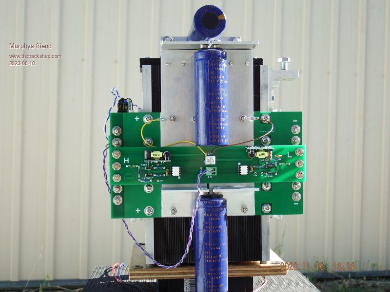 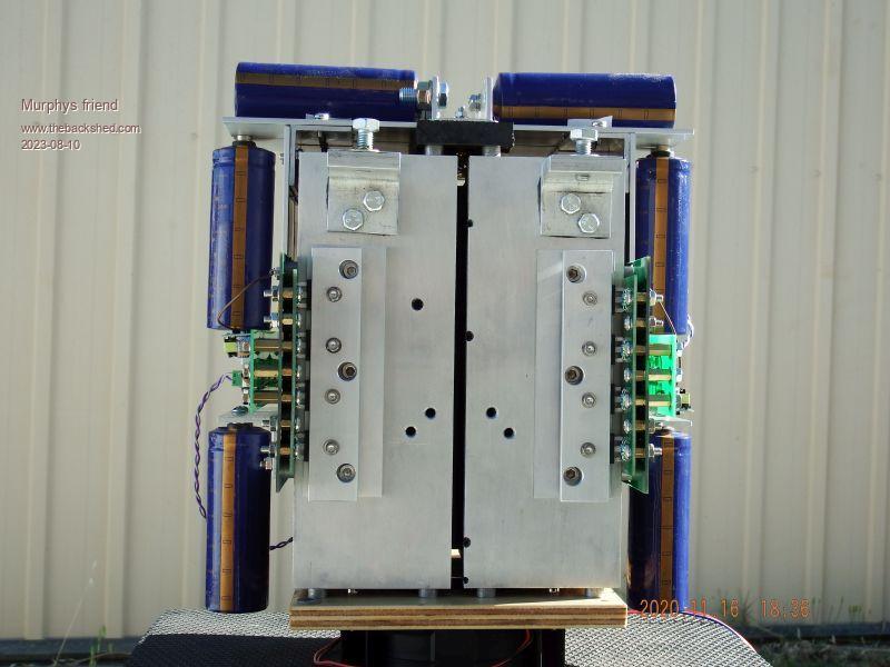 The above boards are situated around the heatsink corner from each other. The power board shows the mosfets (under the clamping bars) for 1/2 drive, the other 1/2 is opposite on the heat sink. The driver/ power schematic:  |
||||
| renewableMark Guru Joined: 09/12/2017 Location: AustraliaPosts: 1679 |
When you build one of these you go though a few steps to check if each step is performing well yeah? So maybe just go back through that. The way you built it it's clearly VERY easy to pull apart and re assemble. You know the drill. You'll find it. Might be just something loose in there causing resistance. Cheers Caveman Mark Off grid eastern Melb |
||||
| Murphy's friend Guru Joined: 04/10/2019 Location: AustraliaPosts: 678 |
Yes Mark, I learned long ago to make it VERY easy to get to all parts in my inverters  . .The annoying (or fortunate?) thing is the inverter runs perfectly well, no smoke and the heatsinks/ mosfets all measure around 35 degrees on this 18 degree winter day after being on for 4 hours, no load. |
||||
| tinyt Guru Joined: 12/11/2017 Location: United StatesPosts: 561 |
I think that 17 degrees heatsink temperature rise is the 103 watts being dissipated. With no load and low idle power, I would expect the heatsink/mosfets temperature after four hours to be just slightly higher than ambient. Assuming all 2R2 and 10K gate resistors are good, try disconnecting the four 1R mosfet drive resistors. Re-measure idle power, if it is still high, my guess is either leaky mosfet(s) or leaky bulk capacitor(s). If idle power became lower, the problem could be in the drive circuits. Edited 2023-08-11 00:34 by tinyt |
||||
| nickskethisniks Guru Joined: 17/10/2017 Location: BelgiumPosts: 481 |
I would check every voltage/power rail/level with a scope. Make sure you check those deadtime capacitors, they can go faulty. |
||||
| poida Guru Joined: 02/02/2017 Location: AustraliaPosts: 1480 |
I would suspect poor dead time in Gate drives. While proving that there is the correct timing, I would also verify correct Gate drive voltages. If above is perfect, then you have shown it's not the choke, nor the resonant frequency (testing all those chokes would have tested all the different freqs too) and the toroid does not suddenly develop 10x losses. Do you have a spare toroid, no matter what size, that you can compare with? They DO retain some magnetism in their core, even if we are told they should not or do not. This can effect output waveform shape quality Next look at signal integrity 5V PWM verses opto output, verses Gate voltage and pay attention to signal quality and delays. This will also verify correct operation of the isolated supplies. Maybe a transistor in the totem pole is not quite good and this will show it. Edited 2023-08-11 09:12 by poida wronger than a phone book full of wrong phone numbers |
||||
| Murphy's friend Guru Joined: 04/10/2019 Location: AustraliaPosts: 678 |
Thanks guys, I really appreciate all your suggestions. A little update from today; I powered it up without the primary connected and the standby power dropped to 85W. I then tested all the resistors on the drive board & mosfet carrier, all correct value. Then the totem pole transistors, had to unsolder them to test properly, all tested fine, each has plenty of gain. Testing was with this neat gadget, the trace shown is from the common gates of the totem pole to ground at the LO side drivers. The HI side trace is similar but below the base line. 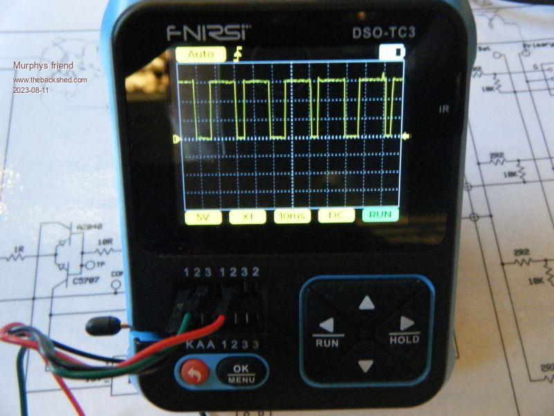 Next job is to make 4 mosfet carrier boards (visible in a photo above) but only one HY4008 on each. That would eliminate a fault with the 16 now in use. After that, don't know. I neither have the knowledge or the equipment to check dead times etc. |
||||
| Solar Mike Guru Joined: 08/02/2015 Location: New ZealandPosts: 1228 |
Those Fod3182 opto drivers can have a lot of variation in spec between chips, if they are in sockets and you have some spares, swap them out and test again without the primary connected, high currents with no primary connected looks like possibly too small a dead time with partial shoot through between HO\LO. |
||||
| Page 1 of 2 |
|||||
| The Back Shed's forum code is written, and hosted, in Australia. | © JAQ Software 2026 |
