
|
|
Forum Index : Electronics : Inverter standby power
| Author | Message | ||||
| poida Guru Joined: 02/02/2017 Location: AustraliaPosts: 1432 |
now I am certain it's shoot through. This is when both high and low side FETs are ON at the same time. To prove this, look at FET gate drive for low and high side for each of the two 1/2 bridges. Look at the timing. Prove that when low side Gate is ON, high side is already OFF and vice versa. For both 1/2 bridges (i.e. low and high side pairs) Note well that the high side gate drive will be riding on top of DC+, so it is a signal relative to that. This means you can never connect the low side Source to the high side Source in an attempt to get a "ground" for the DSO signals. wronger than a phone book full of wrong phone numbers |
||||
| wiseguy Guru Joined: 21/06/2018 Location: AustraliaPosts: 1206 |
With the toroid transformer high current primary disconnected, remove one of the opto drive wires from one side of the half bridge and now check the input power. Then reconnect the wire and do the same input power check to the opposite half bridge (disconnect one of its opto drive wires first). What are the input powers for each half? Maybe a divide and conquer approach may help isolate the issue to one half bridge side ? Edited 2023-08-12 16:54 by wiseguy If at first you dont succeed, I suggest you avoid sky diving.... Cheers Mike |
||||
| Murphy's friend Guru Joined: 04/10/2019 Location: AustraliaPosts: 671 |
Thanks again guy's, more good suggestions. But I think Solarmike (and Poida) is on the money with the dead time. Today I replaced the dead time capacitors for the next size up, even selected two that measured very closely the same value. The DC power (no transformer) reduced to 50W. So, tomorrow its more capacitor changes (I fitted matrix pins on the PCB to make that easier) to get to the lowest DC power. I'll keep you posted how this goes. |
||||
| wiseguy Guru Joined: 21/06/2018 Location: AustraliaPosts: 1206 |
What value of deadtime capacitor was originally installed and what value did you measure for the ones you removed? If they became smaller in value then maybe I could agree, however you have installed a larger value and still have around 50W of idling power where as with no output transformer the H bridge stages power should be maybe 1 or 2W maximum. It sounds more like you are treating symptoms rather than curing the fault. When you get to the threshold point of deadtime it is more like falling off a cliff, the power does not usually go from 100W to 50W it goes down to 1 or 2W. The fact your Mosfets are still alive tells me that the original conduction point between upper Fets turning off and and lower Fets turning on or vice versa where some unintended conduction is happening is marginal and not serious, the change to larger deadtime capacitors should have cured the issue in my opinion. Lastly unless you have recently replaced the Mosfet types or gate resistors their deadtime does not change with time, their switching time might have degraded due to other reasons though. I still think removing the opto drive from each half of the inverter as previously suggested might be revealing. In theory they should be 25W each or one side might be closer to 50W? Out of curiosity has there ever been a FET blow up with those driver boards? Are the heatsinks still warm with the increased deadtime caps - ie, is your power meter lying to you ? Edited 2023-08-13 07:37 by wiseguy If at first you dont succeed, I suggest you avoid sky diving.... Cheers Mike |
||||
| tinyt Guru Joined: 12/11/2017 Location: United StatesPosts: 441 |
For comparison: My re-wound 5kva toroid transformer idle power measures 11.5 VAR. When I assembled it with a 24-mosfet 48V chinese inverter board, the idle power is 18.2 watts using chinese toroid chokes (I did not use the on board 12V stepdown transformer and 5uF 'tuning' capacitor). When I replaced the chinese chokes with a DIY one, the idle power became 17 watts. So, the chinese inverter board (EGS002 and totem-pole bipolar transistor drivers) has an idle power of roughly 6 watts. Edited 2023-08-13 13:14 by tinyt |
||||
| Murphy's friend Guru Joined: 04/10/2019 Location: AustraliaPosts: 671 |
More suggestions, thank you. I stuck to the dead time capacitor value tip and followed that. Here are the results: BTW, these are measured cap values, in each case the printed value was higher. I used greencaps. All no transformer: 1.85nF = 85W 2.41nF = 50W 2.96nF = 40W 3.58nF = 33W 4.30nF = 27W I left the last one in place and connected the transformer, idle power jumped to 27.2W I'm happy with that, its better than the 29W that inverter had in its first incarnation 7 years ago. The inverter is now powering my house, let's see how that goes. Here is a pic of the driver board, the dead time cap is next t5o the 'IN' connector. 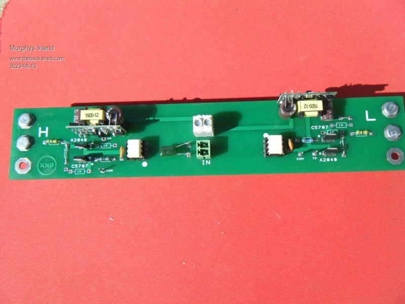 I did extensive tests of my chokes (more of that in another post) and decided to use the powdered iron ring cores for their gentle 'knee' curve. They have the added benefit of silence due no air gap buzz. There is a choke in each of the primary legs. The red one has 8 'rings', 9 turns of 20mm sq cable and measures 100uH on my LC tester. The saturation 'knee' is around 150A. 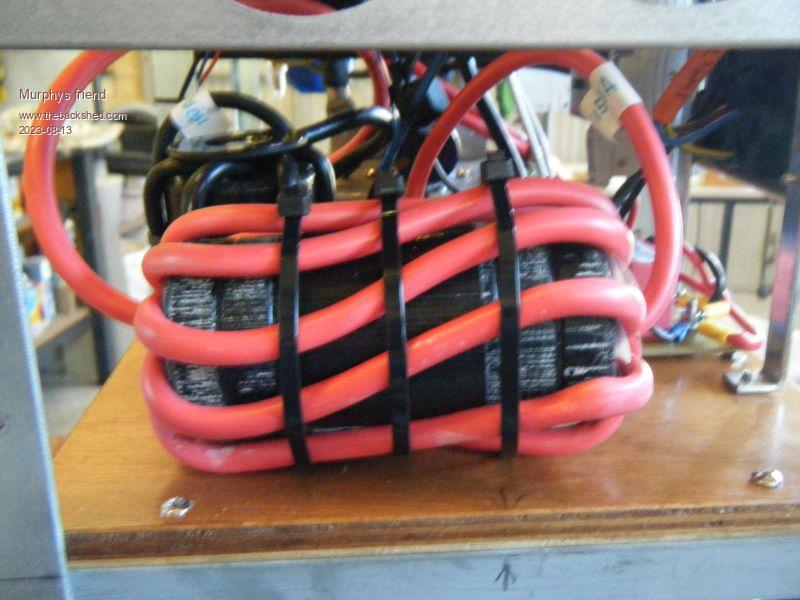 The black choke has two CS610125 'rings', 7 turns of 20 mm sq cable and measures 62uH on my LC tester. This one also has the 'knee' at 150A. Here is a picture of the idle sine trace: 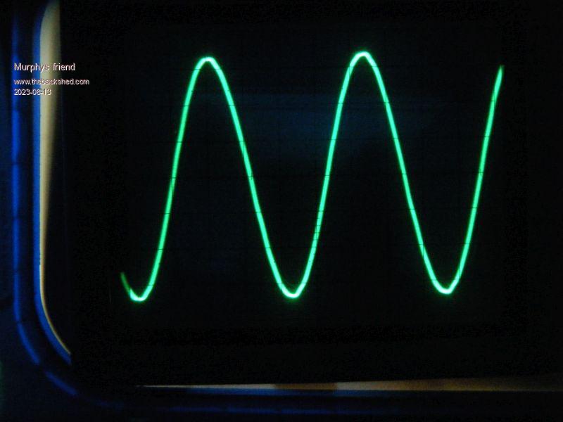 Once the inverter was powering my house with the reverse cycle A/C running, fridge loads, bar heaters & kettle, totaling close to 5KW there was no obvious change in the sine trace. Running the induction cooktop (1800W) or the microwave (1000W) a small trace change: 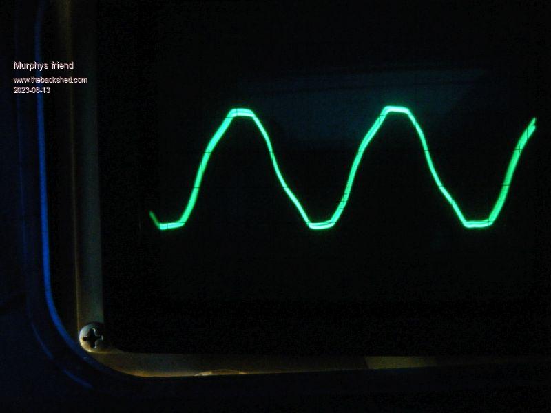 So, what caused the idle power increase? Most likely myself  . I cannot resist tinkering with this thing and every time I see a post with a 'good' idea I have to try that. . I cannot resist tinkering with this thing and every time I see a post with a 'good' idea I have to try that.So, since the start there have been 3-4 complete re builds, initially because of blow up problems. The one before last version had been running well, powering the house when I messed about with an extra GTI backfeeding and something went wrong, blowing a half bridge worth of mosfets. Anyway, its going now, perhaps not at absolutely minimal idle current but better than what KeepIS postes with his build  . .I'll eave some of the not tried suggestions for next time I take the covers off this inverter. Thank you all for your input, a great team effort, solving the puzzle which put me back to a useful inverter. |
||||
| wiseguy Guru Joined: 21/06/2018 Location: AustraliaPosts: 1206 |
My inverter half bridge drive uses 2 x 120R resistors from the HC86 driver and a 1n capacitor. The time constant is ~240nS, the power with no transformer is ~ 1W, idling power with transformer is ~ 18W. The time constant deadtime capacitor made no difference to the half bridge power drawn once the deadtime exceeded 180nS. But reducing its value past a certain point ( from memory ~ 120nS ) started to rapidly increase current. I would be very curious about requiring a deadtime capacitor nearly 8 times larger than the minimum deadtime usually required and a current consumption still around 25 times higher than what I would call normal, but I accept I am a bit fussy. Maybe it may help to think about the name "dead time". Qnce its dead you should not be able to kill it further and further and still only have it half dead ? My table looked like this; 470pF = 5W 560pF = 2W 680pF = 1.3W 1n0 = 1.1W 1n5 = 1.1W Edited 2023-08-13 22:06 by wiseguy If at first you dont succeed, I suggest you avoid sky diving.... Cheers Mike |
||||
| Murphy's friend Guru Joined: 04/10/2019 Location: AustraliaPosts: 671 |
Well Mike, being "fussy" is, I thought, a mandatory requirement of an electronic engineer  . .But I agree, were not quite yet at the bottom of this topic. You say that your inverter's idling power with transformer is 18W and I assume its a 6KW inverter. So when my 6KW inverter has 27W idling power, that does not sound too bad to me. Anyway, I'm thinking of getting a 2 channel digital scope so I can see that mysterious "dead time" for myself - hopefully not blowing mosfets in the process. Fortunately there are two smaller inverters (home built) sitting around here as spares so I can tinker with them and not robbing the power source for my house. |
||||
| tinyt Guru Joined: 12/11/2017 Location: United StatesPosts: 441 |
I used chinese advertised 'ferro-silicon aluminum toroid' which is probably similar to what you used. Also 8 rings, 9 turns 70 strands AWG #19 (0.653 mm2 cross section x 70 = 45.7 mm2 equiv. cross section). According to a data sheet, AWG #19 max frequency for 100% skin depth is 21kHz. 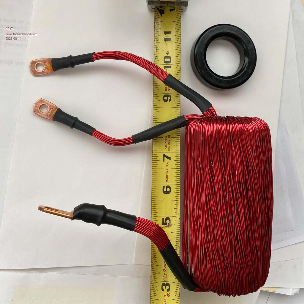 Here is saturation curve: 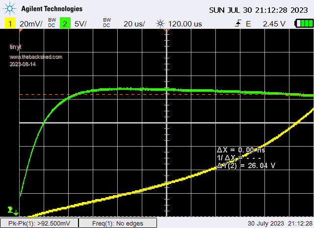 The 'scope I used for saturation testing can save the readings as spreadsheet data. Using it, the following are calculated average inductances at various current ranges: 20A - 80A: 45 uH 80A - 120A: 40 uH 120A - 160A: 35 uH 160A - 200A: 30 uH 200A - 240A: 27 uH I only used one choke at the 23KHz mosfet bridge leg, none at the 60Hz mosfet bridge leg. Edited 2023-08-14 02:30 by tinyt |
||||
| wiseguy Guru Joined: 21/06/2018 Location: AustraliaPosts: 1206 |
I was guessing there had been a blowup, I would further guess that the repaired pcb is probably the culprit. I remember chasing a half bridge fault where all the components measured fine but it refused to work properly. The fault was on a flow through joint that didn’t, It was open circuit on the topside between the hole ferrule and the donut pad. Soldering the FET leg from the topside restored operation. The easiest test is to simply open circuit the transformer connection and remove the opto drive from each half bridge side in turn and check the idle power result. Hopefully it will lead you to which half needs “ work”. I applaud your CRO aspirations as waveform comparisons between a working circuit and non working circuit can be a great help. The small dc/dc converters probably use cheap capacitors, usually the output capacitor ~ 330 - 470uF is the first to dry out & may be suspect easily tested with a temporary cap placed across the suspect one noting polarity & voltage. You will find the reason don’t give up! If at first you dont succeed, I suggest you avoid sky diving.... Cheers Mike |
||||
| Murphy's friend Guru Joined: 04/10/2019 Location: AustraliaPosts: 671 |
Mike, have another look at the way I have the mosfets mounted (picture on page 1). You'll see they are on little carrier boards, 4 mosfets per board. If there 'is' a blowup I just replace the whole carrier board & new parts on it, no thru hole problems then. Also, this inverter 'is' working fine now, are you sure there 'is' still a fault? Maybe the higher than your dead time capacitance has something to do with my board layout, I really have no idea. Today I took the covers off my 3KW inverter (identical electronics, just smaller toroid) and it appears there is the same dead time capacitance issue. I'll tackle that tomorrow. |
||||
| Murphy's friend Guru Joined: 04/10/2019 Location: AustraliaPosts: 671 |
tinyt, I applaud your patience with paralleling 70 strands of fine wire to make suitable cross section. The re cycled toroid rings I used did have an original winding of that style but nowhere near 70 strands, just 4 thicker wires I remember. I think your method would be the preferred one but mine is quicker .Could you tell me the formulae you used to get the inductance from the data points you quoted? Its been too long since I had a need for that calculation and have forgotten how. |
||||
| tinyt Guru Joined: 12/11/2017 Location: United StatesPosts: 441 |
I tried using ready made chinese toroid chokes but decided I can not avoid making my own to meet my desired inductance. The rings were harvested from these chokes which measured low inductance during saturation testing even with 3 in series. 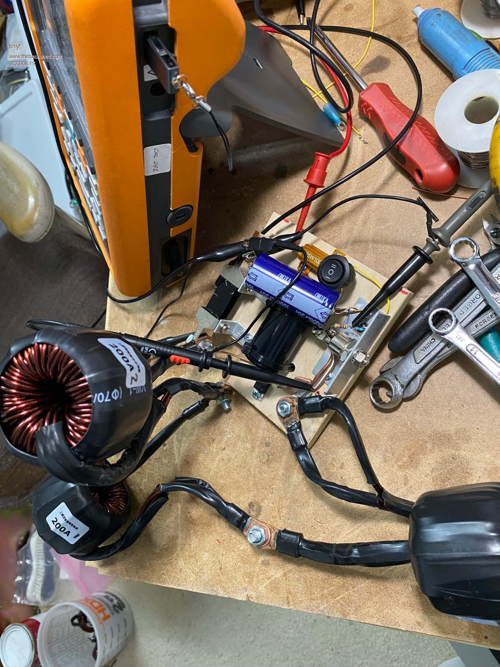 Attached zip file has the spreadsheets in .ods and xlsx formats. First few readings are not useable because of 'noise'. Look at the column headings and formulas in cells column I, rows: 314,612,826,982,1098,1190 then work back. I hope they are correct. (ignore content of cells columns J-L, rows 7-28). DIY choke scope capture.zip Edited 2023-08-15 02:41 by tinyt |
||||
| wiseguy Guru Joined: 21/06/2018 Location: AustraliaPosts: 1206 |
Klaus I seem to be the odd one out thinking you should do more and in my belief that there is something still not right. The discussion started with you rolling up your sleeves to get to the bottom of high idling power, my "help" was to try to assist with that. I will wave a white flag and withdraw from further "help" here. If you are happy with the results and it appears to be working albeit with warm heatsinks please continue. If at first you dont succeed, I suggest you avoid sky diving.... Cheers Mike |
||||
| phil99 Guru Joined: 11/02/2018 Location: AustraliaPosts: 2578 |
Yes, even in my limited experience something is not quite right. If the only issue were too little deadtime increasing the capacitor should have cured it entirely at a well defined point. Perhaps the underlying issue is unusually slow turn-off of one or more MOSFETS. That would explain why it gets progressively better as you increase the capacitor size and why you end up with such a large value. |
||||
| wiseguy Guru Joined: 21/06/2018 Location: AustraliaPosts: 1206 |
I concur with your summary of the deadtime capacitor effect & also believe there is a slow turn off most probably on the lower FETs I would be looking at the buffer stage especially the PNP or the lower buffer power supply but I just feel like I am swimming against the tide and I tire more easily these days. Edited 2023-08-15 09:00 by wiseguy If at first you dont succeed, I suggest you avoid sky diving.... Cheers Mike |
||||
| Solar Mike Guru Joined: 08/02/2015 Location: New ZealandPosts: 1162 |
Looking at your driver module and you may have done this already, I would remove the two 1R resistors driving each set of mosfets, plus provide some current spike isolation for the two 15V psu's; see drawing below. Note C2,3 should be very low esr type, I use solid electrolytic caps here as their esr is in the 10s of mR. 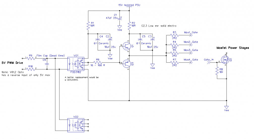 Cheers Mike |
||||
| phil99 Guru Joined: 11/02/2018 Location: AustraliaPosts: 2578 |
One simple way to test for slow turn-off would be a 1k between C and E of Q3 or G and S of one of the FETs, if that is easier. If that is the problem it should reduce dissipation a little further, or allow a smaller dead-time capacitor. If slow turn-off is due to a faulty FET this won't make any difference. |
||||
| tinyt Guru Joined: 12/11/2017 Location: United StatesPosts: 441 |
If it is easy to swap the HO mosfet leg assembly with the LO mosfet leg assembly and the idle current changed, then there is a high probability that the problem is with the mosfets. Just guessing. |
||||
| Murphy's friend Guru Joined: 04/10/2019 Location: AustraliaPosts: 671 |
Thanks Mike, your input is always very much appreciated, however, I do not yet have the equipment to electronically go any further. Besides, I'm not sure the heat sinks still get warm at idle, did not let it idle long enough after the last capacitor change, so this is just a guess at this stage. Anyway, as I have another (spare) inverter to play with I'll try all the swap suggestions mentioned as this inverter also has more idle power than its original incarnation had. I think it has something to do when I rebuilt these inverters to run with the NANO program, using the opto isolated drivers. I will also try solar mike's suggestion as those driver boards are presently on my bench waiting for a capacitor swap. |
||||
| The Back Shed's forum code is written, and hosted, in Australia. | © JAQ Software 2025 |
