| Author |
Message |
mab1
Senior Member

Joined: 10/02/2015
Location: United KingdomPosts: 282 |
| Posted: 05:52pm 22 Aug 2023 |
 Copy link to clipboard Copy link to clipboard |
 Print this post |
|
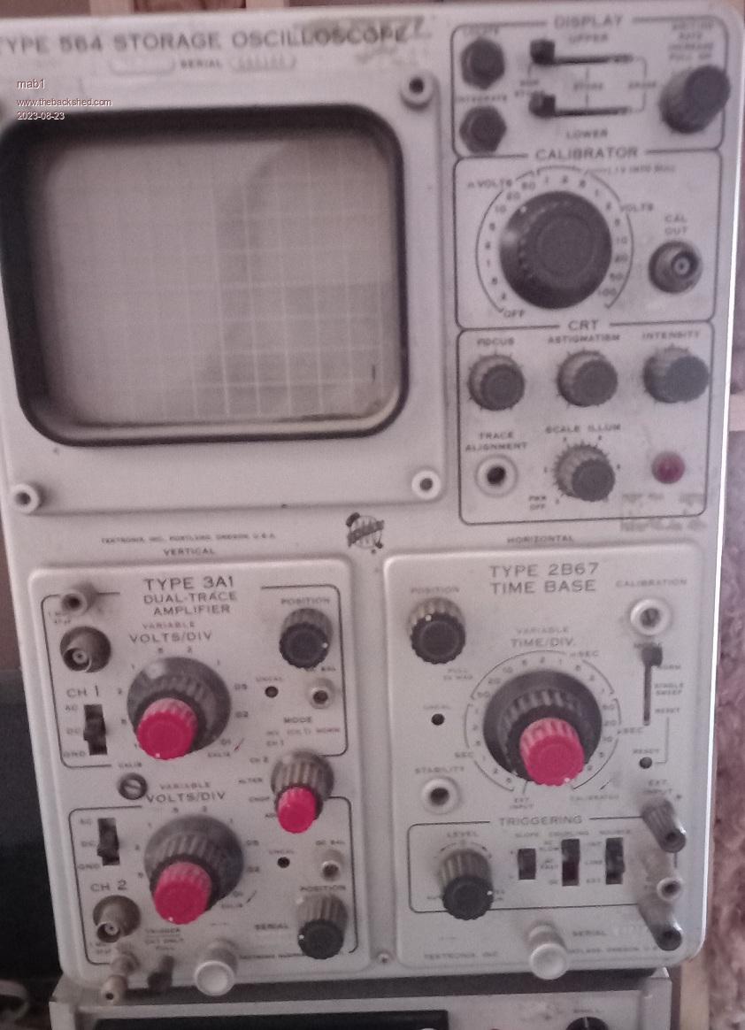
I have an old tektronix 564 storage oscilloscope, and the timebase plugin has stopped oscillating. This is the description of the fault -sorry if it's a bit long winded:-
last time it was working, it wasn't triggering on 'auto' and over the course of an hour the trigger level kept having to be turned up until it reached the end of its travel and wouldn't trigger at all, nor run on 'free run'. No amount of fiddling with the controls now will get it to sweep.
If set to ext X input the dot appears, the horizontal position knob works as expected and is not far off midposition to center the dot, and a signal on the x input deflects the dot as expected, but switch back to time/div and the dot dissapears (to the left i think).
The only other clue is that the timebase has a single sweep switch, which when set to single sweep and reset would normally light the 'ready' indicator ' this dors not light up.
Usually when this scope goes belly up it's either a resistor or a 'blown'(air got in) valve, but i think I've tested every resistor, the power supply rails to the plugin (-100, -12.2, 125 and 300v regulated - i don't think this plugin uses the unregulated supplies), and all the valves are glowing so the 6.3v is there.
I do have the manual with the schematics, but the test conditions shows waveforms with the timebase free-running which it isn't, and more of an issue is that the valve bases and the passive components are on the 'inside' when plugged into the mainframe which severely limits access to test points.
 |
| |
mab1
Senior Member
Joined: 10/02/2015
Location: United KingdomPosts: 282 |
| Posted: 06:03pm 22 Aug 2023 |
Copy link to clipboard |
Print this post |
|
Sorry that wasn't a very good pic.
Here are 3 schematics
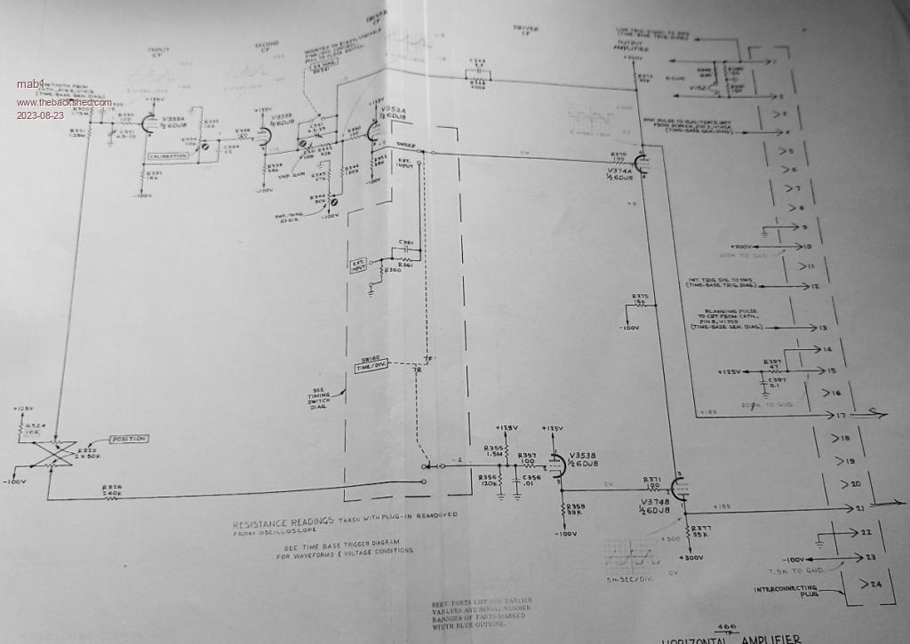
Output amp - I'm thinking this oart is working normally:
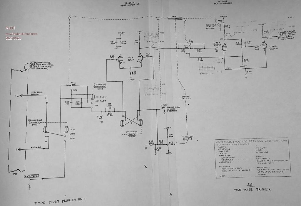
Trigger:
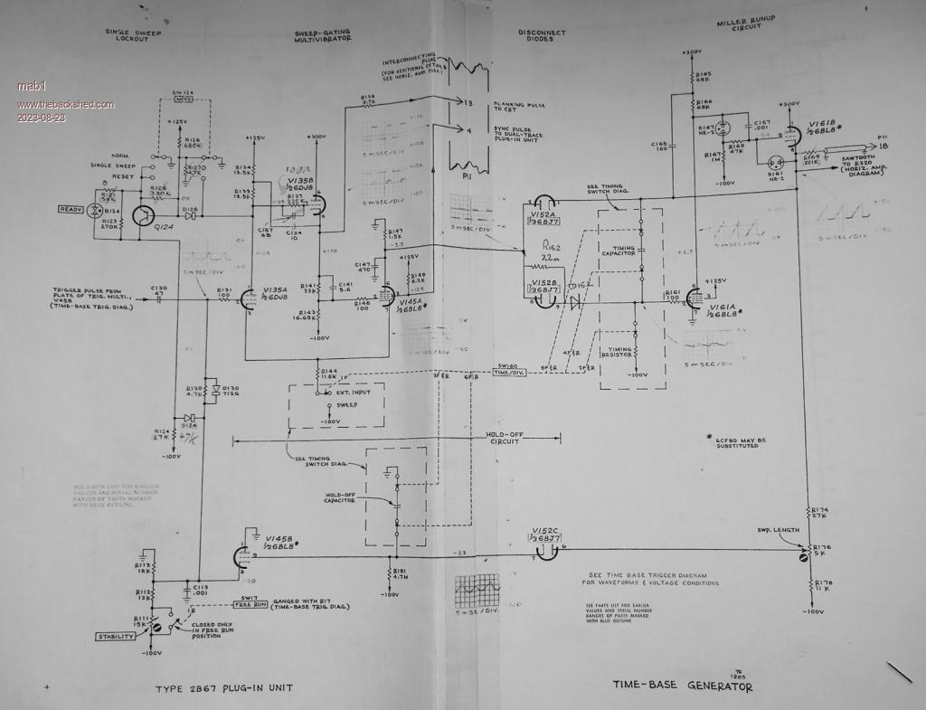
Timebase:
Hopefully i haven't made them unreadable by downsizing.
I'm thinking that the trigger circuit should oscillate to drive the timebase?
But I'm not sure, hence i would appreciate any guidance on identifying the problem. Otherwise the only thing i can think of is to randomly swap valves around on the assumption one of them is faulty.
Edited 2023-08-23 04:23 by mab1 |
| |
oh3gdo
Regular Member

Joined: 18/11/2021
Location: FinlandPosts: 47 |
| Posted: 06:54pm 22 Aug 2023 |
Copy link to clipboard |
Print this post |
|
Mab1
Very interesting device.
I have been two years in Rhode & Schwarz, Munich in 1970 and 1971 repairing Tektronix oscilloscopes.
The schematic is almost difficult to read, but check first that voltage levels go to first two tubes, like -10 to +10V.
Measure the cathode of the second tube.
How it changes?
Then is the most interesting two tubes.
They are used as an oscillator (which is not working).
Look that the DC level goes to first of the second tubes.
Then measure the anode voltage from the second tube.
How much is it?
And then use external capacitor, the same size than it should be and touch the old capacitor to the both ends.
It should start to oscillate.
If not, measure the backup capacitor and the parallel resistor.
This is my first advice .
Regards Pekka Ritamaki Finland. |
| |
mab1
Senior Member
Joined: 10/02/2015
Location: United KingdomPosts: 282 |
| Posted: 07:42pm 22 Aug 2023 |
Copy link to clipboard |
Print this post |
|
Hi pekka, thanks for your reply.
Just to be clear:- by the first two valves do you mean V24 A and B (trigger amp)? And 2nd two V45 A and B (trigger multivibrator)?
Do you know if it is acceptable to put the timebase plugin in to the left side (Y amp) side of the chassis?
That's the only way i can see to access the valve bases and associated components to measure voltages. |
| |
wiseguy

Guru

Joined: 21/06/2018
Location: AustraliaPosts: 1297 |
| Posted: 01:02am 23 Aug 2023 |
Copy link to clipboard |
Print this post |
|
Maybe a silly question but have you tried contact cleaner (servicesol?) in that multi gang timer switch and operating it immediately after spraying. The rest you probably need a CRO to see what is happening 
If at first you dont succeed, I suggest you avoid sky diving....
Cheers Mike |
| |
mab1
Senior Member
Joined: 10/02/2015
Location: United KingdomPosts: 282 |
| Posted: 01:18am 23 Aug 2023 |
Copy link to clipboard |
Print this post |
|
Not a silly question at all - but i have used contact cleaner on the switches, including the time/div switch.
I do have another (working) cro - telequipment s43, but the issue is getting access to the valve contacts of the timebase when the timebase plug-in is in the chassis - hence my wondering if i could plug it in on the other (y amp) side. Well, that and my limited understanding of how it works. :) |
| |
Godoh
Guru
Joined: 26/09/2020
Location: AustraliaPosts: 675 |
| Posted: 02:02am 23 Aug 2023 |
Copy link to clipboard |
Print this post |
|
As Pekka says, I would be checking capacitors, and also the valve base connections.
I have not worked on valve stuff for quite a while but remember having problems with HT resistors going open circuit, valve sockets having dodgy connections and capacitors drying out.
I would be checking capacitors
Pete |
| |
mab1
Senior Member
Joined: 10/02/2015
Location: United KingdomPosts: 282 |
| Posted: 07:41am 23 Aug 2023 |
Copy link to clipboard |
Print this post |
|
Thanks pete,
following Pekkas post i did try substitution of the 22pF C37 in the trigger multivibrator (my capacitance meter doesn't seem to work reliably at such low values, so i can't verify either the original or the replacement), but that hasn't worked.
I have tried reseating the valves, and i did replace a few resistors that were 'a bit high' at the start, so caps / or non-obvious valve issue are my prime focus now. |
| |
Pete Locke
Senior Member
Joined: 26/06/2013
Location: New ZealandPosts: 184 |
| Posted: 05:15am 24 Aug 2023 |
Copy link to clipboard |
Print this post |
|
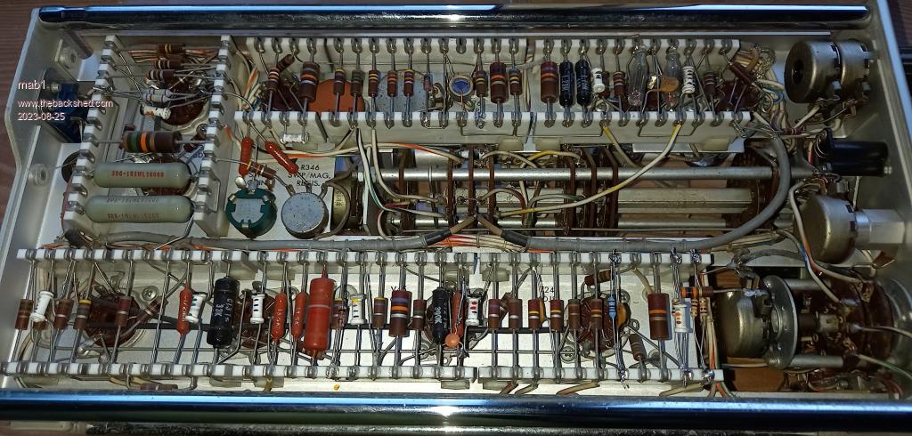
If it was a valve issue, I would expect the problem to ease as everything warmed up. However you say the longer the scope is on, the more you have to adjust the trigger control until you run out of adjustment. The symptom is typical of resistor drift due to heat. I would start with any of the older brown, rounded end resistors. These are a sponge with moisture. A picture of the component side of the module would be handy. Also, any of the old yellow wax capacitors (if fitted) would be the first things to replace. But a picture of the component side would help.
Cheers
Pete'. |
| |
mab1
Senior Member
Joined: 10/02/2015
Location: United KingdomPosts: 282 |
| Posted: 06:49pm 24 Aug 2023 |
Copy link to clipboard |
Print this post |
|
Hi pete L,
Just to clarify: the time i had to keep adjusting the level only happened once. Before that it was working normally iirc, and since then it hasn't worked at all, warm or cold.
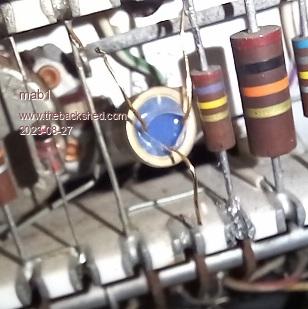
C37 22pF: my substitute is the small brown ceramic disk, approx centre on the lower tagstrip. The original is the cylindrical one alongside - it looks like it's still connected but thats just the pic.
Some good news: i found this in the manual for the mainframe:
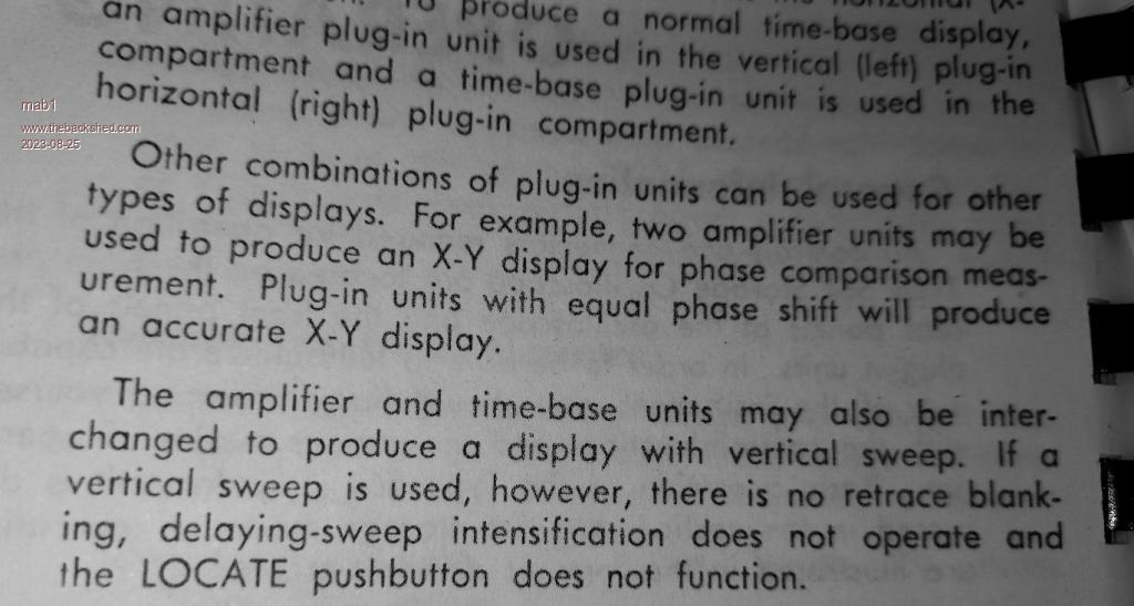
So it looks like i can plug the timebase in on the left and probe the voltages on the components  |
| |
Pete Locke
Senior Member
Joined: 26/06/2013
Location: New ZealandPosts: 184 |
| Posted: 05:32am 25 Aug 2023 |
Copy link to clipboard |
Print this post |
|
There's nothing in the picture that screams "Change Me". Someones been in there before looking at the newer style resistors. The tubular ceramic cap's are normally very reliable. At least now you have access for voltage checking. A quick run around the tube pins should lead you in the right direction. Good luck .
Cheers
Pete'. |
| |
mab1
Senior Member
Joined: 10/02/2015
Location: United KingdomPosts: 282 |
| Posted: 10:27pm 26 Aug 2023 |
Copy link to clipboard |
Print this post |
|
It's a GOAL!
Started testing static voltages, but the voltages i was seeing seemed reasonable and i didn't seem to be getting anywhere. So in the end i fired up the other valve scope and followed a trigger input signal until it stopped.
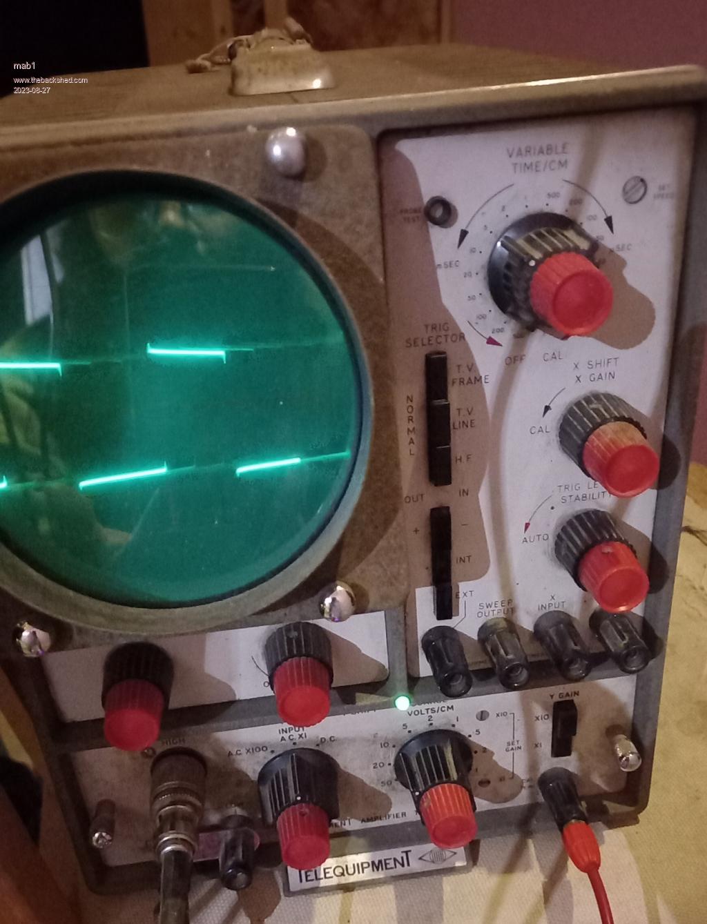
I do have a cheap Chinese pocket scope but it's only rated for 50vpp input.
The culprit: Q124 2N2043, the only transistor in the timebase, in the single sweep circuit. It seemed to check out with a diode test in circuit, but maybe i got b,c and e mixed up - i thought it was ok, but removing it from the circuit has got the timebase working.
Thanks for the contributions everyone, got there in the end. Although i still don't understand valve circuits really  |
| |
Godoh
Guru
Joined: 26/09/2020
Location: AustraliaPosts: 675 |
| Posted: 11:59pm 26 Aug 2023 |
Copy link to clipboard |
Print this post |
|
Nice work Mab. Glad to hear that you found the culprit.
Unfortunately many old valve devices get repaired and stuff changed over the decades.
I had a valve guitar amp once that had two channels. One was loud one much softer volume.
I worked for days on that thing, until I found an open circuit resistor that had been bypassed.
Instead of changing the resistor someone had jumped the connections to another resistor to pick up power from there. Which meant that one resistor was supplying power to two sections of the amp. It was odd that the amp worked at all, but putting the wire jumper back and replacing the dead resistor restored it to its glory.
Now I guess you will have to find a transistor that is a replacement for that one you found dead.
Have fun
Pete |
| |
pd--
Senior Member
Joined: 11/12/2020
Location: AustraliaPosts: 122 |
| Posted: 04:35am 27 Aug 2023 |
Copy link to clipboard |
Print this post |
|
Germanium PNP
https://www.electronicsurplus.com/motorola-inc-2n2043-transistor-pnp-p-n-2n2043
https://alltransistors.com/transistor.php?transistor=1507 |
| |
mab1
Senior Member
Joined: 10/02/2015
Location: United KingdomPosts: 282 |
| Posted: 01:56pm 27 Aug 2023 |
Copy link to clipboard |
Print this post |
|
Thanks  , i've ordered a new transistor, the fact that its pnp (and germanium) probably helped confuse me when i was testing. As was the fact that this part of the timebase differs slightly from the schematic: the schematics are for a later serial no. than mine, and whilst the table of components does list the values for earlier units, when a resistor is ommited altogether it doesn't say wether its a link, or open cct - turns out it can be either. , i've ordered a new transistor, the fact that its pnp (and germanium) probably helped confuse me when i was testing. As was the fact that this part of the timebase differs slightly from the schematic: the schematics are for a later serial no. than mine, and whilst the table of components does list the values for earlier units, when a resistor is ommited altogether it doesn't say wether its a link, or open cct - turns out it can be either.
Edited 2023-08-27 23:57 by mab1 |
| |
mab1
Senior Member
Joined: 10/02/2015
Location: United KingdomPosts: 282 |
| Posted: 02:07pm 27 Aug 2023 |
Copy link to clipboard |
Print this post |
|
Actually, i do wonder if i should make to mods to match the schematic for the later version - possibly it was changed to prevent failure of the transistor?
it's just changing one resistor and adding 3 more. Everything else in this part of the circuit is the same.
Edited 2023-08-28 00:08 by mab1 |
| |
