
|
|
Forum Index : Electronics : Low Power PV Charge Controller Designs
| Author | Message | ||||
| Solar Mike Guru Joined: 08/02/2015 Location: New ZealandPosts: 1162 |
Has been a while since I posted anything, too busy working on my long back log of projects, and now the bathroom has to be renovated... Recently I have been building and testing some smaller "Low" power MPPT charge controller designs, as I have quite a few small independent 12V systems to setup in the field, for controlling pumps, alarm sensors etc. They all seem to work ok, but are really over-complex for low power 12V 8 - 20 AH batteries fitted with a 10 - 30W PV panel. The smaller lead acid 10AH gel type batteries can only accept 1 amp or so of charge current, so its pretty pointless building a lower power MPPT device for them; its only where we have a larger battery like a free car battery that someone has donated and want to hook it up to an old 80-100 watt panel that may be 31 volts output, an MPPT controller works best. Looked at some of the EL-Cheapo small commercial controllers on offer, they are rubbish really and quite difficult to repair, as many are required its more cost effective to build your own, then I can somewhat over engineer things so it will last the next 10 years or so. Will use this Topic to post all my info on the lower power stuff. Design 1: Mini_PWM3, small pcb 75x82mm for a slow PWM type controller, using a Picaxe 14M2, PV charges the battery by switching 2 back to back mosfets via an isolated current to voltage driver chip, as used in SSR's. Mostly they are turned hard on, when the bulk stage moves to CV then float, they are pulsed enough to keep the battery voltage at the set points, which are set in the software. A 2nd high side mosfet is also used to supply the battery load, which maybe a small pump controller etc, this mosfet switch can be turned off to protect the battery from going completely flat if the PV or sun fails. The mosfet voltage driver chips are quite slow turning on, 1mSec perhaps a bit less, so slow PWM works best here. Currents up to 10amps shouldn't require any additional heat sinking. Anyway here is the schematic: 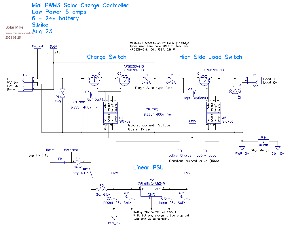 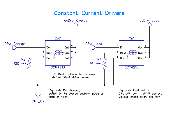 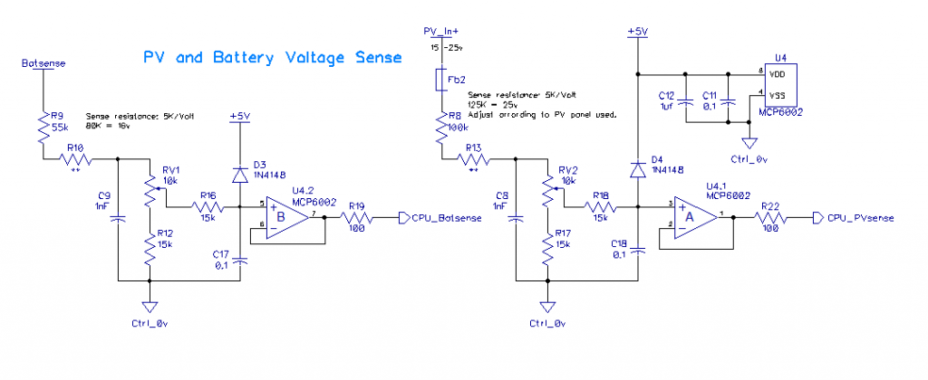 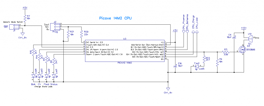 PCB, 75 x 82mm: 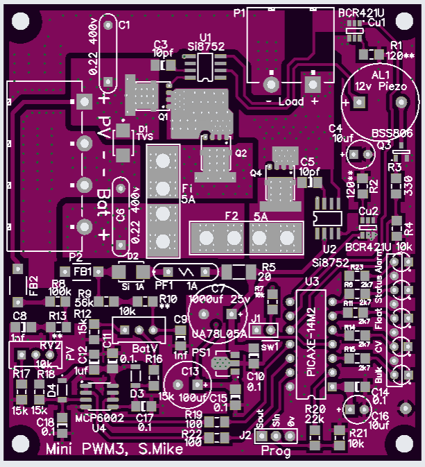  Sending the gerbers off now, will update later after testing. Cheers Mike |
||||
| Solar Mike Guru Joined: 08/02/2015 Location: New ZealandPosts: 1162 |
Mini PWM3 gerbers zipped: MiniPWM3.zip Part of this mini series is a small pcb 100 x 70mm Battery voltage relay type SSR using 3 pairs of dual mosfets in parallel, having a very low combined on resistance. The circuit is very similar to the PWM3 mosfet switching section. A Picaxe 08M2 used to monitor the battery voltage and turn off the loads should the battery volts get too low. With an alloy bar bolted under the mosfets, expect 50 amps would be no problem, limited to a max 24v battery, I was going to retro-fit it to some existing 12V installations supplying power to pumps. I have the pcbs back, but haven't tested it yet, sorry no schematic, I generally don't bother unless the thing is complicated. PCB: 100x70 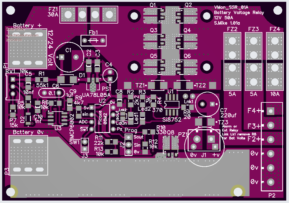  Gerbers: VMonitor_SSR01A.zip Cheers Mike |
||||
| Solar Mike Guru Joined: 08/02/2015 Location: New ZealandPosts: 1162 |
Here is the last variant of this version of Mini PWM, smaller foot print 72 x 60mm, less current capability and only a single status led to indicate what's going on. For the smaller 30W panels this will be fine. Currents above 5A will need a heatsink and allowed for by clamping an alloy bar to the lower pcb and some silpad material. I have bag of these 30 cent dual logic drive mosfets 30V @ 80A 5.2mR from LCSC, so have used them for the charge and load switch's, they don't require high voltage drive, so have opted for the cheaper TLP3906 isolated current to voltage mosfet driver, of which I also have a bag of. CPU is the 8 pin PicAxe 08M2. One thing you may notice is an input only pin C.3, being used as both an input and an output; achieved by program setting the pull-up silicon resistor on that pin and creating a voltage divider that drives the schmitt trigger logic buffer gate, affecting an output switch. 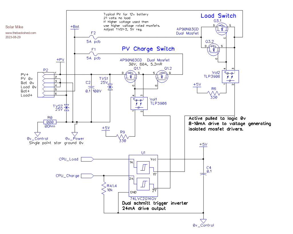 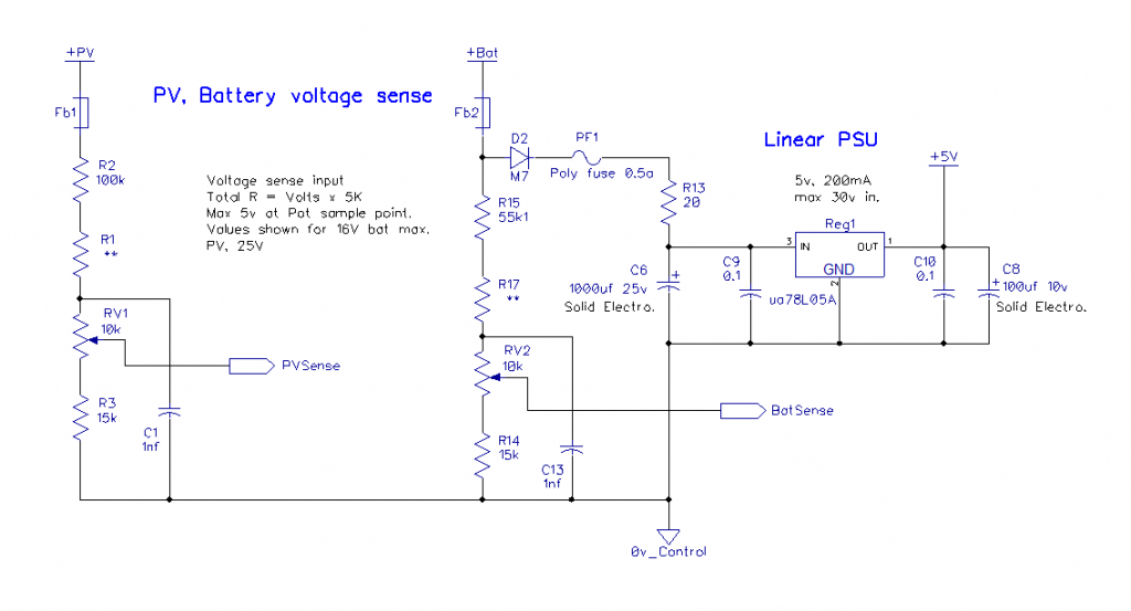 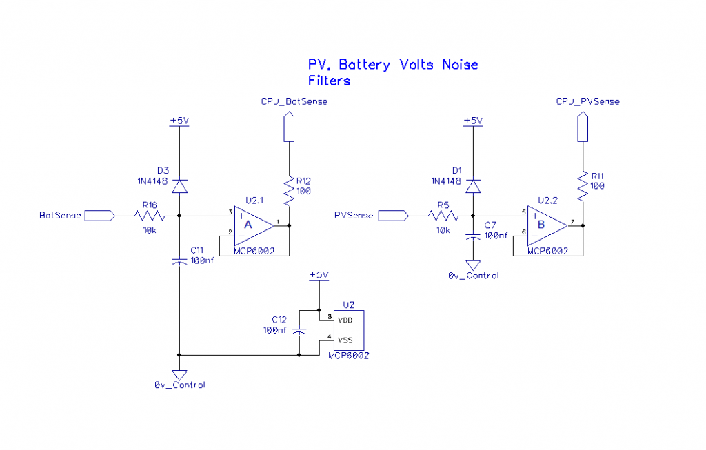 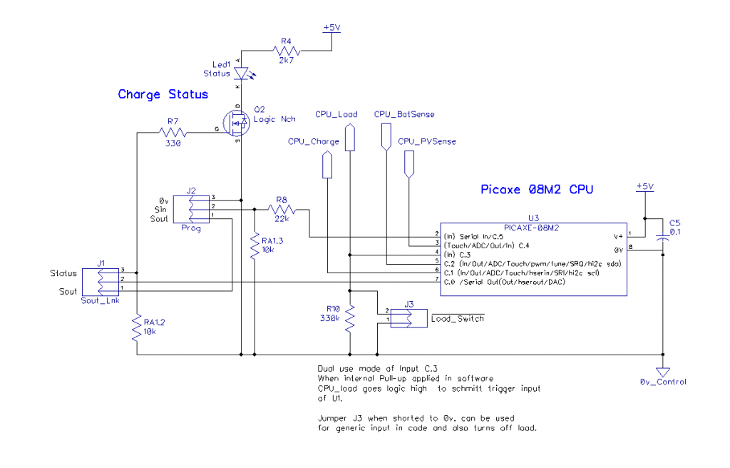 PCB 72x60mm: 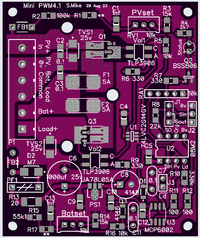 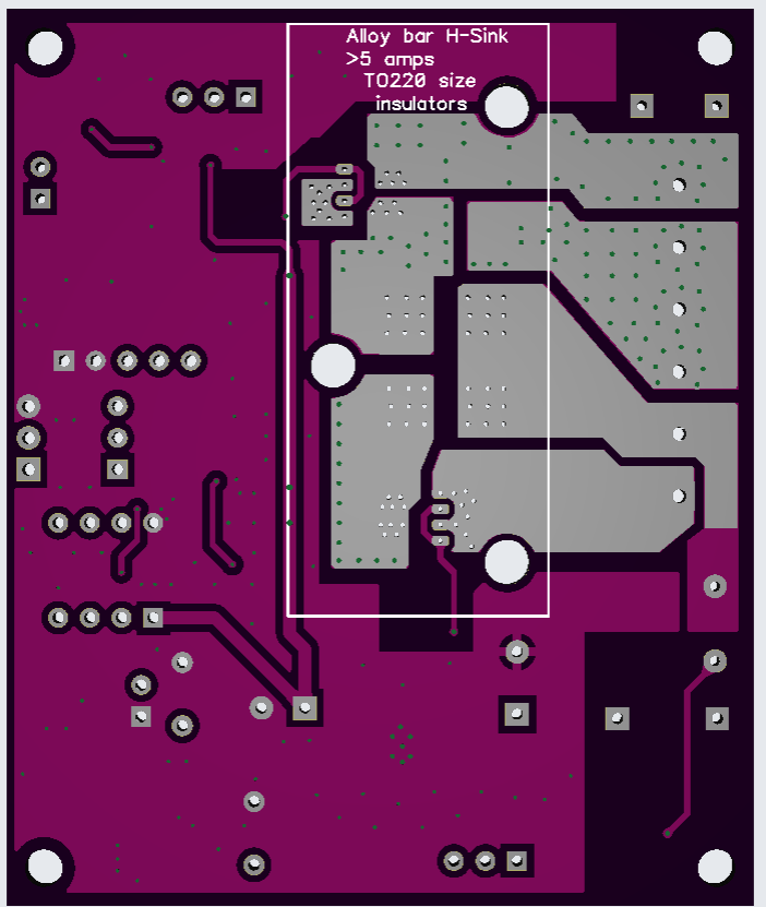 Gerbers: MiniPWM4.zip Cheers Mike |
||||
| Solar Mike Guru Joined: 08/02/2015 Location: New ZealandPosts: 1162 |
Here is the software for the MiniPWM4 above, have been doing some testing over the past couple of days, no changes required to pcb layout. Setup I was using was a 20 AH 12v gel battery and 30W PV panel, 17V loaded. Voltage sense resistors R1 = 20k, R2 = 100k, R15 = 47k, R17 = 2k7 Up to 5 amps charge current, no extra heat sinking is required. For higher currents, clamp the pcb to a silpad and alloy strip. PWM4_1A.zip Cheers Mike |
||||
| Solar Mike Guru Joined: 08/02/2015 Location: New ZealandPosts: 1162 |
Image of the built up pcb as used for testing. 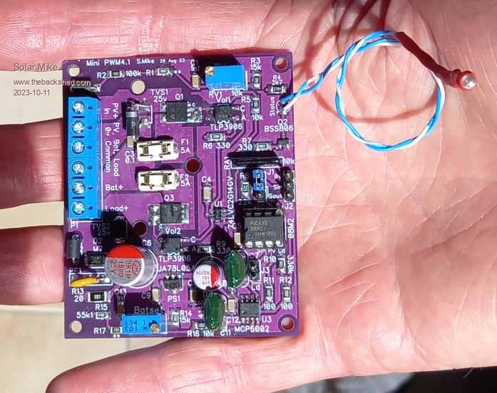 Cheers Mike |
||||
Revlac Guru Joined: 31/12/2016 Location: AustraliaPosts: 1153 |
That looks excellent Mike, any plans on a case to put it in.  Cheers Aaron Off The Grid |
||||
| Solar Mike Guru Joined: 08/02/2015 Location: New ZealandPosts: 1162 |
No I don't have a specific case for it, as its going into a box with other items, I was going to spray it with a conformal coating varnish to keep the moisture out. Currently making another version that uses a shunt pwm switch circuit for use in charging lower power small batteries eg 12v 2AH; by doing away with the high-side switch mosfet drivers which draw 10mA each. A couple of the installations only have 10 watt PV panels and a small 12v Lifepo4 battery. Will have a look at what small cases are available, it would be trivial to alter the pcb to fit. Hmm... 3D printer for Christmas. |
||||
| Solar Mike Guru Joined: 08/02/2015 Location: New ZealandPosts: 1162 |
AliExpress have a number of inexpensive plastic cases with clear lids, Link I have completed another layout that fits into one that's 115x90x55mm; as I prefer to have a few leds to indicate state of charge progress, have opted for a bigger CPU, Picaxe 14M2, this allows more options with IO. This design (shunt Regulator) will use true PWM (10bit) for controlling the charge voltage, have changed the mosfets and a faster driver. Went straight to pcb on this one, but will draw up a schematic in the next day or so. Top: 78x85mm 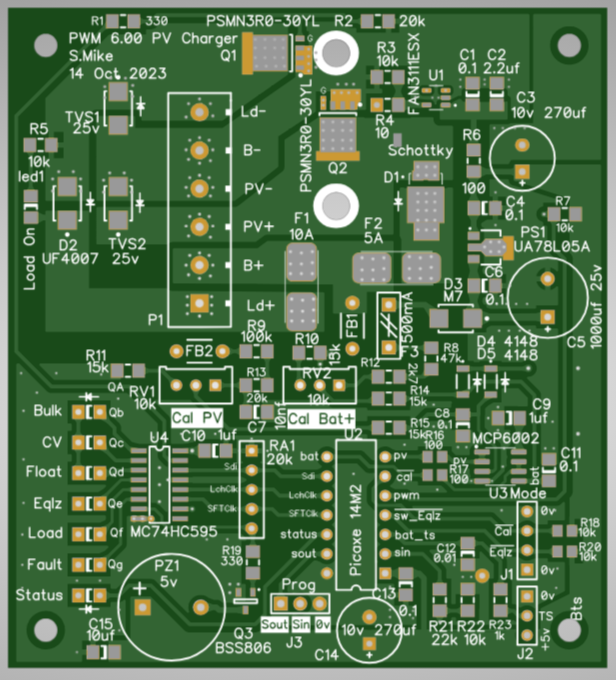 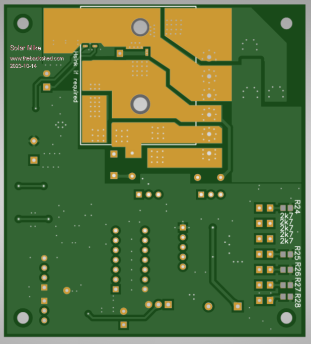 Cheers Mike |
||||
| Solar Mike Guru Joined: 08/02/2015 Location: New ZealandPosts: 1162 |
Here is the schematic, couple minor changes to the above pcb also. 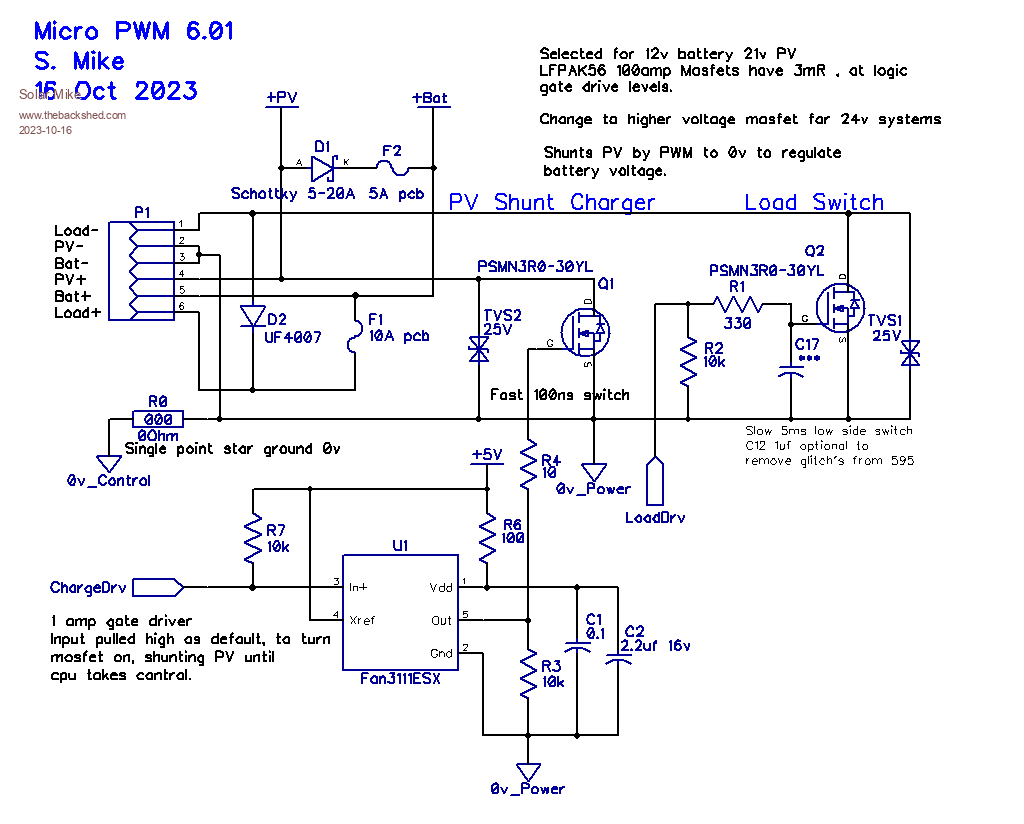 I wanted to eliminate the current to voltage mosfet drivers, as when running off small batteries, there is less standby loading when not under charge. So opted for a shunt PWM regulation, where the PV panel is shorted to turn it off, the mosfets I have used don't require a lot of drive to transition them, thus the tiny Fan3111ESX driver used. PWM frequency will be approx 1Khz, the PWM only being active after the bulk charge point. Load switch mosfet can be slow turn on\off, so no driver is required. 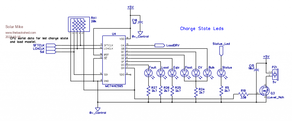 Serial to parallel converter used here to drive the charge status leds. 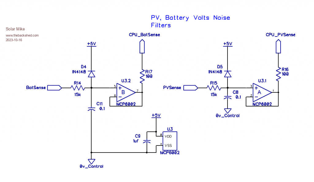 Simple op amp buffers used here to filter out noise from the battery and PV sense, this also presents a low impedance drive to the cpu's ADC inputs. 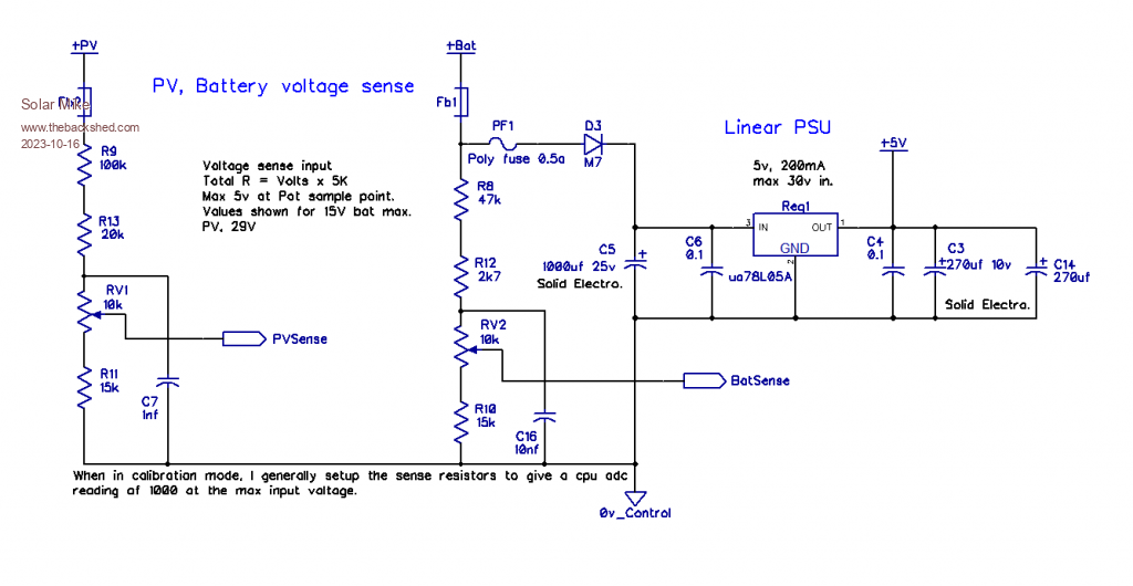 Voltage sensing and PSU, intended for mostly 12 or 24V batteries, the 5V regulator chip has to be selected for sufficient input voltage rating. Solid electro's in the PSU work best in these applications as they have superior low impedance and thus noise prevention over your common electro caps. Common 0v traces should be also differentiated between high current (Power) and control, with no top bottom layer overlaps; star grounds. 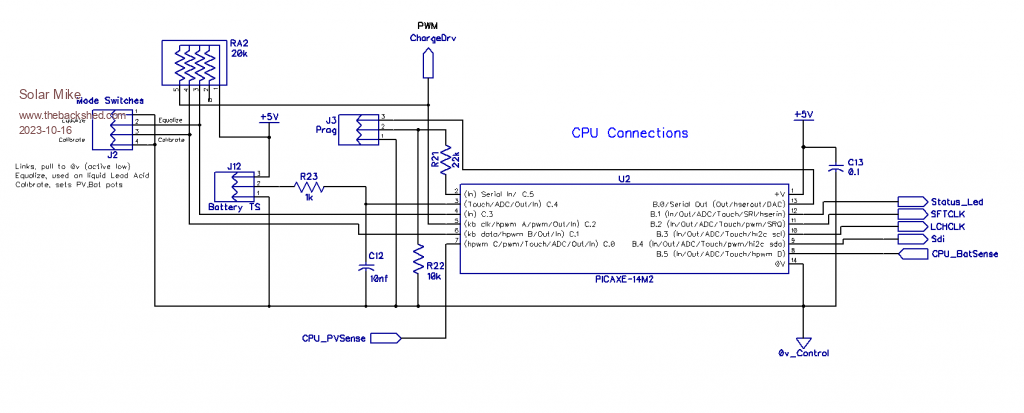 Have made provision for a battery temperature sensor and a battery equalize switch input, not required at this end, I won't coding for them. PCB images, JLCPCB gerber viewer appears broken again, was working ok few days ago, they keep fiddling with it and always seem to make it worse than before, now I can see why Chinese EV cars have such crappy software. Top: 78x85mm 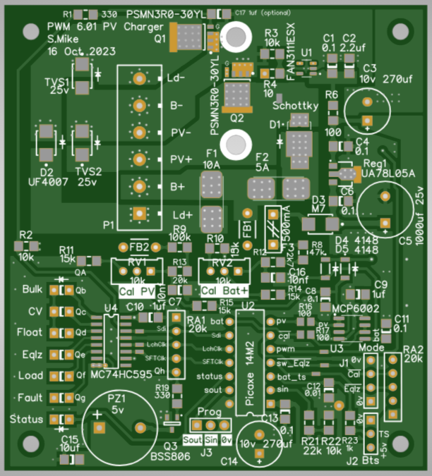 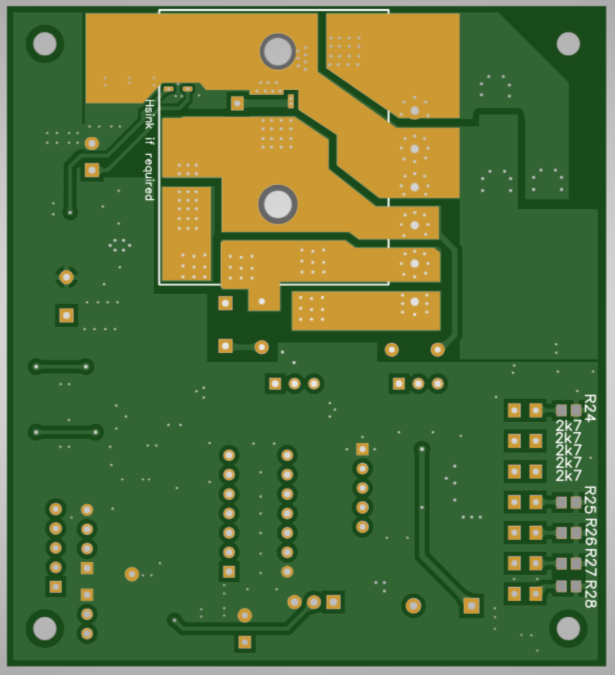 Anyone wants the gerbers, send me a PM. Cheers Mike Edited 2023-10-16 18:26 by Solar Mike |
||||
| The Back Shed's forum code is written, and hosted, in Australia. | © JAQ Software 2025 |
