
|
|
Forum Index : Electronics : High idle power revisited
| Author | Message | ||||
| Murphy's friend Guru Joined: 04/10/2019 Location: AustraliaPosts: 671 |
A while back I posted about my 6KW inverter having an unexpectedly high standby power. This I 'cured' by increasing the dead time capacitor. This inverter is now powering my house and working fine but wiseguy and others were not convinced I made the right 'cure'. Now, experimenting with my 3 KW inverter, which is very similarly built, just a smaller toroid transformer, I notice it too had an unacceptable high idle power. Worse than my big inverter had in fact. Sooo, having time on my hand, I started checking parts. Nothing faulty was found, dead time capacitor changes made little difference and in the end the problem was pinned to the mosfets alone. They are mounted on carrier boards so they can be exchanged without resorting to messy soldering fixes (one of my better ideas  ). ).Here is how they look, there are four identical boards: 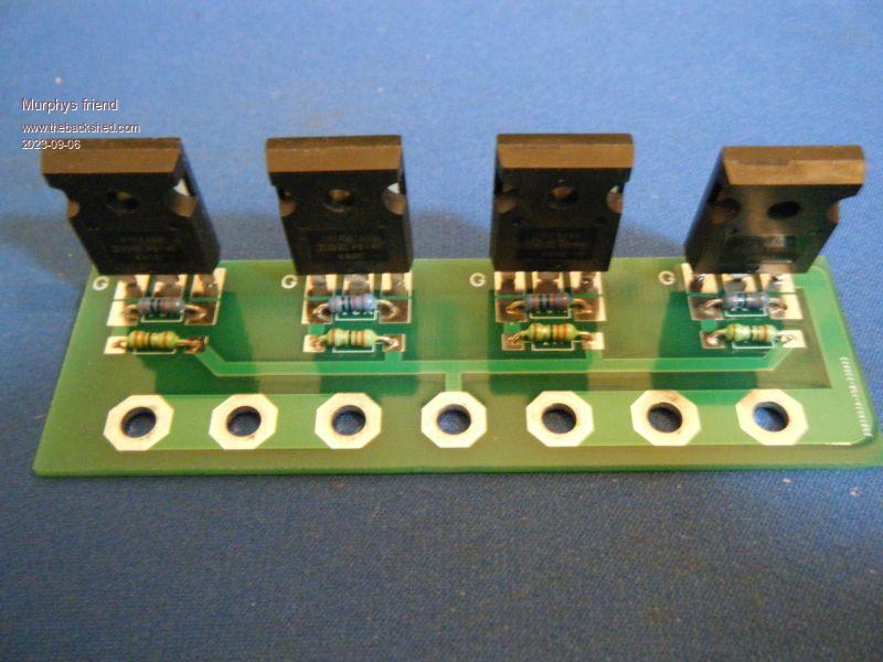 This board is fitted with IRFP4468PbF mosfets. All 4 boards test faultless when driven by a 20KHz, 50% duty cycle square wave. As load I used LED car brakelights with suitable dropping resistors so testing could be done at 55V DC. But, driving the mosfets from the symmetrical control board output (either NANO or EG8010 derived), the inverter takes too much idle power. Now the really strange thing, if I replace those carrier boards with ones fitted with new HY4008 mosfets the idle power is where it should be. As the IRFP4468's had been in use for some time previously I wonder if these things change in some way. Still switching 20KHz square waves but not what the control board feeds them. Or is it something entirely different? |
||||
| poida Guru Joined: 02/02/2017 Location: AustraliaPosts: 1432 |
I see a rather large difference in turn on (& off) delay and rise times between the IRFP4468 and the HY4008 The test conditions for the parts are different so it's apples and oranges but it surely must give some guidance... IRFP4468: tested at Vgs = 10V, Rg = 2.7 Ohms turn on delay: 52ns rise time: 230ns turn off delay: 160ns fall time: 260ns HY4008: tested at Vgs = 10V, Rg = 6 Ohms turn on delay: 28ns rise time: 18ns turn off delay: 42ns fall time: 54ns clearly the HY4008 will switch a lot faster than the IRFP4468 total Gate charge is 195nC for the HY4008 and 360nC up to 580nC for the IRFP4468 I think the slower switching IRFP4468 require a longer deadtime than what you have designed. The shoot through is causing the high idle power consumption. Edited 2023-09-06 20:08 by poida wronger than a phone book full of wrong phone numbers |
||||
| Murphy's friend Guru Joined: 04/10/2019 Location: AustraliaPosts: 671 |
Thanks Poida, your expertise is very welcome. At last I have an explanation, in my ignorance I did not check these important specifications. I will do some more research with larger dead time capacitors. I wonder if you could do me a favor and check the data for an IPTC014N10NM5 with respect to possible dead time problems. I'm considering using those for a compact inverter. |
||||
| poida Guru Joined: 02/02/2017 Location: AustraliaPosts: 1432 |
IPTC014N10NM5 seems to be fast switching and moderate Gate charge. Vgs = 10V Rg 1.6 Ohms turn on delay: 36ns rise time: 30ns turn off delay: 85ns fall time: 30ns 168 nC total Gate charge it appears that to get this fast switching you will need a high current Gate drive design, and use 1.6 ohm resistors to drive them hard. 100V, 1.4 mOhm and very large pulsed current rating, over 1000 Amps.. I can't help but suggest you get a decent DSO to observe deadtime as seen at the FET's Gate pins to be completely certain there is no shoot through from your designs. wronger than a phone book full of wrong phone numbers |
||||
| Solar Mike Guru Joined: 08/02/2015 Location: New ZealandPosts: 1162 |
Those IRFP44XX series mosfets have a multiple die arrangement inside them, the resulting large gate charge characteristic requires a very meaty gate driver; as you have 4 in parallel then perhaps your driver chip or transistor buffer cannot supply enough current to get them to switch quickly, needs to supply >10 amps peak @12v. As Poida say's you need a good scope to test this. |
||||
| Murphy's friend Guru Joined: 04/10/2019 Location: AustraliaPosts: 671 |
Thanks poida, appreciate your comments. A Rigol DSO like you have would be nice but its outside my hobby fund range. I was looking at the Hantec DSO and wonder if that would be suitable, also what kind of probes will I need to see the switching at the gates of both mosfets since they have no common ground? |
||||
| Murphy's friend Guru Joined: 04/10/2019 Location: AustraliaPosts: 671 |
It won't let me update my last post but its this DSO |
||||
| Murphy's friend Guru Joined: 04/10/2019 Location: AustraliaPosts: 671 |
Sorry about the no find link above - this forum's editing feature does not like me. Anyway, I was looking at a Hantec DSO2C10 |
||||
| poida Guru Joined: 02/02/2017 Location: AustraliaPosts: 1432 |
yes, something like that will do the job. 2 channels and external trigger input. Assuming your gate drive supply is 15V... set both channels to 5V/div ch1 is on the low side Gate, the ground clip is on DC supply ground now, to get the high side Gate signal, we must keep in mind that this signal rides on top of DC+ supply, potentially 57V The Gate signal goes from 57V to (57V + 15V) again, put ch2 ground clip on DC supply ground. I am lucky to have some isolated probes, which can be used to remove this 57V offset. But when you don't have these, you need to use the DSO vertical offset to the maximum to bring the high side Gate signal to the same DC level as the low side. I see in the Hantec's user manual the offset range is +/- 50V for 0.5V to 10V/div and so this is just what you need. Set both channels to 5V/div, use the offset to bring the high side gate down 50V. Line up both signals vertically and then you will be able to see the two Gate drive voltages. as the FETs are switched on and off. This will show if there is much overlap (causing shoot through and high idle loss) you could have test setups that feed a constant PWM width, in which case you could just use ch1 to trigger off of. Or maybe you want to see how it goes for an entire 50Hz output cycle (approx 400 PWM pulses), so I would use the 50Hz square wave output from the EG8010 or pico/nano to trigger off, using the external trigger input function. The DSO has 4M memory when using both channels so it will give you a good view of what is going on over a long period of (sample) time. wronger than a phone book full of wrong phone numbers |
||||
| Murphy's friend Guru Joined: 04/10/2019 Location: AustraliaPosts: 671 |
Wow poida, info like this is gold for somebody like me. Thank you for taking the time, I have printed out your reply to have handy when I get my hands on that DSO. Regarding my high idle power problem, your suggestions did the trick  . .Using 2.2 Ohm gate resistors and 10nF dead time capacitors the idle power of this 3KW inverter is now 19W, running with 16 IRFP4468 mosfets. And I learned a fair bit in the process to getting this result, thank you all for your valuable input. |
||||
| The Back Shed's forum code is written, and hosted, in Australia. | © JAQ Software 2025 |
