
|
|
Forum Index : Electronics : my new simple inverter
| Author | Message | ||||
| poida Guru Joined: 02/02/2017 Location: AustraliaPosts: 1389 |
I want a small low power inverter to make coffee in the campervan. The coffee machine is a Breville Barista Express and needs 1600W to heat up. Or at least that was the excuse. It's all in one, except for the 15V supply. With a 12V battery, a boost converter is needed. 48V supply needs a buck. I was not going to put a buck/boost on it. Only one HY4008 per leg of the bridge means it's good for about 1000W easy and maybe 2000W peak. Testing will show if it's up to the job. I just built it and it has good output. It runs picoverter code. This is at 52V DC supply. 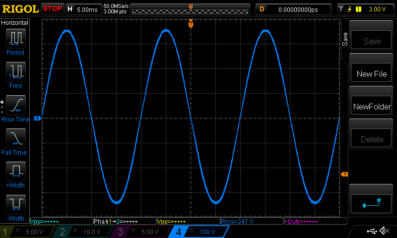 with 240V output, it's only 0.22 Amps at idle. 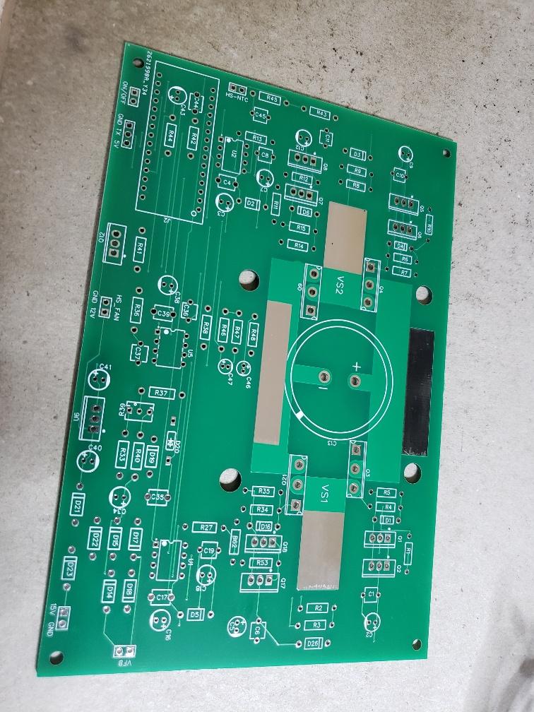 thought I would put the portable DSO on it. (danger: all grounds on that device are connected, including the USB charge port so that means the USB port is 240V AC relative to one of the inverter's output) 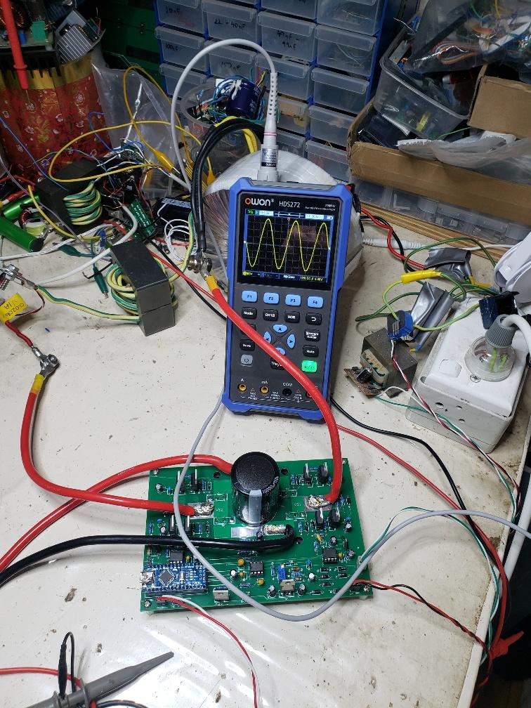 The Gate voltages are really nice and clean. Here is the low and high side for one of the half bridges. Dark Blue is high side, Light Blue is low side High side vertical scale should be 5V/div not 40V as shown. 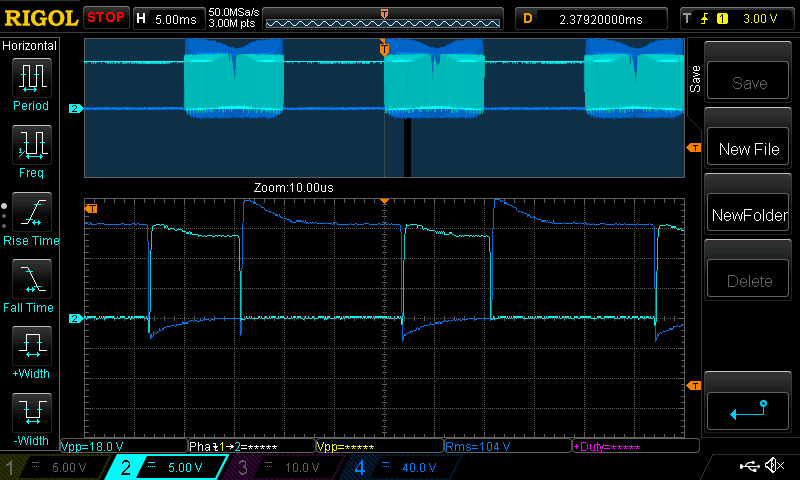 Edited 2023-10-22 15:09 by poida wronger than a phone book full of wrong phone numbers |
||||
| Murphy's friend Guru Joined: 04/10/2019 Location: AustraliaPosts: 589 |
Nice, all on one PCB  . .In my past experiments with a just 4x HY4008 Mosfet bridge your estimated 1000W was about right, but they were on heat sinks. They did blow when I pushed them past the 1KW level. |
||||
| poida Guru Joined: 02/02/2017 Location: AustraliaPosts: 1389 |
I will put them on a heatsink. Just did a test for efficiency at 200 Watts The HY4008 FETs barely warm up past room temperature without heat sinks. a load 202 W draws 4.22 A @ 51.3V (216.5W) this is 93% including the zero load loss zero load is 0.22 A @ 52.2V or 11.5W When I remove the toroid, the no load drops to zero. this means little or no shoot through at low loads. with a 410 W load, it needs 8.07A at 53.7 V or 94.6% efficient here is the AC waveform at 400W (1.0 power factor) 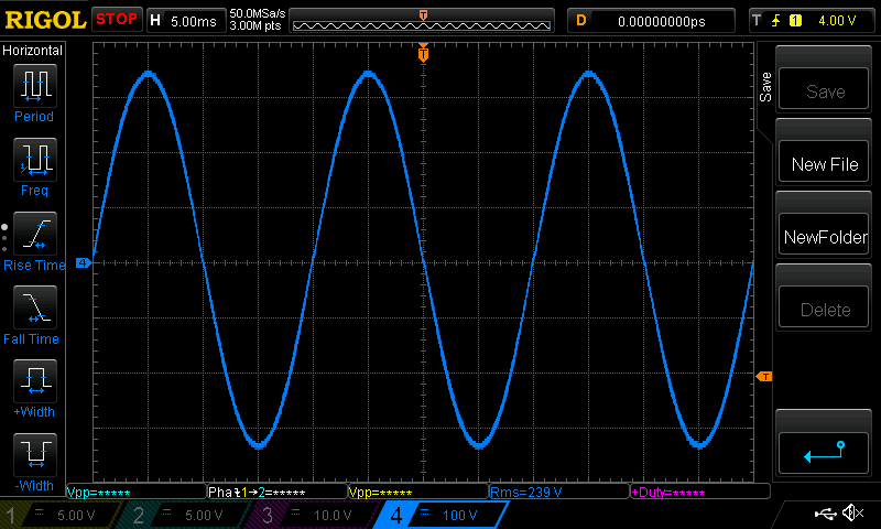 It's remarkable that the FETs stay nearly room temp, even with 20 second tests at 400W. The Victron 12/375 needs to run its fan with 100W loads. This is a good result. Edited 2023-10-22 21:32 by poida wronger than a phone book full of wrong phone numbers |
||||
| poida Guru Joined: 02/02/2017 Location: AustraliaPosts: 1389 |
it makes coffee the video of making the goodness when pulling 1500 Watts. No problem. But we need headroom - proof that it is comfortable at this power level. So I connect the 10 Amp hot water urn which needs 2400 W no fireworks, it just works. video of this test The toroid I will use in the campervan is from a sh1tty power-whatever thing rated at "something huge & not realistic" Watts. It ran the fan under 200W loads. a piece of crap. The primary has a few too many windings so 240V output is only possible when input DC voltage is about 50.4V or higher. And it gets warm quickly. No matter, I will do my own primary, and size the ratio to suit my expected voltage droop under high loads. 2400 W at about 50V DC means average current is 48 Amps The PWM follows a sine wave shape so the peak is 48 x 1.414 Amps or 68 Amps The PWM modulation is nearly 100% with my test setup so at the top of the sine wave, PWM is nearly 100% continuous on. My inverter design has one 1/2 bridge with low side ON, pulling an output to ground while the other output follows the 1/2 sine wave. The power is flowing through one low side FET (on for 1/2 cycle) and the other output' high side FET doing PWM. In effect this 2400 W is flowing through 2 FETs, in series. Safe operating area from the HY4008 specs is this: 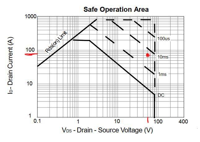 The 1ms and 10ms needs to be swapped, they made an error when doing the graph. The Red dot is 70 Amps at 50V which is the peak power point of the test. What is the duty cycle width for these safe operating area graphs? anyone here know? I think the 2400 Watt test is getting right up there to the device limits. The heat sink got a small amount hotter than ambient. Building in a fan will make it robust at my estimate of 1500 Watts continuous. wronger than a phone book full of wrong phone numbers |
||||
| pd-- Senior Member Joined: 11/12/2020 Location: AustraliaPosts: 122 |
Its a single non repetitive pulse. But with the FET on and passing 70A you would not have had a 50v drop across drain Source |
||||
| poida Guru Joined: 02/02/2017 Location: AustraliaPosts: 1389 |
one day I will understand this. I suppose Drain-Source voltage would be DC supply minus whatever is output into the primary. The PWM system of ours is repetitive so how to work out what is OK according to specs? I just showed that 2500 Watts at 50V through one FET is possible. But I would like to know that it's "acceptable" from the manufacturer's point of view. wronger than a phone book full of wrong phone numbers |
||||
| phil99 Guru Joined: 11/02/2018 Location: AustraliaPosts: 1801 |
As @pd-- noted the graph is for the simultaneous combination of Id and Vds so mainly applies to the switching transition when both Vds and Id are significant. As that lasts much less than 100uS you are on safe ground. Edit For a simple resistive load that will be 68 / 2 = 34A and 50 / 2 = 25V For a complex load with very low PF (eg an induction motor at start-up) you may be closer to the limit. Edited 2023-10-23 22:10 by phil99 |
||||
