
|
|
Forum Index : Electronics : CT question
| Author | Message | ||||
| azhaque Senior Member Joined: 21/02/2017 Location: PakistanPosts: 131 |
I have a CT of unknown origins. I want to connect it to a u-controller to measure AC current. An ohmmeter connected to its output terminals reads 59.1 ohms. What value resistor should I connect across it's terminals so that the voltage across the resistor is proportional to the current flowing in the primary. Please explain with an equation for using in an arduino program. TIA Azhaque Edited 2023-10-29 18:49 by azhaque |
||||
| oh3gdo Regular Member Joined: 18/11/2021 Location: FinlandPosts: 47 |
azhaque Pleas start measuring with low current like 0.1A and low secondary resistor like 100 ohms. Measure the voltage after rectifier. When you see a little voltage you can add the resistor to 1 kohma or more. I think that the CT is 1:2000 like normal, but you must start with low resistor current.pdf Here is one amp and 1:2000 ct conncetion Regards Pekka Ritamaki |
||||
| azhaque Senior Member Joined: 21/02/2017 Location: PakistanPosts: 131 |
Thanks a million for the reply Pekka. Just to take the discussion a step fwd here are the pics of the ct 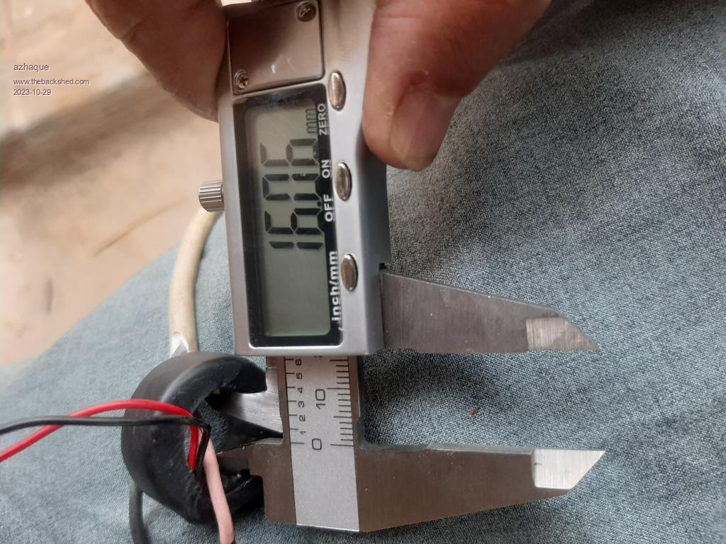 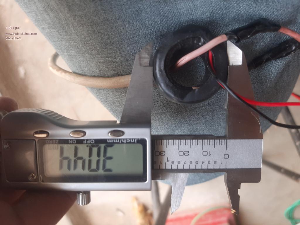 The inner and outer dias. of the ct are 16 and 30 mm respectively. A supplementary question is what kind of a rectifier bridge should be used. A silicon based one will have a cumulative voltage drop of around 1.5 volts. How do I iron out this drop in the software. Regards Azhaque |
||||
| SimpleSafeName Guru Joined: 28/07/2019 Location: United StatesPosts: 351 |
Most (old school) CTs are ones that have a ratio of "X" to 5 amps. That could be 100:5, 500:5, 1000:5, whatever. Always keep in mind that the secondary is intended to be connected to a load at all times. The reason for this is that if you have say, 100 amps going through the primary of a 200:5 CT, then the secondary is doing its darndest to pump 2.5 amps out on the secondary. But if you have the secondary open, you potentially have 2.5 times infinity (or thereabouts) of volts building up to complete the circuit. Not understanding this has been known to provide memorable zaps to unsuspecting personnel, cause fires (one of the companies that I have worked for in the past made it to the 10 o'clock news one night...), or do both. At the very least, it's hard on CTs. So if you take nothing else any from my babbling, it's that shorting a CT's secondary is what you need to do before working on it (they make shorting bars just for this purpose). And here is a datasheet from one CT manufacturer that might help: https://www.crmagnetics.com/Assets/ProductPDFs/CR8400%20Series.pdf It has a chart for taking the dimensions of the CT and figuring out what the model number is (for that brand of CT). For what they cost, I would get a new one. |
||||
| phil99 Guru Joined: 11/02/2018 Location: AustraliaPosts: 3317 |
Unlike "proper" CTs those tiny ones saturate at quite a low output voltage. They also become very non-linear if the burden resistor is too high. Without it's data sheet it will be necessary to make a test rig to work out it's ratio and maximum resistance for linear output. |
||||
| SimpleSafeName Guru Joined: 28/07/2019 Location: United StatesPosts: 351 |
Yup. Not really worth the effort when you factor in how cheap a new one is. And then having to adjust your design based on what the CT ends up being. We had a guy forget to short out the secondary on a 10 story (IIRC) apartment complex and burned it to the ground. That was the event that made the news. :) |
||||
| azhaque Senior Member Joined: 21/02/2017 Location: PakistanPosts: 131 |
Thanks for input guys. Phil- for my understanding, 'too high' means too high a burden (meaning low value resistor) or its opposite. Azhaque Edited 2023-10-31 00:49 by azhaque |
||||
| Ziki_the Newbie Joined: 13/04/2023 Location: YugoslaviaPosts: 39 |
Think it's opposite. Go with low value. :) Pozdrav iz Srbije |
||||
| phil99 Guru Joined: 11/02/2018 Location: AustraliaPosts: 3317 |
Yes, with CTs it's the opposite of PTs (voltage transformers) a low value across the output gives best linearity. However a low resistance also reduces the output voltage so for very small CTs sometimes an op-amp is needed to boost it to a useable value. Some testing will be needed to see what it can do. Search online for ones with similar dimensions and see what their specifications are. That may provide a starting point. Edit If the CT output is high enough a bridge rectifier can be put between the CT and resistor. If put after the resistor it adds its own nonlinearity. Use Schottky diodes for lowest loss. Edited 2023-10-31 07:51 by phil99 |
||||
| azhaque Senior Member Joined: 21/02/2017 Location: PakistanPosts: 131 |
Thanks for the detailed response Phil. As suggested, scouring the Net I believe I have found the exact data (God bless Aliexpress and China- Pakistan free trade agreement) for the CT. 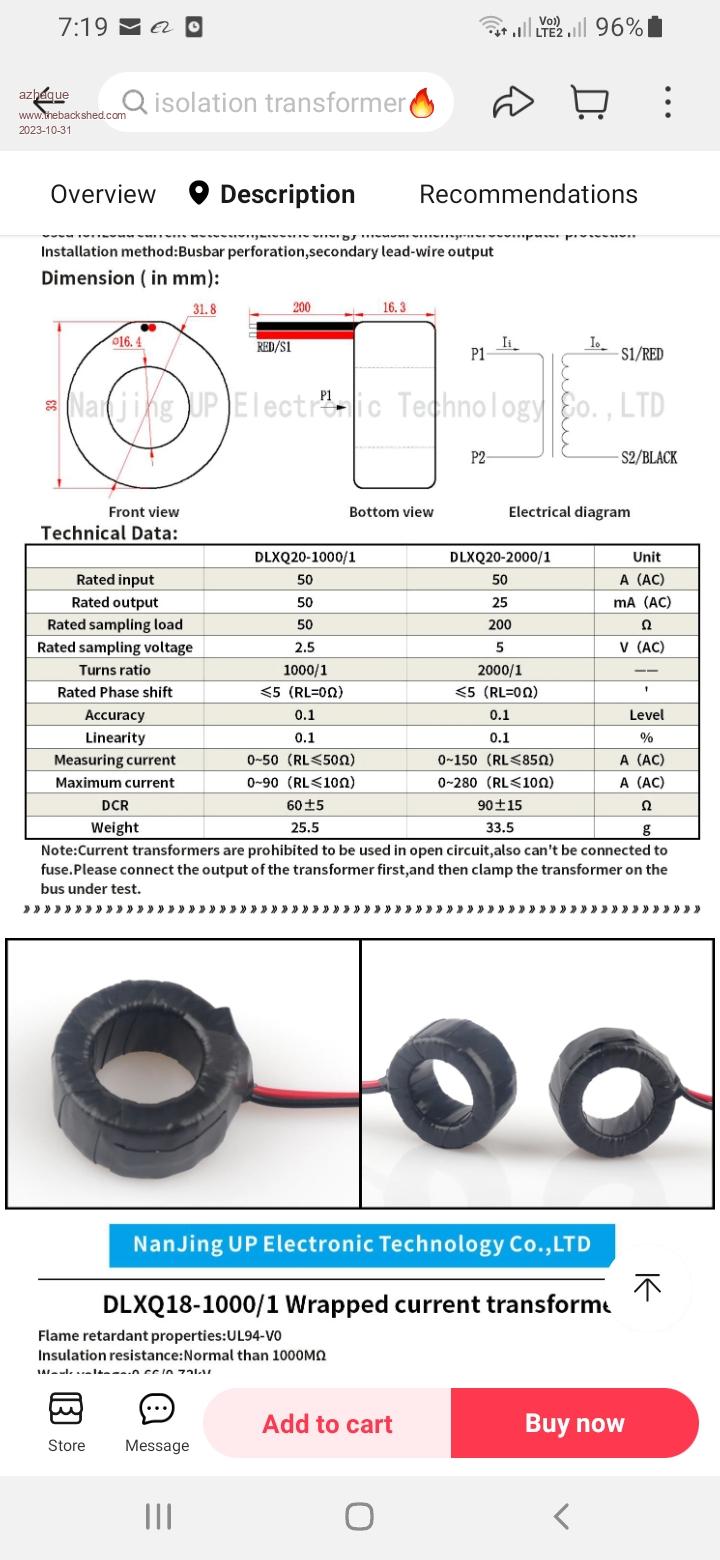 The sizes and the internal impedance match. As per the datasheet the burden resistor should be 50 ohms with 50A/50mA ratio. It will develop 2.5 volts across the burden, which is slightly on the lower side. Full wave rectification should output 2.5*1.4=3.5v peak which isn't too bad for a 4x1N4004 type bridge. The u-controller should be able to read the values comfortably with adequate resolution. Thanks again guys. Azhaque Edited 2023-10-31 12:35 by azhaque |
||||
| The Back Shed's forum code is written, and hosted, in Australia. | © JAQ Software 2026 |
