Notice. New forum software under development. It's going to miss a few functions and look a bit ugly for a while, but I'm working on it full time now as the old forum was too unstable. Couple days, all good. If you notice any issues, please contact me.
CraziestOzzy Senior Member Joined: 11/07/2008 Location: AustraliaPosts: 152
Posted: 10:29pm 25 Mar 2009
Copy link to clipboard
Print this post
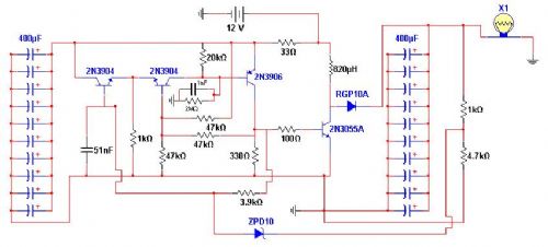
Just manipulating a general schematic for a charge pump capacitor taken from the web.
Charge pump capacitors generally increase voltage on the output side.
I am wanting to control the rate of capacitor energy discharge.
I changed a few things around to have roughly the same amount of volts coming in through the battery and the same coming out. Reality is, I loose 0.4 volts out of the 12 volts on the output side.
The main aim here is to increase the amps on the output side, using the caps as a sort of reservoir for energy while keeping voltage levels on the output close to the input levels.
The amps raised are insane, so I am going to have to change some components to suit.
Currently adding some noise filters and working on a dump for excess, so this really is a work in progress.
Edited by CraziestOzzy 2009-03-27http://cr4.globalspec.com/member?u=25757
http://www.instructables.com/member/OzzyRoo/
GWatPE Senior Member Joined: 01/09/2006 Location: AustraliaPosts: 2127
Posted: 10:51pm 25 Mar 2009
Copy link to clipboard
Print this post
I really don't see what you are trying to achieve here. The 33ohm resistor serves what purpose? The 2N3055 has relatively low gain and requires significant drive current that does not get to the load. I see many low value resistors and this is not normally good. What sort of power does X1 require. [is this a fillament lamp?]
I am guessing that this is going to be some sort of dump load controller. The 4800uF @12V is not a lot of energy.
What would you consider insane amps?
Gordon.become more energy aware
CraziestOzzy Senior Member Joined: 11/07/2008 Location: AustraliaPosts: 152
Posted: 11:43pm 25 Mar 2009
Copy link to clipboard
Print this post
...as for the rest, may I suggest you look up what is a charge capacitor, read my description above for voltage output levels for X1, including other details where I mention the need to change some components to compensate for the increased power levels and brush up on your schematic symbols at least of all things...cheers
Edited by CraziestOzzy 2009-03-27http://cr4.globalspec.com/member?u=25757
http://www.instructables.com/member/OzzyRoo/
GWatPE Senior Member Joined: 01/09/2006 Location: AustraliaPosts: 2127
Posted: 03:11am 26 Mar 2009
Copy link to clipboard
Print this post
Go for it. You don't seem to need any help.become more energy aware
CraziestOzzy Senior Member Joined: 11/07/2008 Location: AustraliaPosts: 152
Posted: 11:22am 26 Mar 2009
Copy link to clipboard
Print this post
Now that I am off my nasty pills , the 2N3055 transistor is indeed archaic and in need of replacement. Even the 2N3904/6's are miles too small to handle anything decent. I did mention earlier a need to improve capacity of some components.
The values of the resisters appear small, but are necessary in my view for the gates. I may need to strengthen them with some good ceramics or run a few in parallel during bench testing.
Basic concept here is using the schmidt transistor arrangement as a switch type trigger to move power from the source to the outlet...while increasing energy potential instead of increasing voltage output as is the norm.
The 33 ohm resistor in my view is misplaced by original author and more likely be moved to the 2N3904 input out of the direct circuit to the capacitors. Well picked up.
Capacitors on both sides act like a filling and emptying bucket scenario...one bucket (capacitor bank) fills, while the other empties. Both are neither completely full or empty at any stage.
I am open to any constructive criticism, thoughts and experiences regards to similar.
Cheers
Edited by CraziestOzzy 2009-03-27http://cr4.globalspec.com/member?u=25757
http://www.instructables.com/member/OzzyRoo/
davef Guru Joined: 14/05/2006 Location: New ZealandPosts: 499
Posted: 07:52pm 26 Mar 2009
Copy link to clipboard
Print this post
OK, I'll try! That left bank of caps. I can only see that they will hold up the supply voltage on the low power side of the circuit. Any charge they hold would only effect the drive to the 2N3055 via the 100 Ohm resistor.
Maybe it would provide some benefit at very low switching frequencies.
GWatPE Senior Member Joined: 01/09/2006 Location: AustraliaPosts: 2127
Posted: 10:12pm 26 Mar 2009
Copy link to clipboard
Print this post
The use of X is normally associated with a crystal. The image you have associated with this appears to be a lamp. You have made no attempt to clarify this.
The normal way of controlling the charging/discharging of capacitors is with a constant current source/sink cct.
The cct you have posted above, is basically a voltage stabilised oscillator on the left. The output voltage sensed is used to control the oscilator to give duty cycle control to the 2N3055 switching transistor. This is a flyback voltage boost cct.
The fact that the voltage you measure is 0.4V lower than the battery indicates that the load is greater than the switching cct can sustain.
I use PWM type voltage boost ccts on my original AxFx windmill to allow 24V battery charging from as low as a 7V windmill output. As a comparison, the capacitance on the windmill side of my cct is 4 x 4,700uF with 2 x 470uF on the battery side. The modulator cycles at the lowest voltages as the capacitors absorb the windmill output power, before the mosfet switching transistor/inductor/steering diode transfers the charge stored on the windmill caps to the battery. This PWM cct consumes between 20-40mA from 0-500W power transfer between the windmill and the battery. I am now using a SMD 150A @ 60V mosfet. Obviously there are no heatsinks here. These PCB's were published on the MPPT thread a while back.
The lack of replies suggests there is still some confusion here.
Gordon.
become more energy aware
RossW Guru Joined: 25/02/2006 Location: AustraliaPosts: 495
Posted: 11:37pm 26 Mar 2009
Copy link to clipboard
Print this post
Gordon, I think you're missing the point here <grin>
Input at 12V, low amps. Output at 12V HIGH amps.
Clearly this is a major technological innovation. The author should be out getting a patent rather than publishing his OU device here!
Is my sarcasm showing?
GWatPE Senior Member Joined: 01/09/2006 Location: AustraliaPosts: 2127
Posted: 12:37am 27 Mar 2009
Copy link to clipboard
Print this post
Hi Ross,
I had read that aspect, but had decided this was not what it was about. I was thinking of trickle charging for a long time period with short burst discharges. I am still wondering about the insane amps and what X1 is.
I think that if over unity was being proposed that Gizmo would have stepped in.
Gordon.
Edited by GWatPE 2009-03-28become more energy aware
oztules Guru Joined: 26/07/2007 Location: AustraliaPosts: 1686
Posted: 02:54pm 27 Mar 2009
Copy link to clipboard
Print this post
I admit I concluded the same as Ross.
.......oztules
Village idiot...or... just another hack out of his depth
divemaster1963 Regular Member Joined: 28/01/2009 Location: United StatesPosts: 46
Posted: 09:10am 28 Mar 2009
Copy link to clipboard
Print this post
CraziestOzzy
hey just wanted to let you know that I posted about the fan you wanted to see. have fun. Your topics have been a great wealth of info for me. thankyou for all your help. have to go right now. have had server storms for the past 7 hours. my weather station says we have had 5 1/2 in of rain in thepast 7 hours. alert just came from our creek gage. has risen 4 feet. just over flood level.
still raining. home 12 feet above flood level of creek.
might get close. have to keep eye on it between lighting strikes. just hit tree 10 yards from house. wow my eares rang.
CraziestOzzy Senior Member Joined: 11/07/2008 Location: AustraliaPosts: 152
Posted: 12:46am 01 Apr 2009
Copy link to clipboard
Print this post
With the exception of divemaster1963, you guys have got to be kidding....cyuh's http://cr4.globalspec.com/member?u=25757
http://www.instructables.com/member/OzzyRoo/
GWatPE Senior Member Joined: 01/09/2006 Location: AustraliaPosts: 2127
Posted: 03:16am 01 Apr 2009
Copy link to clipboard
Print this post
Deleted by me!Edited by GWatPE 2009-04-02become more energy aware


 , the 2N3055 transistor is indeed archaic and in need of replacement. Even the 2N3904/6's are miles too small to handle anything decent. I did mention earlier a need to improve capacity of some components.

