
|
|
Forum Index : Electronics : Mome made motor controller for RC
| Author | Message | ||||
| Gizmo Admin Group Joined: 05/06/2004 Location: AustraliaPosts: 5185 |
Hi guys. Well I blew up my motor controller for my rover/lawn mower project. And I was just at the point of testing the rover with its new flight computer. Bummer. In short, I accidentally shorted the main 12V power feed, blew the fuse, but seams the motor controller chip didn't like it and now it wont respond. It was a Sabertooth 2X25 module, not cheap! 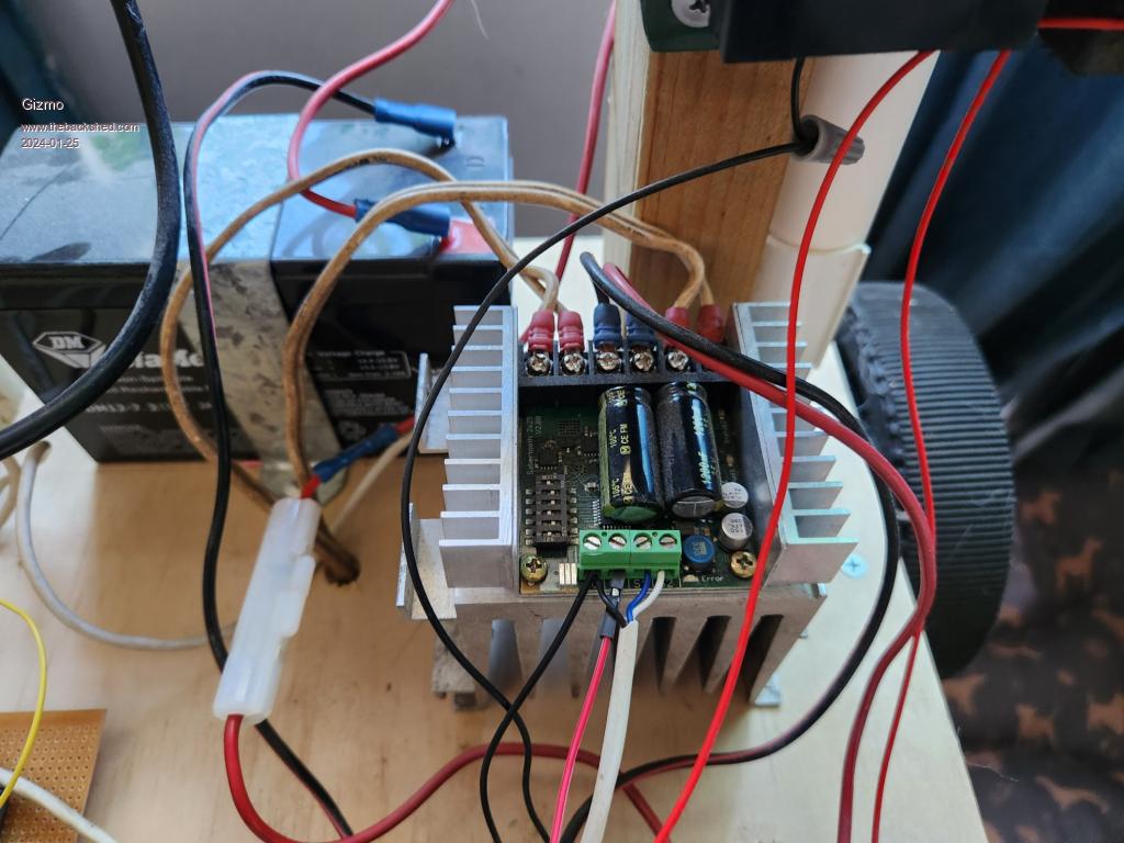 This was on my test rover. I did contact the manufacturer, they offered to fix it, but they are in the USA and it would take weeks. After doing some research, I've decided to build my own. Here is what it needs to do. Receive two RC signals from a flight computer. Drive two wheel motors. Its basically skid steer, the two wheels do the drive and steering, a caster wheel goes for the ride. I have a few spare ESP8266 D1 Mini modules, lets write some code, with a little assistance from ChatGPT. I find ChatGPT basically writes code that doesn't work most times, but it plants ideas in your head and gets you started in the right direction. To drive the motors I could use a H bridge, as each motor needs to go in forward and reverse. H bridges are a pain, you need high side drivers, and I wanted something I could throw together this weekend. The rover spends 99% of its time going forward, so I'll just use a PWM driven MOSFET output stage and a DPDT relay to reverse the motor when needed. Its simple. The code converts the RC signal into a pulse duration value, between about 1000 and 2000, where 1500 is center stick ( I called it dead stick in the code ). If the signal is above mid point ( plus a fudge factor ), the relay is off. If the stick is reversed ( < 1500 ) pull in the relay. The PWM is calculated with a little basic maths. #define PWM_INPUT_PIN 15 // Assuming you're using GPIO2 for PWM input #define PWM_OUTPUT_PIN 13 // Using GPIO0 for PWM output #define HIGH_LOW_PIN 12 volatile unsigned long lastRise = 0; volatile unsigned long pulseWidth = 0; float MidPoint = 1500; float DeadZone = 10; float MinPoint = 1000; float MaxPoint = 2000; float PWMSignal = 0; void ICACHE_RAM_ATTR handleInterrupt() { if (digitalRead(PWM_INPUT_PIN) == HIGH) { lastRise = micros(); } else { pulseWidth = micros() - lastRise; } } void setup() { pinMode(PWM_INPUT_PIN, INPUT); attachInterrupt(digitalPinToInterrupt(PWM_INPUT_PIN), handleInterrupt, CHANGE); pinMode(PWM_OUTPUT_PIN, OUTPUT); pinMode(HIGH_LOW_PIN, OUTPUT); Serial.begin(115200); } void loop() { if (pulseWidth > MidPoint-DeadZone && pulseWidth < MidPoint+DeadZone ){ PWMSignal=0; Serial.print("Dead Stick: "); Serial.println(); }else{ if (pulseWidth >= MidPoint+DeadZone) { PWMSignal=255 / (MaxPoint-MidPoint) * (pulseWidth-MidPoint); if(PWMSignal>255){PWMSignal=255;} Serial.print("PWM: "); Serial.println(PWMSignal); digitalWrite(HIGH_LOW_PIN, LOW); Serial.print("Relay On "); } else { PWMSignal=255 / (MidPoint-MinPoint) * ((MidPoint-pulseWidth)); if(PWMSignal>255){PWMSignal=255;} if(PWMSignal<0){PWMSignal=0;} Serial.print("PWM: "); Serial.println(PWMSignal); digitalWrite(HIGH_LOW_PIN, HIGH); Serial.print("Relay Off "); } } analogWrite(PWM_OUTPUT_PIN, PWMSignal); delay(200); } This code works great. Its only for one channel, I'll make changes to run both channels in the same board. The only issue I need to address is if the RC signal is lost, the motors should be shut off. I'll add that later. Next I'm building the relay driver and mosfet drive for the motors. More to follow this weekend. Glenn Footnote added 2024-01-25 16:58 by Gizmo I see the title of this post says Mome made, instead of Home made. Apparently a "mome" is a fool, a blockhead. I can live with that, been called worse. The best time to plant a tree was twenty years ago, the second best time is right now. JAQ |
||||
| Gizmo Admin Group Joined: 05/06/2004 Location: AustraliaPosts: 5185 |
Built the electronics into a old battery charger case. In hindsight, I wish I had used a bigger box, its a bit cramped in there. 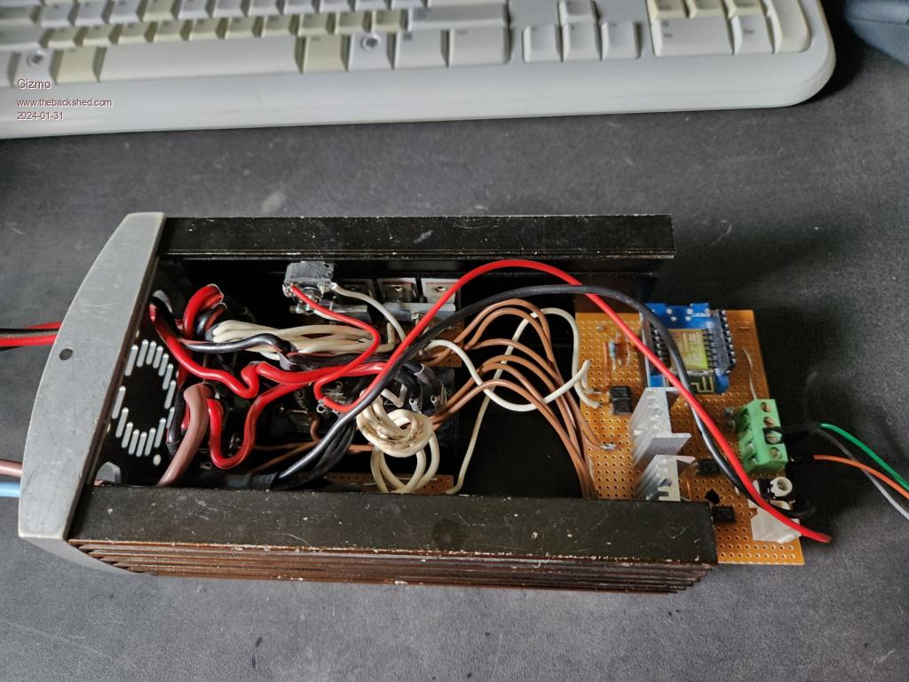 I'm using 4 MOSFETS in parallel for each channel, and 2 SPDT automotive relays per channel to do the motor reversing. I chose the auto relays because they are common and I can easily change the motor controller from 12V to 24V by wiring the coils in parallel or series. I've added a web interface to the controller, so it creates its own wifi hotspot and I can use my phone to open a web page and change the settings of the controller. I'm going to add a switch to enable this feature only when its needed, no need to broadcast a wifi signal when its not needed. More to come. Glenn The best time to plant a tree was twenty years ago, the second best time is right now. JAQ |
||||
Revlac Guru Joined: 31/12/2016 Location: AustraliaPosts: 1282 |
Looks good and should do the trick, The automotive relays should be fine, I had cooked relay on a thermo fan because the auto sparky hadn't crimped the terminal tight enough, not surprised I'm sure the legs on the relays are smaller than the old ones.  Cheers Aaron Off The Grid |
||||
| The Back Shed's forum code is written, and hosted, in Australia. | © JAQ Software 2026 |
