
|
|
Forum Index : Electronics : Builiding of a complete 6kW PV inverter with MPPT chargers
| Author | Message | ||||
| -dex- Senior Member Joined: 11/01/2024 Location: PolandPosts: 101 |
If you look at it this way, it is actually 11T on CT. In the case of a choke, the excess can be easily rolled away. |
||||
| -dex- Senior Member Joined: 11/01/2024 Location: PolandPosts: 101 |
It's been a while since I posted anything in the thread about the construction of my inverter. Recently I have been doing something else, and the description of the structure is late compared to the current state. I will come back to the battery and BMS. I've previously written about the terrible lifepo4 startup failure and battery explosion. This made me afraid to touch the cells any further, everything was dismantled and put back in cardboard boxes. I discovered that the short circuit was caused by incorrect compression, which resulted in damage to the blue insulation which short to the inverter casing. There were also no spacers between the cells and no BMS protection. When the dust settled, I ordered some new cells - I actually have to buy them in multiples of 4, that's how they come in packs of 4 and Chinese sellers don't sell one. I put together a package of 16 cells again. I measured each cell's internal resistance, which is extremely low. Even the one that was damaged (go back to previous posts - melted battery terminal, damaged casing, electrolyte leak) had the same resistance and voltage as the other cells  !!! But I replaced it with a new cell anyway. !!! But I replaced it with a new cell anyway.This time, everything is insulated: the bottom on which the cells sits, the sides of the pack, and each cell are separated with 1.5 mm thick plexiglass. This time I don't use any compression. The reason for the lack of compression will be discussed later. I added further layers of protection: BMS with overcurrent protection for charging and discharging, voltage control and each cell separately, and an active 2A balancer. Moreover, in the middle of the series I placed an additional fuse with a value of 120A - if there was a short circuit at the battery terminal itself, it would burn out. The BMS is configured via a smartphone application and connects via Bluetooth. It also has wired communication, which I would like to use in the future to present battery data, mainly battery's SoC, in my building automation system. I also have a large touchscreen display for it, placed next to the other LCD displays. In the last photo you can see the resistance of the entire package thus cells and all connections between them, which is measured at the + and - output of the 51V battery. When you do the math, you'll see what a brutal force can it be  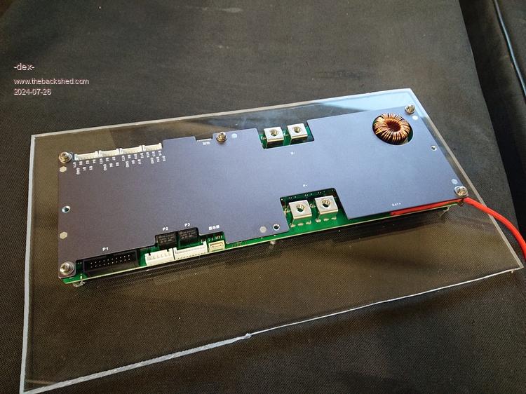 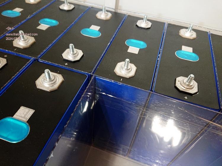 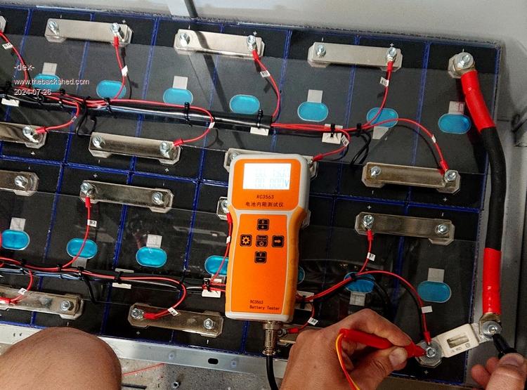 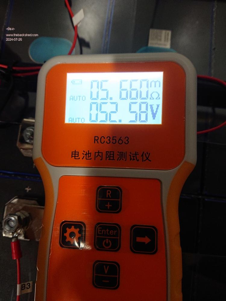 Edited 2024-07-26 22:57 by -dex- |
||||
| -dex- Senior Member Joined: 11/01/2024 Location: PolandPosts: 101 |
Oh, I just realized how bad a some photos are. Sorry, I'm neither a good photographer nor a reporter  In the photo where you can see the resistance meter and the battery pack, the resistance of the fuse is measured. This is not a test involving short-circuiting the battery with a cable and a fuse!!!!!! In the last photo I am measuring at the battery output terminals, on the other side of the battery pack, which is not included in the photo. Edited 2024-07-26 23:09 by -dex- |
||||
| KeepIS Guru Joined: 13/10/2014 Location: AustraliaPosts: 1873 |
Great news on pack, fortunately mine came with fiberglass separator sheets, but what you have is great. The BMS should also help indicate if any terminal resistance loss creeps in under high loads over time. I normally check the battery pack link bars with a resistive load of around 50A to verify each cell link, and recheck them a few times as the pack settles in. I like the internal-R test Meter  NANO Inverter: Full download - Only Hex Ver 8.1Ks |
||||
| KeepIS Guru Joined: 13/10/2014 Location: AustraliaPosts: 1873 |
FYI: Uploaded V7.3 with adjustable timed delay of restart ramp-up after a Low-Battery stop condition, see included "Latest changes.txt". Download NANO Inverter: Full download - Only Hex Ver 8.1Ks |
||||
| -dex- Senior Member Joined: 11/01/2024 Location: PolandPosts: 101 |
The system constantly supplies almost the entire house with electricity (only the 3-phase heat pump is connected to the grid), continuously and without any failures for several weeks. I would like to thank everyone for their help, especially wiseguy KeepIS poida and many others, thank you! Time for some photos, I've never shown what the whole thing looks like, I'll do it now. 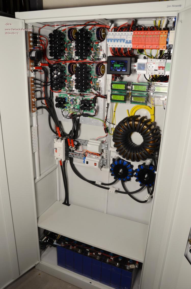 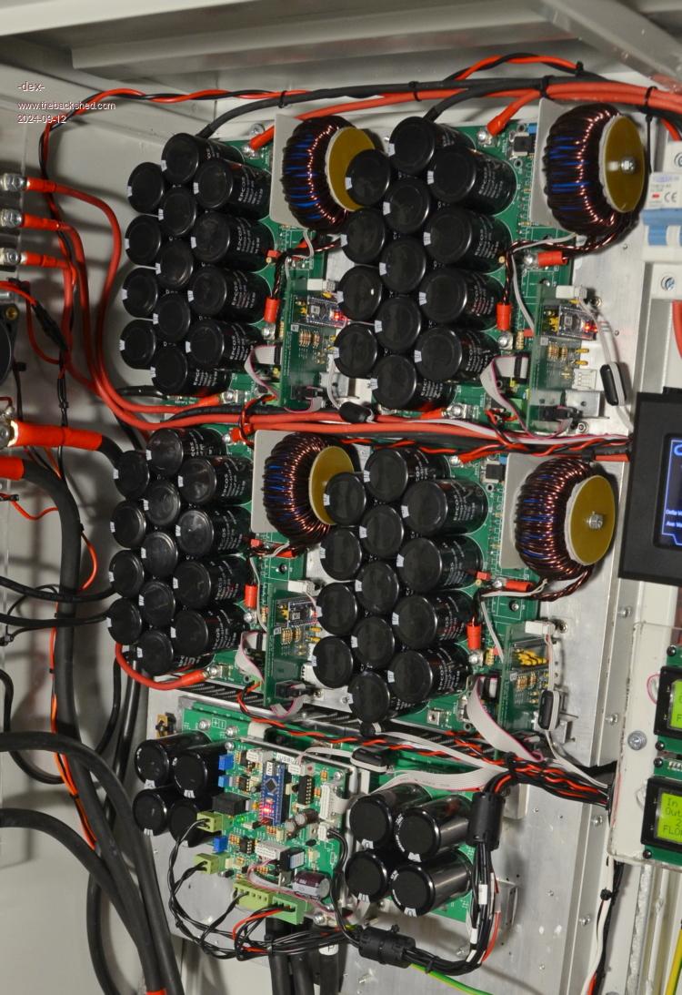 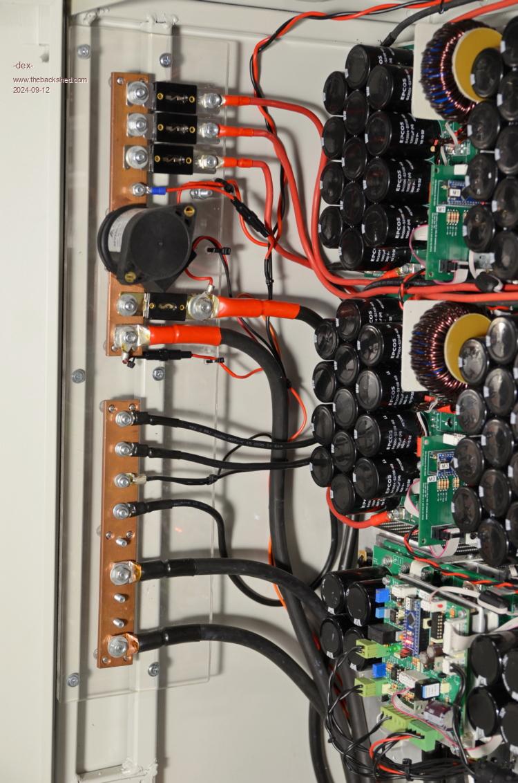 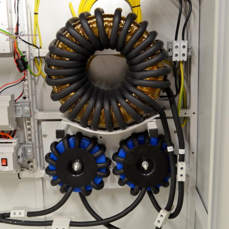 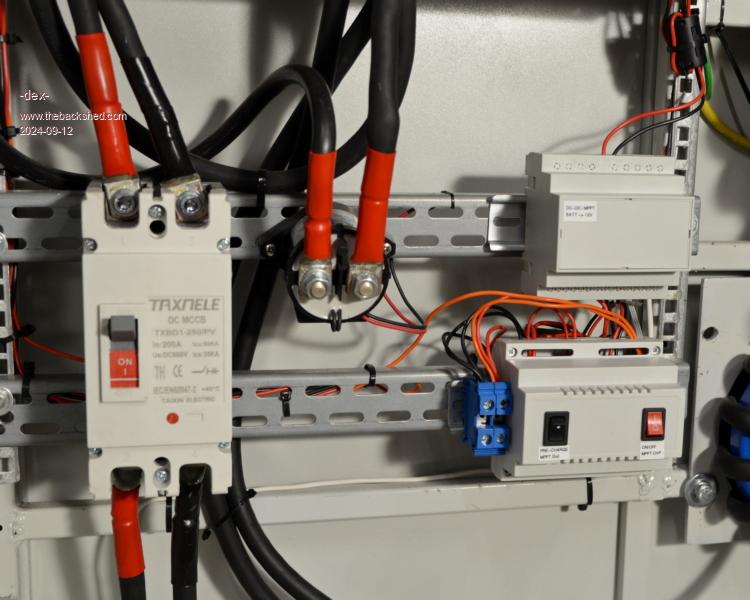 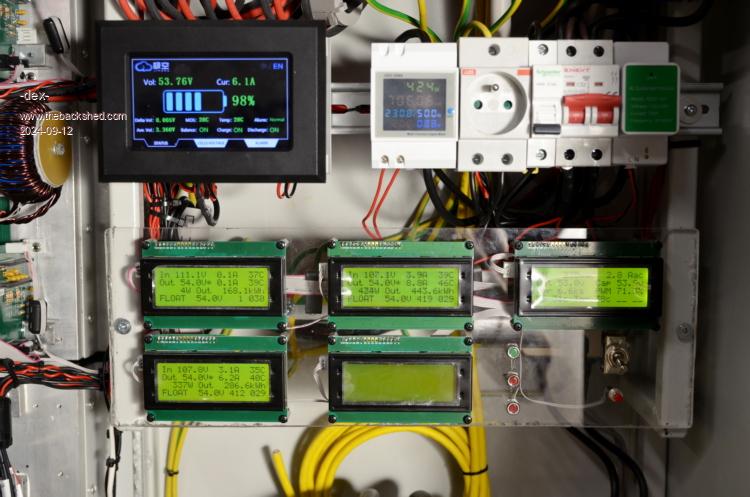 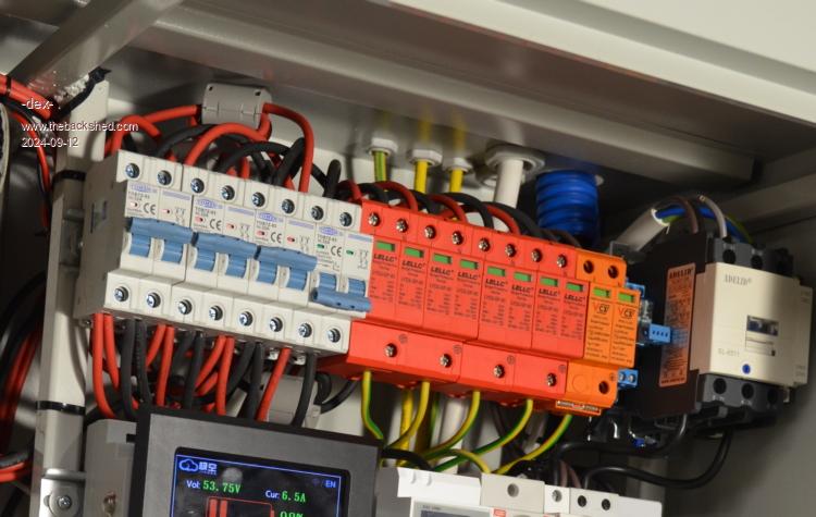 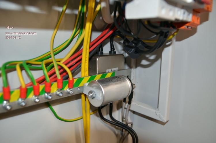 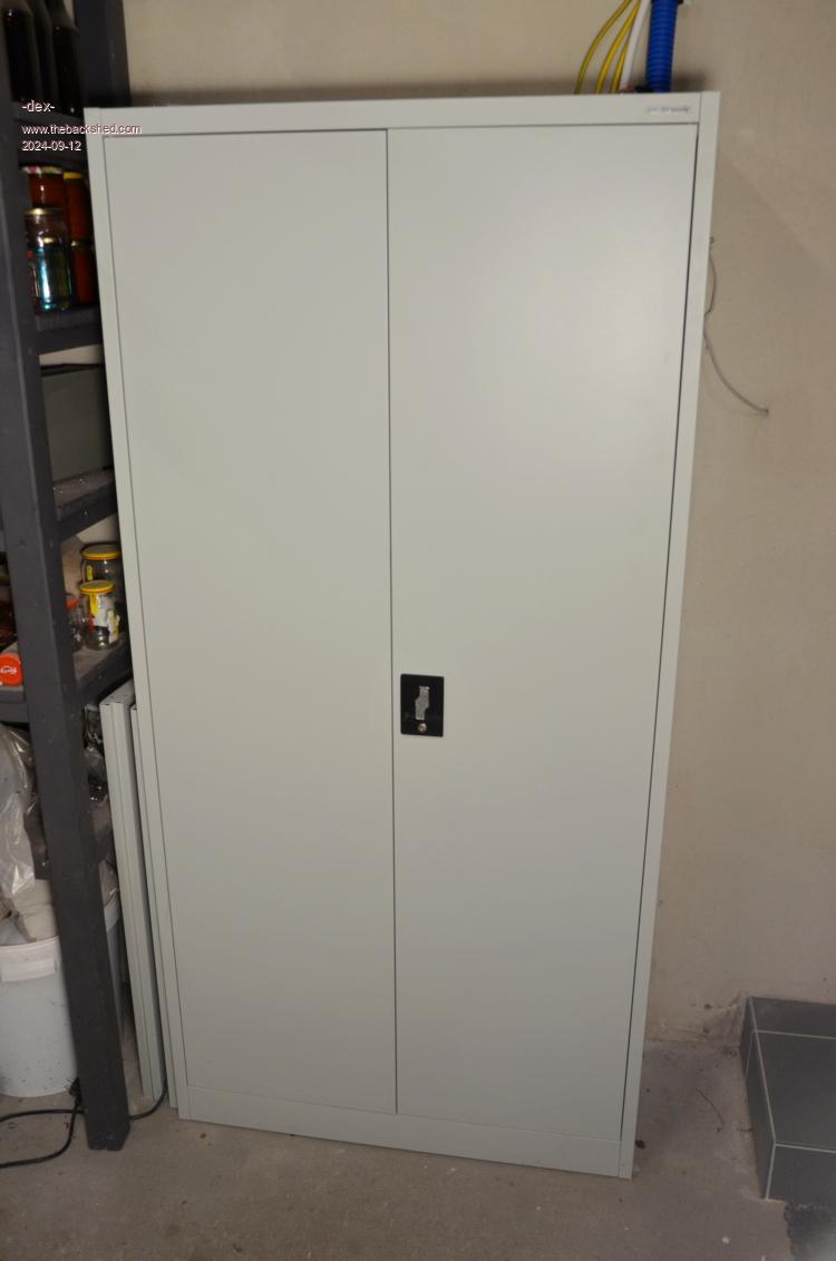 Edited 2024-09-12 02:22 by -dex- |
||||
| KeepIS Guru Joined: 13/10/2014 Location: AustraliaPosts: 1873 |
An absolute work of ART - Where did you purchase it - It must have cost a fortune Congratulations for the time and effort that went into that   _ NANO Inverter: Full download - Only Hex Ver 8.1Ks |
||||
Revlac Guru Joined: 31/12/2016 Location: AustraliaPosts: 1153 |
Defiantly a work of art, so would be the wiring diagram  Very nice, there is a lot of work there. I'm also doing a cabinet with everything inside, batteries at the bottom etc, but 230vac will go to the main box on the side of the house to a generator input and changeover switch. Cheers Aaron Off The Grid |
||||
| -dex- Senior Member Joined: 11/01/2024 Location: PolandPosts: 101 |
I have already written about the cabinet here: In fact, it is a housing for office binders, appropriately adapted. I like this style of industrial electronics, of course there are ready-made telecommunications cabintes, but new ones cost as much as a factory build inverter  The office paper cabinet cost a fraction of the price but required welded reinforcements and something to mount electronics to. I did all this myself with an electrode welder, I'm a beginner welder, but these welds were not demanding. The paint covered any possible imperfections Originally, there were supposed to be 3 shelves at the bottom of the cabinet for three sets of batteries, then I reduced it to 2 shelves, and finally stopped at 1 shelf. Now, when I think about adding more batteries, I want to place all the cells in a separate housing nearby. The problem is that I have room for another cabinet at a distance of about 8-10 m from the inverter = lots of long and thick battery cable. If I move these blue cells to another housing, I will gain additional space, which I will probably spend on a transformer charging the batteries at a cheap night tariff - only in winter when there is no sun here. I have the E-shaped transformer shown at the beginning of the topic. Every time I open the cabinet's door I feel warm. While this does not have a significant impact on electronics, batteries do not like excessive heat, because heat accelerates the aging process. There may be a good reason to mount them separately. It's true that my batteries are decoupled and they are at the bottom, and the warm air always rises to the top. I'll borrow a thermal imaging camera and check the heat distribution! Edited 2024-09-12 17:53 by -dex- |
||||
| KeepIS Guru Joined: 13/10/2014 Location: AustraliaPosts: 1873 |
Hi -dex-, yes I saw your initial post on the cabinet, I was being "tongue in cheek" and it likely got lost in translation I meant that the total package and build looked like a quality commercial device and installation, really - really nice. NANO Inverter: Full download - Only Hex Ver 8.1Ks |
||||
| wiseguy Guru Joined: 21/06/2018 Location: AustraliaPosts: 1206 |
Dex that is truly an amazing build one of the neatest and easiest to work on I have ever seen. Quality & neatness of wiring etc is first class and has set a standard that I (we?) would all aspire to achieve. You can feel justifiably proud of your achievement. How many friends and neighbors have suggested they would like one too Did you manage to tame the inverter noise so you could use your amateur radio gear whilst the inverter is on, or is it still too annoying? What circuitry is hiding in the little plastic boxes just to the left hand side of the 2 x chokes ? I hope it continues to gives you good performance and service for a very long time. If at first you dont succeed, I suggest you avoid sky diving.... Cheers Mike |
||||
| Revlac Guru Joined: 31/12/2016 Location: AustraliaPosts: 1153 |
I did start off with a separate battery box, its been ok but can get a bit cold in the winter been outside, the reason for me trying to have it all in the one place was to help keep a fairly stable temp overall and very short battery cables, the batteries have a fair bit of thermal mass due to there size, will see how it works later or If it needs to be changed it has air vets and a fan when needed, I have room under the cabinet to put batteries. There are few commercial offgrid units made with everything in the one box or crate outdoors. Cheers Aaron Off The Grid |
||||
| -dex- Senior Member Joined: 11/01/2024 Location: PolandPosts: 101 |
Thank you for your kind words. From the beginning, I treated the project very seriously because I put a lot of effort, money, my time and your commitment into it. There's something about it that makes me want more, do you have that too? Now the idea of building another inverter - a reserve one, or a "summer" inverter to power the air conditioning - is slowly blooming in my head. This time I will approach the topic more relaxedly. These small casings are described, but the camera operator failed to focus 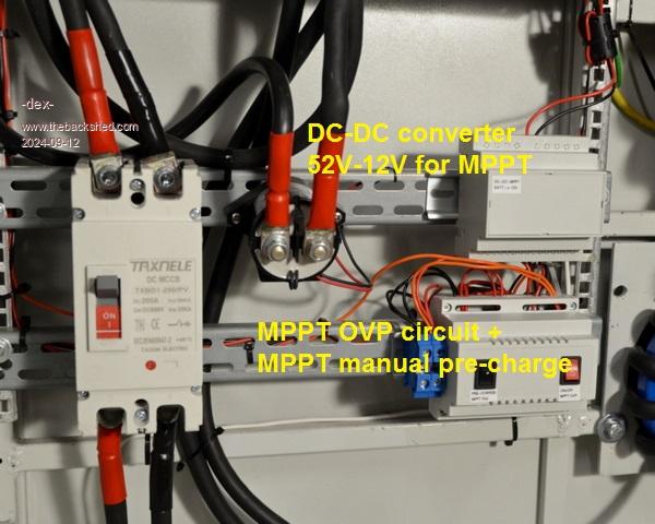 There is also a third housing, hidden under the battery BMS display. There is a BMS module start-up switch on it, and an additional fuse box set for 12V inside. 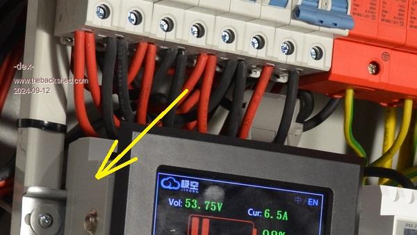 The radio noise is still there. I'm usually on the radio in the evenings, then I disconnect the PV thong by the breaker. Ferrite rings on the cables do not solve the problem. I would like to use full-fledged EMI filters on the MPPT inputs, I will look for new ones or build my own. Now what I'm going to say will sound strange, because it contradicts what I said earlier. At first I assumed they could be there together because it's cold there in the winter, so I hoped the others would warm it up a bit. Lifepo4 does not like to be charged at low temperatures. Now that it's all in place, I can take measurements and make a final decision. |
||||
| The Back Shed's forum code is written, and hosted, in Australia. | © JAQ Software 2025 |
