Notice. New forum software under development. It's going to miss a few functions and look a bit ugly for a while, but I'm working on it full time now as the old forum was too unstable. Couple days, all good. If you notice any issues, please contact me.
Murphy's friend Guru Joined: 04/10/2019 Location: AustraliaPosts: 678
Posted: 08:02am 17 Mar 2024
Copy link to clipboard
Print this post
Quite a bit of inverter building has been posted about here lately so I'll add my 2 cents worth .
I was facing a stack of parts removed from my jinxed warpinverter and thought I could build an inverter or two from these.
It is a very basic (no bells & whistles) EG 8010 based design, since I still have a few of those chips from my early inverter building days.
I do like the power PCB on heatsink approach Mike posted about but add my own bag of tricks.
A big expense of a decent size inverter is that large 2oz copper PCB for the mosfets & capacitors.
So, if I told you that I just built a 6KW inverter using 1oz PCB board for the mosfets you possibly won't believe that.
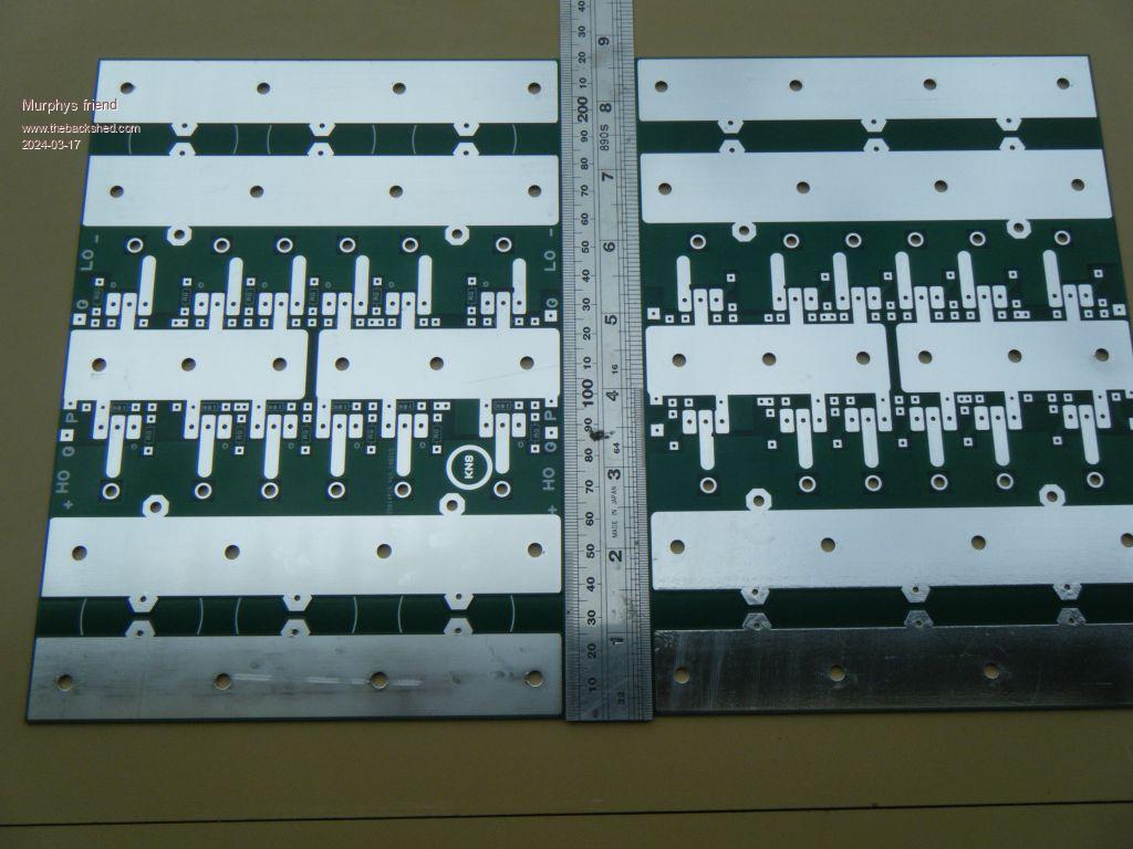
But, with the right track layout, making the top & bottom power tracks identical, one creates 2oz copper tracks by paralleling those tracks. This has the added advantage of these tracks having now twice the surface area for even higher current capacity.
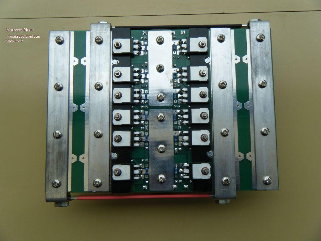
So, here is what this power PCB looks like for 12 HY5608 mosfets:
The top and bottom side are shown next to each other.
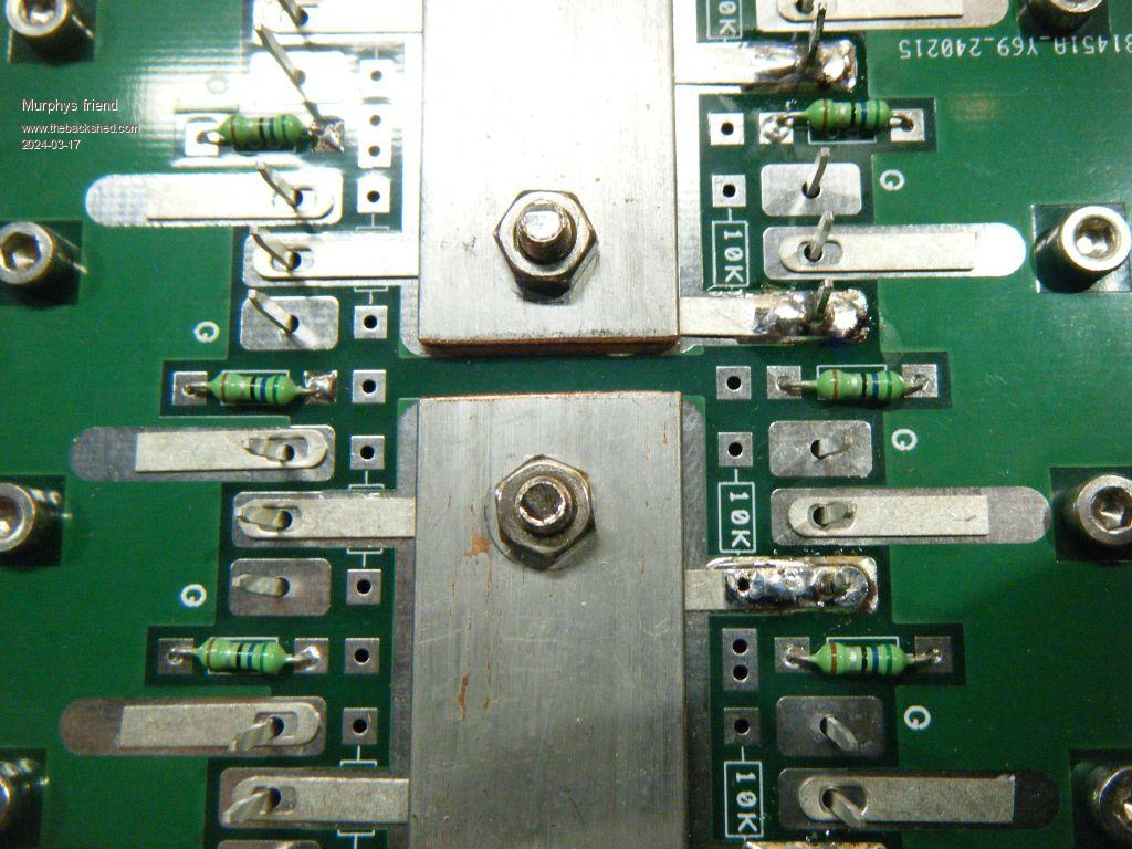
Ther is still the track bottle neck where it narrows to connect the mosfet pins to take care of. For this I use warpspeeds trick of cutting the tail off long tail solder lugs. The next picture shows that arrangement. Anybody considering this, make sure they are tin plated *copper* lugs (dull silvery finish) and not nickel plated brass (shiny finish) which is useless for this application.
A tip about soldering these lug tails: I have 2 sets of 60 W temperature controlled soldering irons and neither of them was up to the job with the biggest tip available. There is simply not enough heat storing capacity in those thin walled 6mm tips those irons usually come with.
I use an old fashioned non temp controlled 80W iron with a decent 10mm copper rod wedge tip. So, if it takes you longer than 2 seconds to fully flow the solder around the mosfet pins & solder lug, a more suitable soldering iron is recommended.
The next picture shows my power connections to the PCB tracks. I am not a fan of those dainty 6 legged, solder on PCB, screw connectors. They make it too difficult to route 32mm sq power cable & lugs to, this is much easier off the board where I can use 8mm bolts to make that connection.
Another thing you'll notice is the complete absence of the driver components, I find they clutter up space there and make the board bigger than it needs to be. It's, IMO, much easier to use a piggy back PCB for that which can have equally short gate tracks. The only small parts on that power PCB are the gate & source/gate resistors.
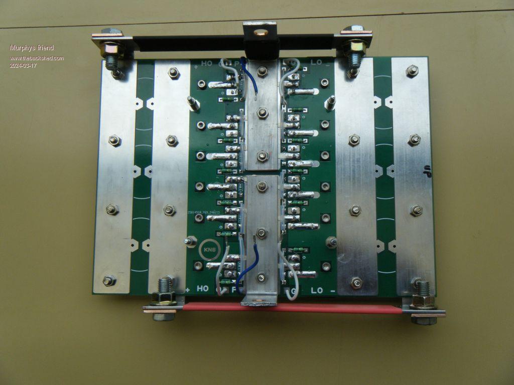
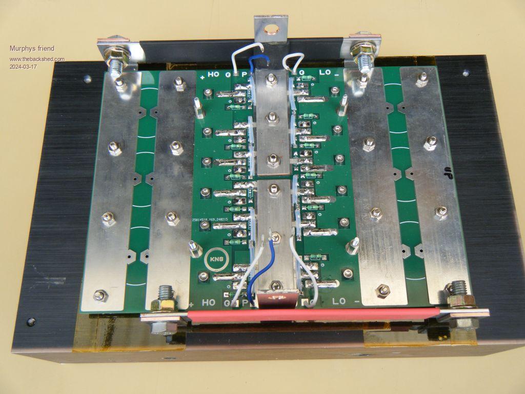
The following is a picture of the bottom side of the assembled power board. Note, there are no fancy mosfet leg gymnastics required to accommodate the ferrite beads. Just bend the legs at a right angle where their size reduces.
You may not see it clearly (its black) but I placed the mosfets on a 3mm thick fibreglass board spacer strip, between the mosfet top and PCB, to increase the gap between the heatsink & board to 6 mm. This also gives me clearance for the copper busbars (20x2mm) plus better air circulation under that board.
I designed that board for an Aerosharp heat sink but then realised I had an equally suitable heatsink from an old GTI which had a thick side fin, making it very easy to mount it with 2 x 8mm bolts in my inverter case.
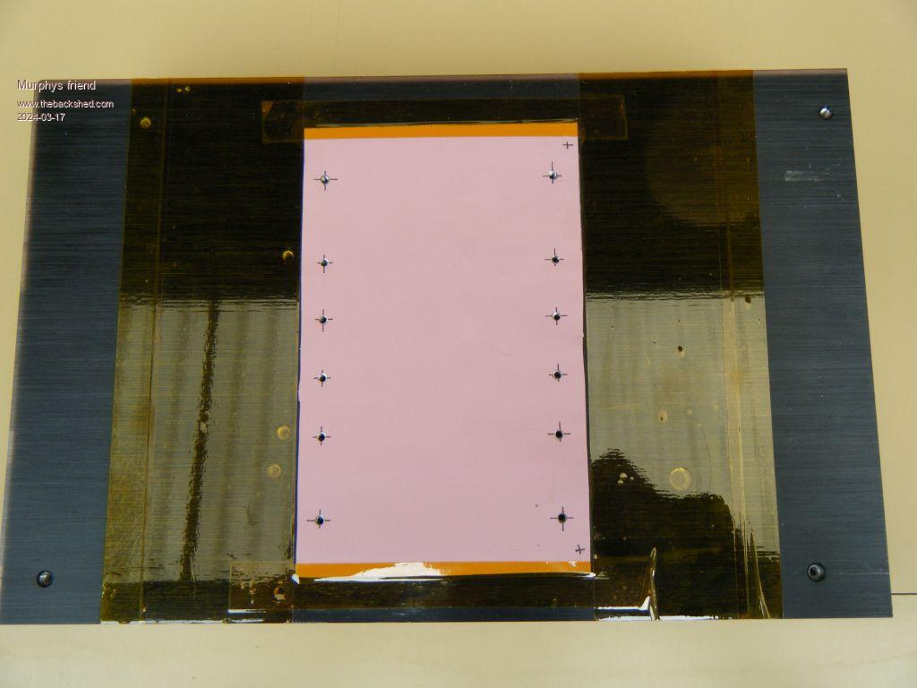
The heat sink uses a silicone sheet to isolate the mosfet drains, this is taped in place with Klapton tape. This is much easier than using individual mosfet insulators which would be difficult to keep aligned when the board is mounted onto the heat sink.
To be continued
Murphy's friend Guru Joined: 04/10/2019 Location: AustraliaPosts: 678
Posted: 08:36am 17 Mar 2024
Copy link to clipboard
Print this post
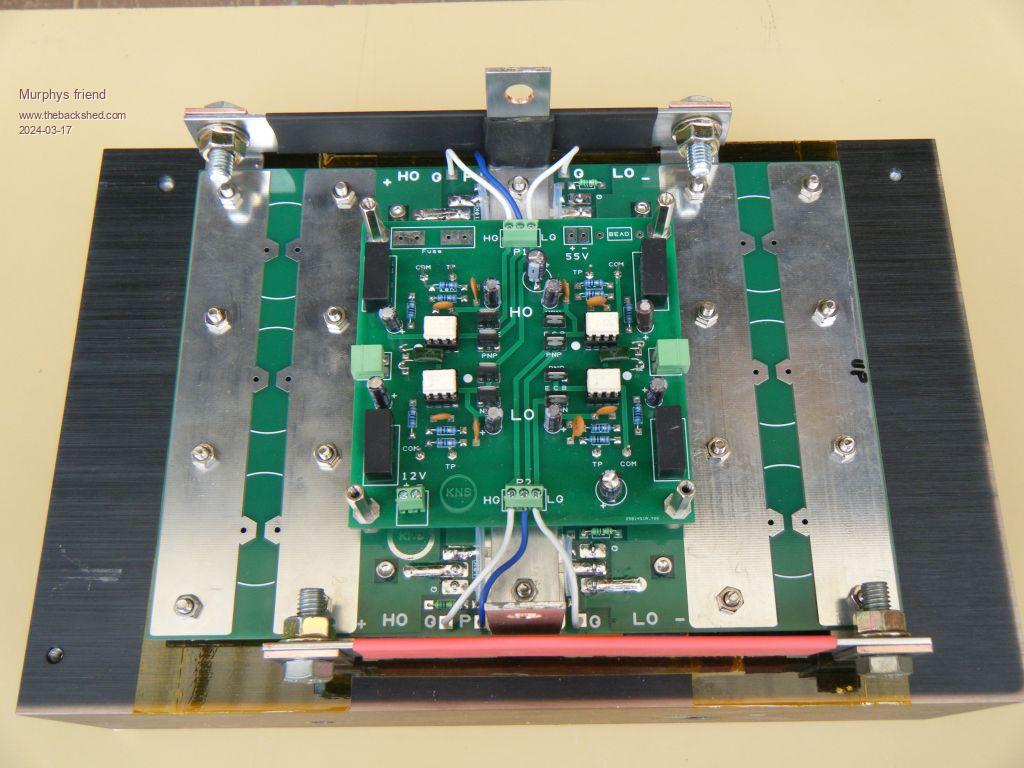
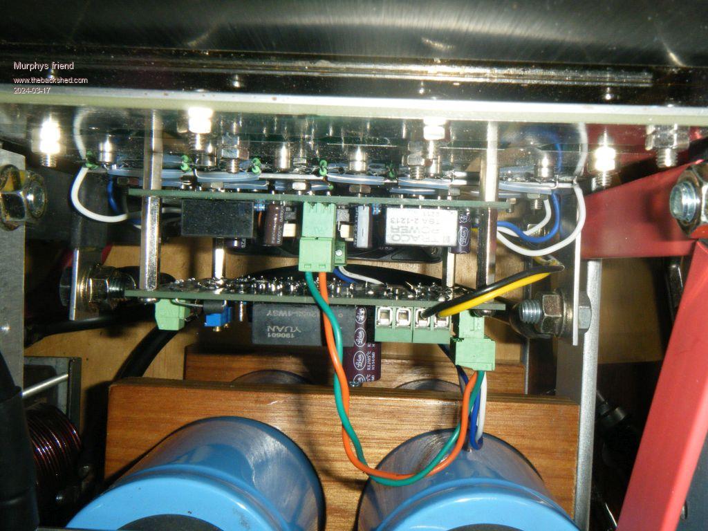
Next is a picture of the power board mounted onto the heat sink.
There are no capacitors fitted to the board as I'm re cycling the big (and expensive)33000uF/100V caps from that warpverter. These are mounted just next to the board.
Also, note the metal spacers for the 100x100mm piggy back boards. 2 of them connect the battery voltage up to the control board for voltage monitoring.
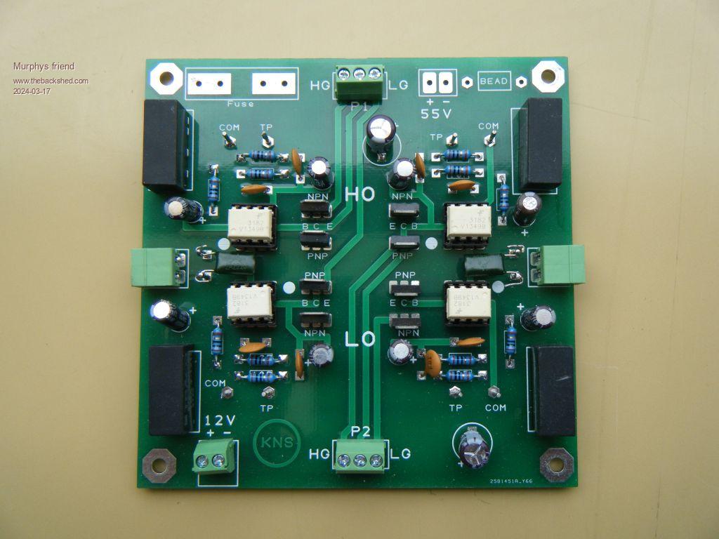
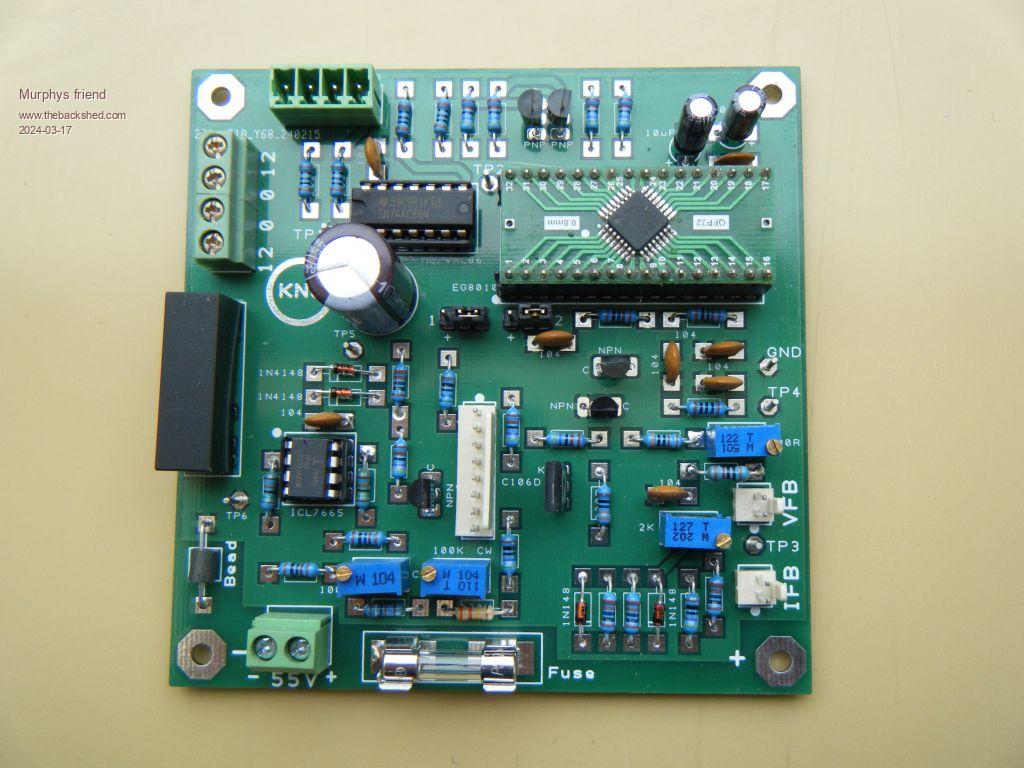
The first piggy back board holds the drivers. it looks like this:
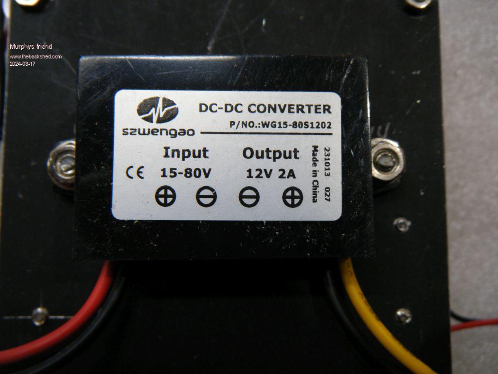
I'm using a different method to get the isolated 15V supply for the drivers. First the battery voltage is reduced to 12 V using one of these:
This also supplies sufficient power for the 120mm 12V/10W fan.
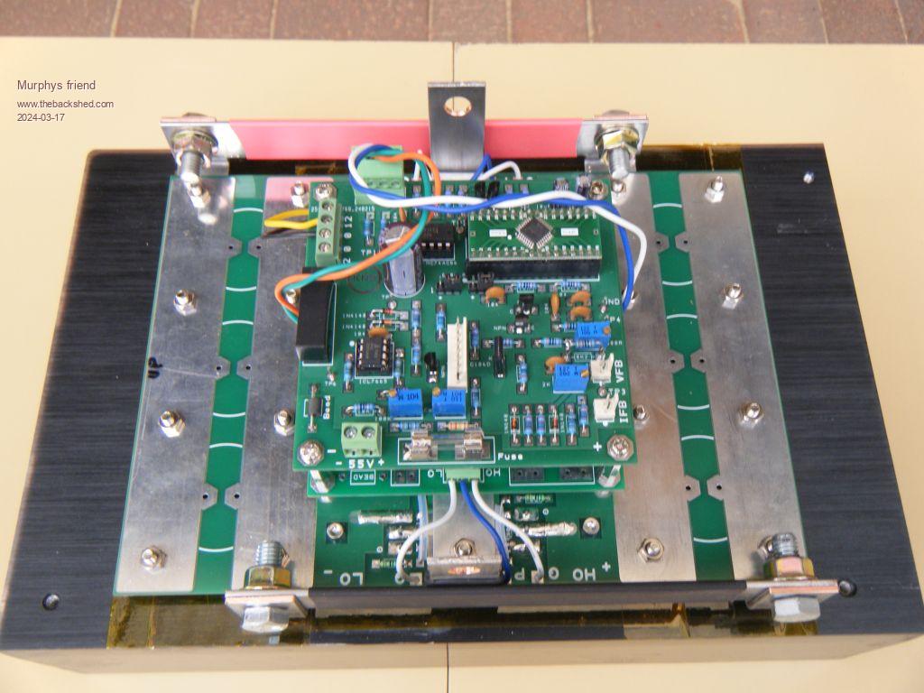
Here is the driver board piggy backed on the power PCB:
There are 4 off, 12V to 15 V, isolated boost modules on that board for the FOD3182 drivers.
The top piggy back PCB is the control board. Just a simple EG8010 chip with wiseguy's balanced output modification.
Battery low voltage shut down (or start up) and over current shut down installed. Both use a crow bar method to turn the EG8010 off. Current monitoring is via a current transformer independent from the EG8010. There is no EG8010 fan control (I use an external temp. monitor with a display).
As you see, no bells & whistles .
To be continued.
Murphy's friend Guru Joined: 04/10/2019 Location: AustraliaPosts: 678
Posted: 10:41am 17 Mar 2024
Copy link to clipboard
Print this post
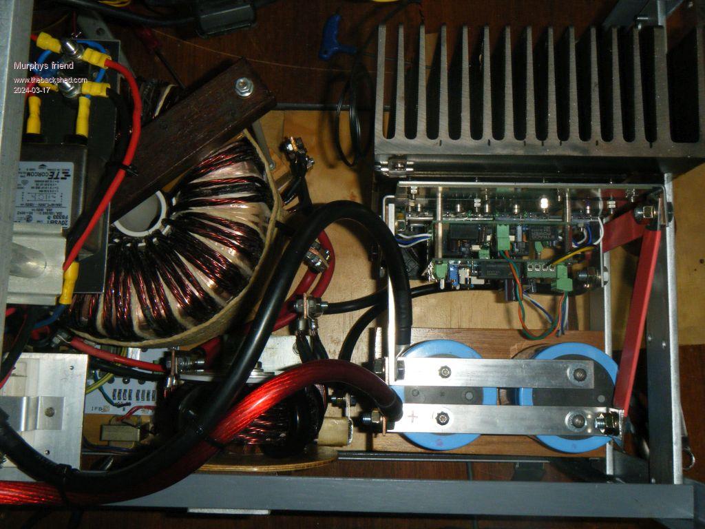
Here is the complete electronics mounted on the heat sink:
This arrangement makes it very handy for setting up the trim pots and testing on the bench top. Even later, for trouble shooting, it can be removed from the cabinet as a unit after disconnecting the power and undoing the 2 bolts holding the heatsink in place.
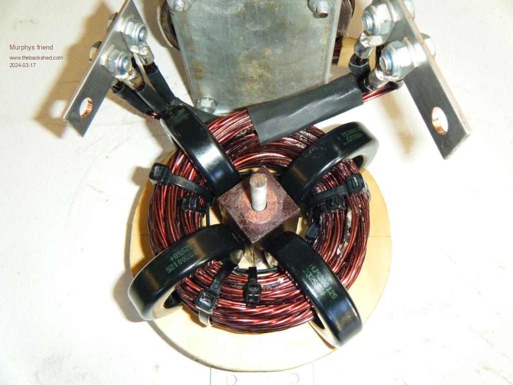
Next, one of the 2 chokes I used:
My thanks go to the person who posted a picture of arranging the toroid rings this way. It makes the coil insertion sooo much easier. I just pre wound each of the 4 x 5 turn coils on a suitable PVC pipe section and then inserted them, corkscrew fashion, one at a time. Definitely beats trying to get that wire through a stack of 4 cores.
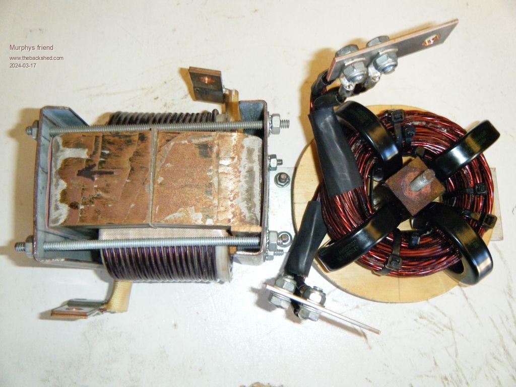
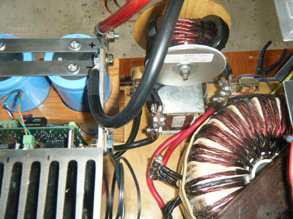
The other choke is a silicon steel version I had made for the warpverter. It had a wedge shaped gap but that proved to be noisy so now it's replaced by a 1.9mm gap.
But that choke gets too hot for my liking at high power so I will replace it eventually with another ring core job like the one above. Perhaps even a 6 core version, should be easy enough to make.
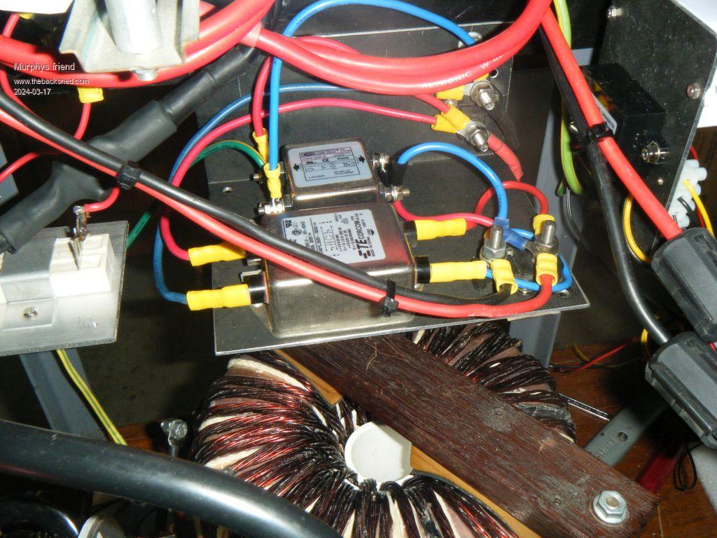
Now some pictures of the rest of the build:
This inverter is going to be work in progress for a while, it will only be yet another spare once I finish tinkering with it.
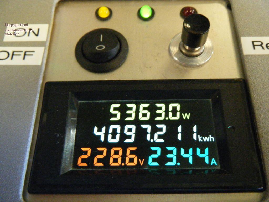
So far I ran it up to 5KW, could not find any more handy plug in loads.
The sine wave looks nice up to 3KW, after that the side slopes straighten with a tighter to & bottom curve. The microwave still puts some kinks into the slopes but not objectionably so.
Godoh Guru Joined: 26/09/2020 Location: AustraliaPosts: 675
Posted: 08:47pm 17 Mar 2024
Copy link to clipboard
Print this post
Looks fantastic, very nice looking inverter. It looks like you have put in a huge amount of work to build that one from scratch. Pete
Murphy's friend Guru Joined: 04/10/2019 Location: AustraliaPosts: 678
Posted: 03:39am 18 Mar 2024
Copy link to clipboard
Print this post
Thanks Pete. It's not my first inverter build BTW, more like a hobby gone addictive . Got to keep busy doing something I enjoy doing in my retirement years.
rogerdw Guru Joined: 22/10/2019 Location: AustraliaPosts: 955
Posted: 12:51pm 18 Mar 2024
Copy link to clipboard
Print this post
That looks very impressive Klaus, lots of thought and work has gone into that. Nice and clean and open.
Seems that inverter building is addictive all right, but I guess we could have worse vices. I'm still on number one and I suppose a backup is probably a wise investment ... but I'll wait until my system is completed before I start exploring my options.
I know I built my bridges on modules ... for ease of swapping out if one fails ... and so I didn't have to risk tapping all the holes on just one heatsink ... but if I was to repeat the process, I think I would take that risk and do what you and the two Mikes have done.
My circuit board layout experience is very limited, but I don't mind the extra expense of the 2oz copper. I see it as insurance ... and as long as there's no mistakes with the board and it has to be redone ... it's really just a one off expense that helps with the overall strength and reliability of the unit.
I'm sure if I was going into mass production and it had to be a money making venture then things might be different. And it's not that I'm made of money, it's just that I see value in good solid copper tracks where needed ... especially after working for years on boards and dreading the ones that are flimsy and likely to fall apart if needing heavy rework. I have certainly saved heaps by using a lot of secondhand stuff in my builds where it's not quite as important.
I will follow with interest to see how this one performs. Very inspiring.Cheers, Roger
Murphy's friend Guru Joined: 04/10/2019 Location: AustraliaPosts: 678
Posted: 01:51pm 18 Mar 2024
Copy link to clipboard
Print this post
Thanks for your kind words Roger, I appreciate them.
The "solid 2oz copper" on my power board is also present in the form of two 1oz tracks in parallel, plus the additional brute capacity of the copper busbars. It's just a different way to achieve high current capacity.
BTW, the price of the 3 PCB's on that heatsink, including delivery (by the cheapest option), comes to the grand total of twelve dollars . One has to include the price for the copper bars in the total board cost of course but I do like the M8 bolt connecting advantage they give me.
You may have noted that I don't use small pads for the components nor the tiny tracks one sees on commercial boards. That makes repair or parts changing easy without worrying of track lift off, something you would appreciate as a PCB repair man.
Godoh Guru Joined: 26/09/2020 Location: AustraliaPosts: 675
Posted: 08:20pm 18 Mar 2024
Copy link to clipboard
Print this post
Mr Murphy, it is fairly obvious that you this is not your first project or inverter, it is lovely work. As far as circuit boards go, I am in the process of trying to adapt an EV charger to give me more control over the current output. The board has lots of miniscule tracks. I really don't like surface mount stuff at all. I think your boards look great, through hole boards are the best option in my world. I really don't get the need to minituarise everything. Coming from an electrical / electronics repair background, I like stuff to be open easy to get at and repairable. Pete
nickskethisniks Guru Joined: 17/10/2017 Location: BelgiumPosts: 481
Posted: 08:32pm 18 Mar 2024
Copy link to clipboard
Print this post
I'm really amazed by the craftsmanship lately, this one is again a piece of art to be put in the hallway with a piece off plexy as a cover, will be a real shame to put it behind metal covers.
If I may, I find it a clever way to use the cores like you did and I saw it also in the other thread. I would keep an eye on the inductor cores while testing, it crossed my mind now, but I ones read a datasheet of iron powdered cores and they suggest to spread the windings evenly around the surface of the core. There may be a higher concentration of magnetic flux in certain regions of the core. This can lead to increased core losses due to higher magnetic flux densities, which in turn can reduce the efficiency. Maybe some local saturation which will increase the local temperature. With powdered cores it will degrade the material faster. Sendust cores don't have organic material in them so I don't know.
I see you don't populate capacitors on the pcb itself? Personally I like some small low esr/esl capacitors as close as possible to the mosfets. I see some room and solder able holes between those massive bus bars. Edited 2024-03-19 06:34 by nickskethisniks
Murphy's friend Guru Joined: 04/10/2019 Location: AustraliaPosts: 678
Posted: 01:17pm 19 Mar 2024
Copy link to clipboard
Print this post
Thank you for your kind words. No plexiglass covers and no hallway location for that one, I made it for use not just looking at it .
Your choke core comment is noted, if you look at one of the pictures you'll see the windings just about completely fill the toroid hole so, would that not suggest they are spread evenly around the (inner) surface? That choke does not even get warm with 5KW of load but the choke next to it (silicon steel core) does get uncomfortably hot. I will replace that with ring cores when they arrive.
The holes between the busbars are indeed for 6 capacitors (3 each side). I could easily solder some there but do not presently have suitable sized ones available. Hence the use of the massive 2 x 33000uF caps a short distance away, connected by 40 mm sq busbars.
oreo Senior Member Joined: 11/12/2020 Location: CanadaPosts: 133
Posted: 03:28am 20 Mar 2024
Copy link to clipboard
Print this post
I think I have looked at these photo's at least 10 times already, because your build looks so neat and tidy. Looks like an OEM piece except of course the wood.
I see your efficiency numbers and am wondering approximately how much output you get with continuous duty at say 70F room temperature?Greg
Murphy's friend Guru Joined: 04/10/2019 Location: AustraliaPosts: 678
Posted: 12:54pm 20 Mar 2024
Copy link to clipboard
Print this post
Thanks Greg. This inverter has just been completed and is presently used for tinkering, not for continuous output. So, I cannot answer your question.
Revlac Guru Joined: 31/12/2016 Location: AustraliaPosts: 1282
Posted: 09:27am 22 Mar 2024
Copy link to clipboard
Print this post
That turned out very nice, good to purpose parts and have it all work. The efficiency at low power is great. Cheers Aaron Off The Grid
Murphy's friend Guru Joined: 04/10/2019 Location: AustraliaPosts: 678
Posted: 07:58am 07 Apr 2024
Copy link to clipboard
Print this post
Time for an update about my inverter tinkering.
I was interested in how to minimise standby loads (a load that the inverter draws from the battery 24/7 when it is not powering anything plugged into it. These loads are comprised of the magnetising power the core requires and what the electronics of the inverter consume to make it generate AC.
Magnetising losses can be minimised by winding the transformer to a 1 Tesla flux density. The remaining losses can be reduced by selecting a suitable choke for the primary circuit. This is what I did today, here is a list of the DC input power (at 55V DC) consumed from the battery with no external AC load:
I experimented with higher inductance chokes as well but the idle power reduction was marginal and not worth the extra copper losses.
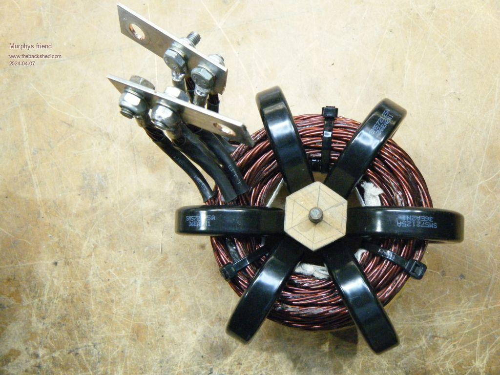
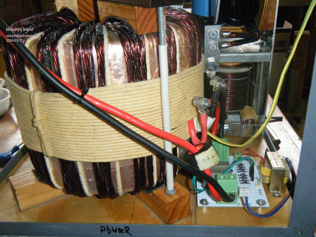
The 39W load above had a choke in each leg of the primary. One was a 6 ring Sendust core choke like this:
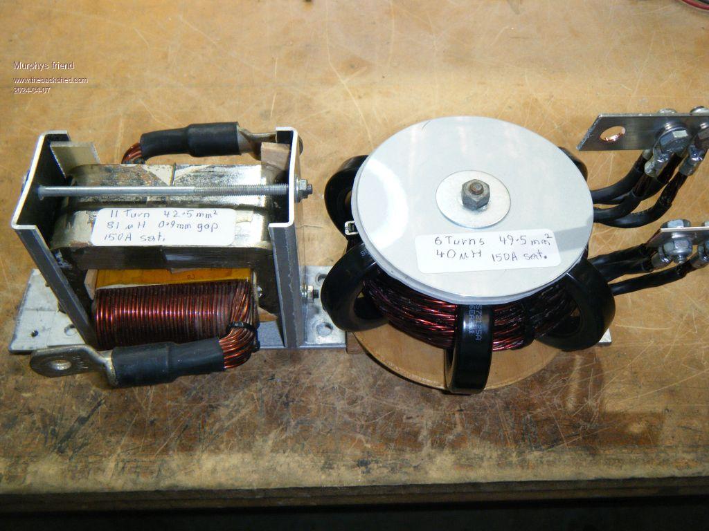
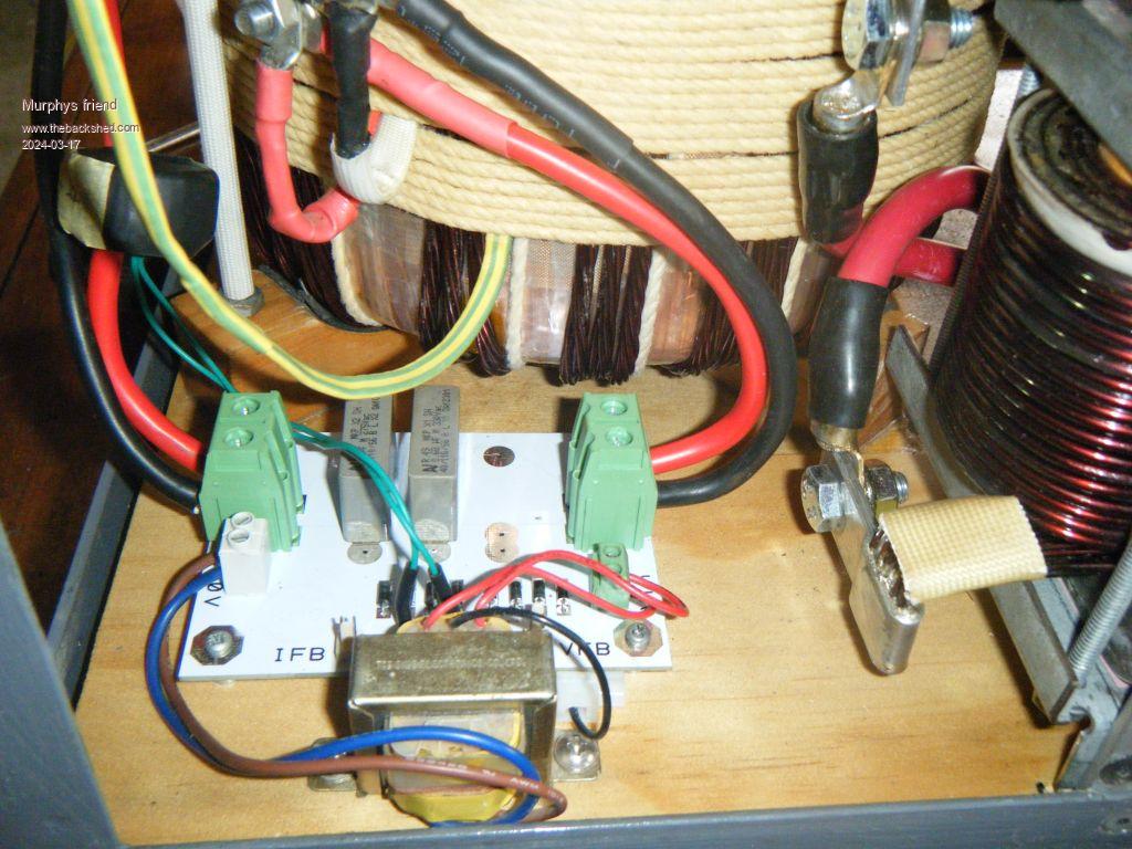
The other choke was made from a re cycled Aerosharp C core. Here is a picture of both chokes:
Considering that my 3KW inverter has a standby power of just under 20 W then the 39W of this 6KW inverter look acceptable (to me ).
One thing I learned with that testing is the importance of adequate copper wire size in the choke(s). The C core choke I used initially had undersize wire turns (for the 100+ Amps at 5KW+) and reached 120 degrees C as the heatsink got to 50 degrees C, when the fan turns on. The new C core choke just got to a similar temperature as the heatsink.
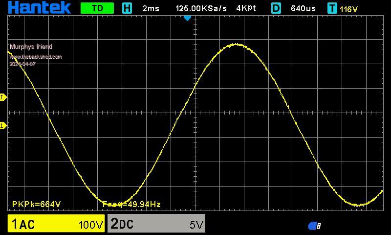
This is a screen shot of the sine wave a 1KW load:
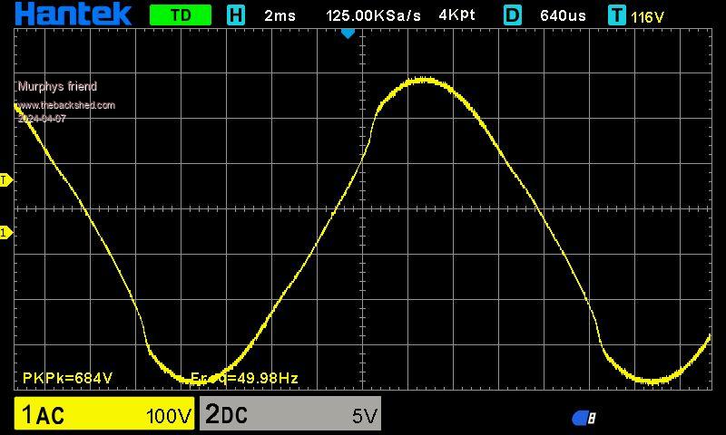
And this is how it looks at 5.3KW (all resistive load):
I also connected a 1KW microwave while the inverter powered about 3KW of heaters. Surprisingly, the sine wave looked no different to that with the 5.3KW resistive load.
I'm happy with these results and will now put the covers on and have that 6KW inverter power my house for a while. Let's see how that goes...
Murphy's friend Guru Joined: 04/10/2019 Location: AustraliaPosts: 678
Posted: 08:08am 07 Apr 2024
Copy link to clipboard
Print this post
Forgot to mention about the sat. info on the chokes. I do a saturation test for my home made chokes. The silicon steel core has a sharp knee in the DSO trace when the core saturates so it's easy to see.
The ring cores have a gradual increasing trace with no sharp knee on it. I select my saturation point when the trace slope gets to 45 degrees. These cores have a very good margin to cope with high current spikes IMO.


 .
.
 .
.
 . Got to keep busy doing something I enjoy doing in my retirement years.