
|
|
Forum Index : Electronics : Charge controller/logger with PIC12F675
| Author | Message | ||||
| vasi Guru Joined: 23/03/2007 Location: RomaniaPosts: 1697 |
Is based entirely on Glenn's controller/logger and software. The only difference is that we use one more pin so, you can use it as charger controller and logger same time. 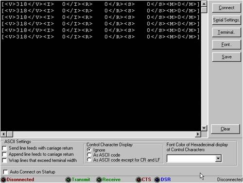
I wanted to use a PIC12F683, the one which PICAXE08M is based but I wasn't able to find it (is a to do). The PIC12F675 have half memory (1kb) than PIC12F683/PICAXE08M but I'm happy I managed to fit the program. I wanted to to data interpretation inside PIC but was not possible. I tested the program on a breadboard but only voltage measurement, not pulse counting because I don't have yet a pulse generator - I must make a development board with all peripherals I need... If some one have more posibilities than me at the moment, then please test the program (and report back here). Here is the archive which contain the program in Jal language and the hex file. 2009-05-04_161048_windcontroller.zip Archive updated! The compiler can be downloaded from here Schematic inside archive. Update 24 May 2009: ------------------- Here is the Oshonsoft Basic code for those don't like JAL: [code]' Dont forget to select 12f675 as target pic... Define CONF_WORD = 0x3184 Define CLOCK_FREQUENCY = 4 ' is 4MHz Dim volt As Word Dim amp As Word Dim rpm As Word Dim wspeed As Word Dim mode As Byte 'Calling OSC Factory calibration 'We must do this, is the only assembler area ASM: BSF STATUS,RP0 ASM: CALL 0x3ff ASM: MOVWF OSCCAL ASM: BCF STATUS,RP0 'registers settings OPTION_REG = %10000000 'no internal pull_ups 'setting pins as input/output 'GP1, GP2, GP3 and GP4 as input 'GP0 and GP5 as output '0 = output and '1 = input 'It looks like this: '- - GP5 GP4 GP3 GP2 GP1 GP0 '0 0 0 1 1 1 1 0 'TRISIO = %00011110 TRISIO.0 = 0 TRISIO.1 = 1 TRISIO.2 = 1 TRISIO.3 = 1 TRISIO.4 = 1 TRISIO.5 = 0 'defining which pin is analog and which digital 'again, '1 = analog '0 = digital ANSEL = %00011010 'ANS0 = 0 'ANS1 = 1 'ANS2 = 0 'ANS3 = 1 'prescaler for 4MHz 'ADCS0 = 1 'ADCS1 = 0 'ADCS2 = 0 GPIO = 0 CMCON = 7 'comparator off ADCON0 = %10000000 loop: 'cycle forever rpm = 0 wspeed = 0 Adcin 3, volt If volt > 571 Then GP5 = 1 mode = 1 Endif If volt < 558 Then GP5 = 0 mode = 0 Endif Adcin 1, amp Count GP2, 1000, wspeed Count GP3, 1000, rpm Serout GP0, 4800, "[<V>", #volt, "</V><I>", #amp, "</I><R>", #rpm, "</R><S>", #wspeed, "</S><M>", #mode, "</M>]" Goto loop End [/code] Tested only on simulator. It look much like PICAXE Basic... If requested, can upload also HEX file.. Hobbit name: Togo Toadfoot of Frogmorton Elvish name: Mablung Miriel Beyound Arduino Lang |
||||
| Gizmo Admin Group Joined: 05/06/2004 Location: AustraliaPosts: 5185 |
Hey Vasi Mate this is very good work. If you like I'll add it to the PicLog pages once you have finished the schematic. I've had a few requests for non-picaxe versions of the logger, and I dont have the time to learn C. Glenn The best time to plant a tree was twenty years ago, the second best time is right now. JAQ |
||||
| vasi Guru Joined: 23/03/2007 Location: RomaniaPosts: 1697 |
Hi Glenn, Sure you can post it, I will be glad. I will work hard but starting from tomorrow. Vasi Hobbit name: Togo Toadfoot of Frogmorton Elvish name: Mablung Miriel Beyound Arduino Lang |
||||
| Janne Senior Member Joined: 20/06/2008 Location: FinlandPosts: 121 |
It looks like you're using a change over relay to switch battery / dummy load on the turbine. Just a word of caution, a friends turbine in here had a similar configuration, and after about 6 months of usage it failed during a storm, leaving the turbine totally unloaded. I'd suggest you connect the relay instead to dump from the battery. edit. In this configuration the inductance of the generator will want to keep the arc burning between the relay contacts.. If you switch it to the battery side and the load is purely resistive it would be less prone to arcing. If at first you don't succeed, try again. My projects |
||||
| GWatPE Senior Member Joined: 01/09/2006 Location: AustraliaPosts: 2127 |
The changeover relay is a bad idea. Far better to use a second set of rectifiers and just switch the heater in and out, and leave the batttery permanently connected to the mill. If you use 3 heaters, you could use the raw AC and 3 relays. The AC is easier on the relay contacts anyway. If you dump from the batttery directly, avoid mosfets, as they normally fail as a short, and the battery will be discharged. Gordon. become more energy aware |
||||
| vasi Guru Joined: 23/03/2007 Location: RomaniaPosts: 1697 |
Ok then, Glenn's design will remain unchanged (my actual controller needs changing too). The logic needs a little modification. Thank you guys. Archive updated with schematic inside. Glenn, what do you think? As it is now, are pin differences. I can make to be hardware compatible as much as possible. Instead of "Serial In" pin of picaxe, let it be the relay and on "In 2" pin, Windspeed measurement. And all pin remain as you set them ( "Serial out" = Serial to PC, "In 1" = Current measurement, "Input 3" = Windmill RPM measurement, "In 4" = Voltage measurement, ). I'll wait for your response (when I started the work on this, my intention was to use it with a 2 wire LCD but when I saw that there is not enough memory, I changed my mind and I thought that is better to follow your design - I can use your schematic too). Hobbit name: Togo Toadfoot of Frogmorton Elvish name: Mablung Miriel Beyound Arduino Lang |
||||
| vasi Guru Joined: 23/03/2007 Location: RomaniaPosts: 1697 |
Is my turn to have problems on 12F675 controller. I get weird data on MCLR pin, set as digital input, of course. I used a pulse generator to test the RPM and Windspeed counting pulses. See RPM data (value between <R> and </R> tags): [code] [<V> 200</V><I> 686</I><R> 472</R><S> 10</S><M>0</M>] [<V> 204</V><I> 688</I><R> 468</R><S> 10</S><M>0</M>] [<V> 204</V><I> 688</I><R> 480</R><S> 11</S><M>0</M>] [<V> 204</V><I> 688</I><R> 466</R><S> 11</S><M>0</M>] [<V> 204</V><I> 688</I><R> 470</R><S> 11</S><M>0</M>] [<V> 204</V><I> 688</I><R> 450</R><S> 11</S><M>0</M>] [<V> 204</V><I> 688</I><R> 467</R><S> 11</S><M>0</M>] [<V> 204</V><I> 688</I><R> 470</R><S> 11</S><M>0</M>] [<V> 204</V><I> 688</I><R> 507</R><S> 11</S><M>0</M>] [/code] The value from <R> tags should be identical as in <S> tags. But are not and I don't know why (should work). Until now I used two 12F675 to be sure is not about a defective chip. And software seems to be ok. In last version, after analogue readings, I'm switching completely to digital, disabling analogue. No reason not to work. On other pins, counting pulses is working ok. Note: Ignore <V> and <I> values, are from experimental voltage dividers. Hobbit name: Togo Toadfoot of Frogmorton Elvish name: Mablung Miriel Beyound Arduino Lang |
||||
| vasi Guru Joined: 23/03/2007 Location: RomaniaPosts: 1697 |
Good news! No modifications needed because is working ok. The pulse counting wasn't accurate until I used (on breadboard) a optocoupler between TTL pulse generator and microcontroller pin to kill the noise. Glenn please, if you want, make a software version for this logger output. It output <A>,<I>,<R>,<S> and <M> The Gill's breadboard for circuit testing: 
Here are a 7805, a 4N35 optocoupler, 74LS00 as pulse generator, two voltage dividers, serial comm. cable and pic12f675 Oops! Javascript resizer didn't worked? P.S.: This controller is the result of this topic. Hobbit name: Togo Toadfoot of Frogmorton Elvish name: Mablung Miriel Beyound Arduino Lang |
||||
Bryan1 Guru Joined: 22/02/2006 Location: AustraliaPosts: 2136 |
G'day Vasi, After a good chat with Gordon he mentioned you had problems with taking the pic out everytime you need to program. Also he mentioned you had troubles with a bootloader on the pic's. It's good to see you got a 16f887 in another thread but to date I don't have any bootloaders for them. If you like I can pre-program a few 16f877a or 16f876a chips with a bootloader and send them over to you. Now I find 'Tiny bootloader' to be the best so I need to know which bootloader software your going to use first. The software I'm using now is Oshonsoft Basic which is similar to the picaxe and I really think JAL is suited to those who like it ( it aint me). Just mention if you want to go ahead with this and we'll have to organise Glenn with email details. Cheers Bryan  |
||||
| vasi Guru Joined: 23/03/2007 Location: RomaniaPosts: 1697 |
Hi Bryan, I can use the software which come with Tiny bootloader. I have a 16F877a but I'm interested also on 16F876a so if you can, send me a 16F876a pre-programmed. I know JAL is aware of Tiny bootloader. Also, I can program without problems on Oshonsoft Basic but I didn't found on it a solution to simulate count picaxe basic command but I know it can support assembler inside code... maybe I can do it... Thank you very much Bryan! Best regards, Vasi Edit: ------------------------------ Oops! Oshonsoft Basic really have a "count" function! Didn't saw it at first look. Hobbit name: Togo Toadfoot of Frogmorton Elvish name: Mablung Miriel Beyound Arduino Lang |
||||
| Bryan1 Guru Joined: 22/02/2006 Location: AustraliaPosts: 2136 |
Hi Vasi, Ok mate this week when I get some time I'll program some pic's with the tiny bootloader for you. Now just throw a spanner in the works  checkout this link and let me know if you want a 18f2550 pre-programmed with the code so you can make your own pickit2 clone. checkout this link and let me know if you want a 18f2550 pre-programmed with the code so you can make your own pickit2 clone.
We'll have to get Glenn organized so we can setup our own direct email link. Cheers Bryan |
||||
| vasi Guru Joined: 23/03/2007 Location: RomaniaPosts: 1697 |
You mean, this one? Hobbit name: Togo Toadfoot of Frogmorton Elvish name: Mablung Miriel Beyound Arduino Lang |
||||
| The Back Shed's forum code is written, and hosted, in Australia. | © JAQ Software 2026 |
