
|
|
Forum Index : Electronics : Inverter poor AC voltage regulation
| Page 1 of 2 |
|||||
| Author | Message | ||||
| Murphy's friend Guru Joined: 04/10/2019 Location: AustraliaPosts: 678 |
This is with my spare 6Kw inverter I am presently experimenting with. When I spotted wiseguys neat AC voltage regulation idea I had to try that  . That little 1:1 voltage transformer module would fit neatly directly onto my control board. . That little 1:1 voltage transformer module would fit neatly directly onto my control board.So I made two almost identical control boards, the difference being that one uses the EG8010 and the other Poida's Nano (with the 'no bessel' program). These boards can easily be swapped about in this inverter. Both boards give a very clean AC wave and the idle power is now only 19W for this 6KW toroid. However, having the AC voltage adjusted to 235V at idle, as soon as I load the inverter the AC voltage drops progressively, as much as down to 210V with a 4KW load (heaters). This voltage drop happens with the EG8010 *and* the Nano board. Here is the EG8010 schematic, voltage feedback is located in the top right corner. Any suggestions as to why that poor regulation are welcome.  |
||||
| wiseguy Guru Joined: 21/06/2018 Location: AustraliaPosts: 1297 |
Klaus try putting a 47p - 100p capacitor - with relatively short leads less than 10mm long between pins 5 & 6 of opamp A and retest. If problem is still present add another 47-100p between pins 2 & 3 of opamp A and retest. Hopefully one or both may do the trick. Did you use a ground-plane on the PCB ? Noise pick up on pin 6 & pin 3 of the A opamp is fairly sensitive to long traces or and no ground-plane. Good luck ! If at first you dont succeed, I suggest you avoid sky diving.... Cheers Mike |
||||
| poida Guru Joined: 02/02/2017 Location: AustraliaPosts: 1480 |
I would test the Vfb circuit to ensure that TP5 increases in DC voltage as the AC voltage increases going into the small feedback transformer. and Maybe watch Vfb (with the volt meter, with the meter's ground connected to the control board's ground) rise to about 2.5V as it outputs 235VAC, and then as you apply large AC loads, note Vfb. In the case of proper closed loop control, Vfb should remain stable and be 2.5V at idle AND when under load. (the 2.5V might be 2.7V or something else, no matter, it must remain stable) wronger than a phone book full of wrong phone numbers |
||||
| Murphy's friend Guru Joined: 04/10/2019 Location: AustraliaPosts: 678 |
Thank you, wiseguy & poida, for your suggestions, much appreciated. I did try wiseguy's capacitor suggestion today, no joy, if anything it made the regulation worse (down to 195V with the same load). I shall try measuring the Vfb as poida suggested tomorrow. Meanwhile here are some more details: The PCB has a ground plane on the component side. The AC voltage is sensed at the toroid winding connection, before any filtering. A picture of the control board:  And the other side: 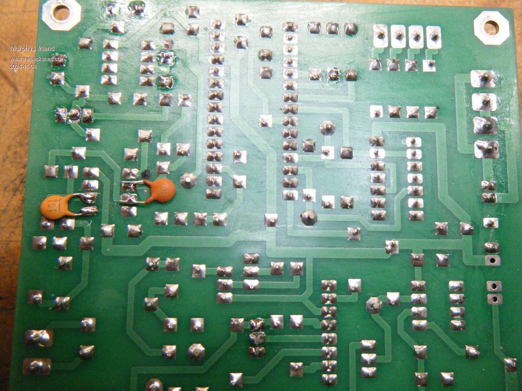 And here is how it is located: 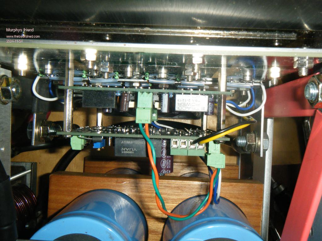 Looking down into the inverter, on top of the picture is the heatsink with the power board attached. The driver board is piggy backed onto this with short spacers and the control board on top of that on longer spacers. |
||||
| KeepIS Guru Joined: 13/10/2014 Location: AustraliaPosts: 2196 |
Hi Klaus, hope you get it sorted, nice PCB and construction by the way. I now sense AC after the filters, but it shouldn't make any real difference, although at initial setup and AC load testing I do measure the AC voltage at the same sample connection point to eliminate any cable or connection error as I was get caught out once, but I know I'm talking to an old hand at this sort of thing anyway.  NANO:Inverter V 8.2ks - Linux AvrDude GUI script V4.1 |
||||
| cuongngo66 Newbie Joined: 29/10/2024 Location: VietnamPosts: 2 |
hi poida, can you help me how to read peak - peak voltage like eg8010, i have read a lot of your posts and codes and followed on stm32, the sine wave generated from your code is very nice, i am having trouble in reading peak voltage for feedback |
||||
| poida Guru Joined: 02/02/2017 Location: AustraliaPosts: 1480 |
Hi cuong the Vfb voltage is only measured during the 2 zero crossing of the AC output. In the hardware designs used here, it is expected that there is some DC present that is proportional to the AC output voltage. Vfb will ALWAYS stay the same, as you increase the AC output or decrease it, since the code is a closed loop control, working always to produce the 2.75V DC on the Vfb pin on the Nano. Vfb can not be used to display the output AC voltage. For you to measure peak AC voltage, I suggest you use a separate circuit, on the AC output, bringing the 240 VAC down to something small, rectifying it and then displaying that quantity. You say you want peak voltages, so that means you use a peak follower type of op-amp design. Scale it down to 0 to 5V and convert via ADC, display values etc.. wronger than a phone book full of wrong phone numbers |
||||
| cuongngo66 Newbie Joined: 29/10/2024 Location: VietnamPosts: 2 |
Hi Poida, thank you for replying me, currently my circuit is coding unipolar spwm method, for 4 outputs, I have 4 tlp250 opto, the output sine wave 25khz is very good but I still can't handle the feedback part, can you help me with a circuit using op-amp to measure and then put it into the microcontroller? because i want to design my own circuit board like egs002 can be interchangeable 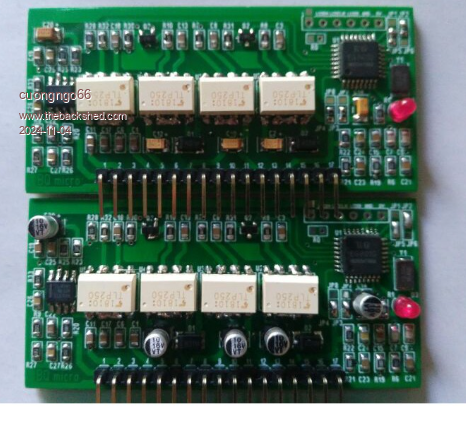 |
||||
| Murphy's friend Guru Joined: 04/10/2019 Location: AustraliaPosts: 678 |
I see that you are new to this forum. Please be advised that to add something to somebody else's topic which is not directly related to it is bad forum etiquette. It is simple to start your own thread, just click "new topic" on the home page. |
||||
| Murphy's friend Guru Joined: 04/10/2019 Location: AustraliaPosts: 678 |
OK, just did this measurement, the Vfb is rock steady at 2.76V at the TP5 post for AC loads from 0W to 2910W. Here is the AC voltage drop listed: idle: 235V 135W: 234V 500W: 231V 1780W:223V 2440W:209V 2910W:196V So, it's something else that's causing it, but what? I did reconnect the AC voltage sensing to a filtered AC output. Also. one choke connection which ran close past that little sensing transformer is now a fair distance away. The dual stack transformer core came originally from my scrapped warp inverter which was wound for a 225V secondary. To this I added 20 turns to keep the flux density well under 1 Tesla at 235V. The new primary to secondary ratio is 1:9 Any clues are much appreciated. |
||||
| KeepIS Guru Joined: 13/10/2014 Location: AustraliaPosts: 2196 |
Could be the winding ratio, if the Nano code you are running had the code for %PWM display, that could tell you if it was a possible transformer winding issue. You could try setting the AC output to 196V and then run the same load test, if the voltage stays close to 196v from idle to 2900W then it might also indicate a transformer ratio issue. _ Edited 2024-11-05 15:28 by KeepIS NANO:Inverter V 8.2ks - Linux AvrDude GUI script V4.1 |
||||
| Godoh Guru Joined: 26/09/2020 Location: AustraliaPosts: 675 |
Hi Murphy, Mike may be onto something there. I wind my transformers for 1 Tesla flux density. Mine are all 24 volt and so my transformer turns are worked out on 13 volts Primary and 240 volt secondary. I usually make the secondary 250 volts to allow plenty of headroom. I hope that your transformers are OK as changing turns is not much fun Pete |
||||
| tinyt Guru Joined: 12/11/2017 Location: United StatesPosts: 561 |
Hoping copper loss in the toroid transformer and inductor is negligible. Maybe there is something loose in the connections between the power mosfets and the toroid transformer/inductors. Voltage drop at the loose connection(s) increases as the AC load increases. It can be verified using a DMM as you increase the load. Edited 2024-11-06 05:54 by tinyt |
||||
| Murphy's friend Guru Joined: 04/10/2019 Location: AustraliaPosts: 678 |
Thank you all for the suggestions so far. I suspect I may have had a 'senior moment' when calculating the transformer turns ratio . The calculated flux density is 0.96 Tesla.Can somebody please confirm these measurements are correct for a 48V inverter: Powering the output winding with 235V AC I measure 26V AC at the input winding. Everything else was disconnected from the transformer for this test. The magnetising current was 136mA, this is about right for this 6KW toroidal core when compared to my other 6KW inverter. |
||||
| KeepIS Guru Joined: 13/10/2014 Location: AustraliaPosts: 2196 |
Hi Klaus, 28.4v <-> 240v at 16 watts for mine. NANO:Inverter V 8.2ks - Linux AvrDude GUI script V4.1 |
||||
| phil99 Guru Joined: 11/02/2018 Location: AustraliaPosts: 3317 |
= 9:1 = 18.46:1 So that appears to match ok. Perhaps the PWM is constant, not responding to feedback at all. Can you check with a scope? Un-plug the feedback op-amp and feed a voltage into TP5. Start at 3V and slowly decrease to 2.5V. AC output voltage should rise. Edited 2024-11-06 13:53 by phil99 |
||||
| KeepIS Guru Joined: 13/10/2014 Location: AustraliaPosts: 2196 |
That is where the Code with % of PWM code display is so handy. I have seen this exact thing happen in testing when the turns ratio is not right, very poor AC regulation and Duty cycle of 96% at idle. NANO:Inverter V 8.2ks - Linux AvrDude GUI script V4.1 |
||||
| Murphy's friend Guru Joined: 04/10/2019 Location: AustraliaPosts: 678 |
Thanks but there is no display with the original Nano code my inverters run on. Even if there was a display, my geriatric brain might find it difficult to fully grasp the meaning of % of PWM or idle duty cycle  . . Strangely, this is not the first inverter I built, I have 4 others here (of varying sizes) which do not have that problem. So, you might understand why I am perplexed by this outcome. I shall try phil99's suggestion tomorrow. Meanwhile, today I experimented with another choke and got a slightly better ACV regulation with that, will have to find the best combination for that. |
||||
| Godoh Guru Joined: 26/09/2020 Location: AustraliaPosts: 675 |
Hi Mr Murphy, I too was wondering if your choke is part of the problem. I had a look at my inverter today, and it was sitting on 237 volts. I turned on the washing machine it stayed on 237, then started a 1500 watt motor and it stayed the same. My chokes are really just hit and miss jobs. From memory my choke in this inverter is just a couple of torroids with about 4 or 5 turns on each. One torroid on each leg. Good luck with the adjustments, I hope changing the choke sorts it out. Pete |
||||
| wiseguy Guru Joined: 21/06/2018 Location: AustraliaPosts: 1297 |
The only problem I perceive is as I described initially, noise pick upon your first "A" opamp. To my mind this also reinforces that we are in the right area for the right reasons but with the wrong cure tried first, causing the issue to be worse. I thought adding the capacitors might help, instead of having to add a faraday screen. That is a piece of Aluminium plate between the Power drive board and the controller PCB/s. Dex had exactly the same issue with his inverter and it was solved 100% with the screen. The capacitor was an untested guess which should have helped for filtering fast witching spikes (in theory...). 4 more 10mm hex spacers and a metal plate is all thats needed. I have looked at your schematic and I think there may be an issue with the link on the corner of the PCB with the ferrite bead, which appears to be the battery negative power supply return wire for the PCB. I normally connect the battery feed wire via a single connector pin direct to the ground plane. If you put a sheet metal screen plate under the PCB the Ferrite bead needs to go! The ground plane of the PCB must be solidly coupled to the metal screen plate, the bead places HF impedance between the two. If it has to remain as the battery connection just use a wire link without a bead. I would choose to place a 10nF MLCC capacitor instead of the link, and supply controller power via the -55V node shown on the schematic or other similar connection to the ground-plane. The schematic shows what appears to be a +/- 55V source to something else which is for what ? Best practice is to power external stuff directly not via the PCB. I always have only the one DC coupled negative connection to the battery minus for the controller and that would be at the point that the Battery negative connects to the chassis or to the Power PCB negative point. Its only function is for the miniscule power the controller needs and as a return sense wire for the battery voltage measurement. Another good thing to do with floating Cmos nodes in a dual opamp in a noisy environment is to tie them somewhere. I would tie pins 6 & 7 together on the unused "B" opamp and ground pin 5 so its function is as a voltage follower which is now referenced to ground. The reason why your other inverters did not have this problem as I perceive it is because they did not use an active amplifier/rectifier in the feedback path, which does have some nodes that would be sensitive to noise. Some copper foil a bit bigger than a larger postage stamp and soldered to a couple of ground points covering the sensitive nodes & traces might sort the problem out without making a full metalwork shield. - I never envisaged that a controller board would be placed/bolted in such close proximity to the power section in a build. The fact the feedback voltage is rock steady I submit means the feedback voltage & servo loop is operating perfectly. If the output volts are falling but the feedback is fine and rock steady at 2.76V that is because noise is being picked up by the Opamp "A" on your PCB and added to the feedback signal. As it is now artificially at 2.76 due to feedback + noise injection then the PWM reduced the output voltage so output voltage + noise was equal to 2.76V. Simple huh ? Servo loops do play with your head a bit and cause you to question your sanity especially when trying to interpret what is cause and what is effect I can't be of much further help as I have no idea of your physical implementation of the PCB track lengths etc. But a shield plate grounded to the PCB ground-plane under the controller should solve the issue. Mounting the controller a bit more distantly from the "noise" would assist, the opto drive signal cables can easily withstand longish runs. With regard to AC voltage stability/accuracy the best place to connect the voltage sense transformer IMO is downstream from the toroid - as close as possible to the final AC output, that way most voltage drops through filters etc are compensated for. But definitely before any switches/relays etc that would remove the ACV sense wires from the Toroid AC output or that would lead to max uncontrolled AC voltage at 100% modulation - a really bad plan. Edited 2024-11-08 10:02 by wiseguy If at first you dont succeed, I suggest you avoid sky diving.... Cheers Mike |
||||
| Page 1 of 2 |
|||||
| The Back Shed's forum code is written, and hosted, in Australia. | © JAQ Software 2026 |
