Notice. New forum software under development. It's going to miss a few functions and look a bit ugly for a while, but I'm working on it full time now as the old forum was too unstable. Couple days, all good. If you notice any issues, please contact me.
Murphy's friend Guru Joined: 04/10/2019 Location: AustraliaPosts: 678
Posted: 08:36am 09 Dec 2024
Copy link to clipboard
Print this post
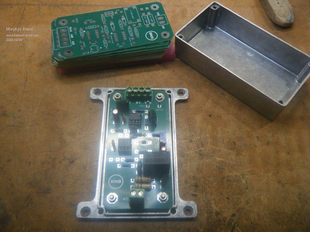
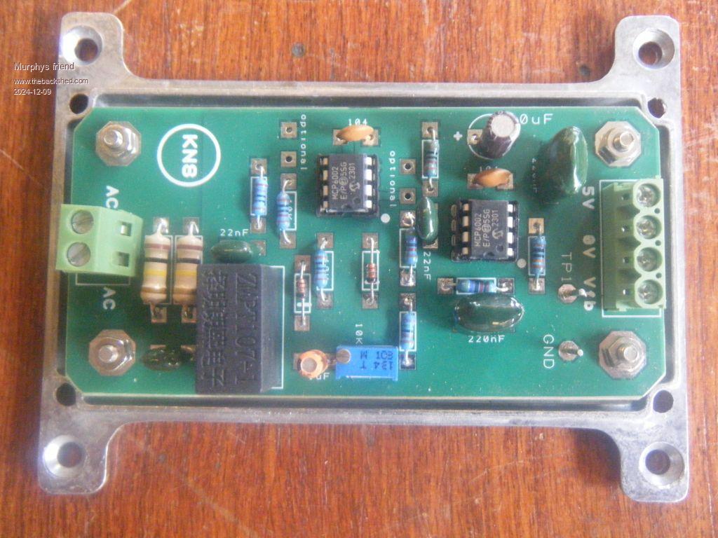
For those who would like to try wiseguy's clever Vfb method on their existing Ozinverter.
This board replaces the little 12v transformer and associated components used for Vfb in Ozinverters.
I found it to work much better, especially if the inverter is used with a GTI in a minigrid application. The original Vfb method could rise the AC by 10V or more with a decent GTI feedback and little load. Wiseguy's Vfb method kept that rise to 2V or so in similar conditions.
The board will fit into a little dicast box for complete shielding. This box is at DC ground potential so it must be mounted insulated from the inverter housing which usually is at AC ground potential.
I have 6 spare boards, free (including postage in Australia) to give away. Please let me know if you want one.
Here are a few pictures:
Revlac Guru Joined: 31/12/2016 Location: AustraliaPosts: 1282
Posted: 10:53pm 09 Dec 2024
Copy link to clipboard
Print this post
Nice, the box is a good idea, easy to fit in. Cheers Aaron Off The Grid
Godoh Guru Joined: 26/09/2020 Location: AustraliaPosts: 675
Posted: 07:17am 12 Dec 2024
Copy link to clipboard
Print this post
I don't know how the Oz inverter boards control voltage feedback but your boards look great, if they keep the voltage rise that low. I use 8010 based boards in my inverters, they have a small transformer too that is hooked up for voltage feedback, so maybe it is a similar arrangement. I have never thought to check my voltage rise when the GTI inverters are backfeeding. I will get the meter out in the next days and have a look. As I don't have circuit diagrams for the Aliexpress boards I would not know where to hook a circuit like yours in. I just had a look at the diagram for the EGS002 boards I have, they seem to use a resistor and capacitor arrangement to supply feedback, but my diagram does not show a transformer. I know that there is one on the board, but the Chinese are not big on details when it comes to what their boards do. Pete
Murphy's friend Guru Joined: 04/10/2019 Location: AustraliaPosts: 678
Posted: 04:22am 13 Dec 2024
Copy link to clipboard
Print this post
Pete, the EG8010 chips in the Ozinvereter (and possibly the EGS002 boards) use pin 13 for the Vfb input. As per EG8010 specs (worthwhile to download) this pin expects 3V DC which is the rectified output of that little transformer.
I too used EGS002 boards in my early inverter tinkering, have moved on from them long ago as they were prone to cause blow ups, especially if their Ifb circuit was not disabled.
If you were on the grid you'd notice the AC going up around lunchtime when everybody was dumping solar power into a grid that did not really need that much power input.
Your mini grid is no different which it is so important to shut down the GTI input once the batteries are fully charged and no other big load has use for the extra GTI power.
Godoh Guru Joined: 26/09/2020 Location: AustraliaPosts: 675
Posted: 08:57pm 13 Dec 2024
Copy link to clipboard
Print this post
I have voltage controlled relays on my GTI inverters. The relay switches the output of the GTI off to make them anti island. They are working great that way. I have seen ( on clear sunny days) up to 6kw of power going into our car when charging, which is a big jump from the 2.4 Kw that was all I could get into it before the GTI's were added. What you say about the current feedback is interesting. Is it worth disabling the current feedback? Pete
Murphy's friend Guru Joined: 04/10/2019 Location: AustraliaPosts: 678
Posted: 02:51pm 14 Dec 2024
Copy link to clipboard
Print this post
Well, if, as you said, you turn off your GTI, thus disconnecting it from your mini grid, when your batteries are full, then you won't have any current feeding back into your batteries.
Think about how it works. Your battery powers your inverter. Your GTI forms a mini grid with your inverter when connected.
Your inverter *and* the GTI provide power to your load, the inverter from the battery and the GTI directly from the sun.
If the load reduces, any power from the GTI back charges your battery. You monitor the battery voltage and disconnect the GTI when the battery is full - This is called a "bang bang" voltage regulation .
Your battery still gets charged after that from your solar MPPT regulator. This is how my system works actually. With my system, the charge from the MPPT is sufficient to supply the load during sunshine, after the additional morning charge from the GTI has finished. With little sunshine the GTI stays connected for most of the day.
There is a way to soft regulate the GTI back charging and I know of one forum member who does that. In my case the additional complexity is not required, the GTI is used as a boost charger on most mornings only. A battery voltage controlled relay disconnects it when the battery is charged to its absorption voltage. Over night, the battery voltage drops to the preset relay re connect level and the cycle repeats in the morning as the sun appears.
Godoh Guru Joined: 26/09/2020 Location: AustraliaPosts: 675
Posted: 10:51pm 14 Dec 2024
Copy link to clipboard
Print this post
I was more thinking of disconnecting the current limiting circuit for when the battery inverter is supplying loads. It does not like my mig welder too much. It is fine when welding thin metal, but if I turn the current up then it goes out on overload and then waits a while to reset. I have tried adjusting the current limit but it doesn't want to play with the welder on high current settings. The welder is a 180amp mig, it only has a 10 amp plug but I am guessing it pulls more than 2,4 kilowatts when welding. I will have a look at the specs sometime. Thanks for your help pete
Murphy's friend Guru Joined: 04/10/2019 Location: AustraliaPosts: 678
Posted: 08:47am 15 Dec 2024
Copy link to clipboard
Print this post
Now I see what you are getting at.
My inverter did not like my old abrasive chop saw, it tripped the AC current sense every time I tried to use it.
So, I connected my peak current sensor - KeepIS described it in a tread - and this shot up to 400A peak DC from my nominal 53V battery bank on startup. This would correspond to about 4.5 times less peak amps at the inverter's AC output.
The problem is my inverter's AC current sensing works on instantaneous values. It would have to be set way too high to cope with those loads. Then I remembered that there was a 25A AC circuit breaker in my (6KW) inverter. These can cope with high instantaneous loads but trip reliably from an overload.
Now I have disconnected the inverters AC current sense, the AC C/B is good enough to protect it from overloads. But my inverter is a home made job, not a Chinese (usually way over rated) product .
You could try something similar. If your mig welder has a 10A plug and your inverter is rated for 2.4KW continuous *and* you have a suitable AC C/B, then it should work.
Keep in mind that there is most likely some mention in the welder's instructions that the 180 Amp are not continuous. You have to give the thing a pause now and then to let it cool down.
Godoh Guru Joined: 26/09/2020 Location: AustraliaPosts: 675
Posted: 02:26am 16 Dec 2024
Copy link to clipboard
Print this post
Thanks for that Mr Murphy, yes the welder does have short time ratings, I will never weld stuff thick enough to need the 180 amps it can output. It looks pretty easy to just disconnect pin 1 on the 8010 board to disable the current sensing. I do have a type A RCD circuit breaker on the AC side so as you say that should be fine for real overloads. Cheers Pete
FET cemetery Regular Member Joined: 17/04/2024 Location: AustraliaPosts: 74
Posted: 07:11am 16 Dec 2024
Copy link to clipboard
Print this post
"It looks pretty easy to just disconnect pin 1 on the 8010 board to disable the current sensing." I always tie pin 1 to ground with a 1k (if I remember correctly) resistor on my EGS002 boards.No stone unturned, no FET unburned.
Godoh Guru Joined: 26/09/2020 Location: AustraliaPosts: 675
Posted: 07:41am 16 Dec 2024
Copy link to clipboard
Print this post
Thanks Mr Fet, sounds like a plan. Your nom de plume sounds ominous. Fortunately since switching from using Powerjack inverters I have not had any dead fets. I used to repair high frequency inverters for friends, popped fets were always a problem thanks Pete


 .
.