
|
|
Forum Index : Electronics : Another three-stack toroidal transformer
| Page 1 of 8 |
|||||
| Author | Message | ||||
| FET cemetery Regular Member Joined: 17/04/2024 Location: AustraliaPosts: 74 |
Inspired by KeepIS of course. Well the stars aligned on marketplace a couple of months ago, and after 5 hours driving (down to Melbourne and a zigzag across the metropolis) and surprisingly, change from $200 for the lot, I had these three beauties in the shed. 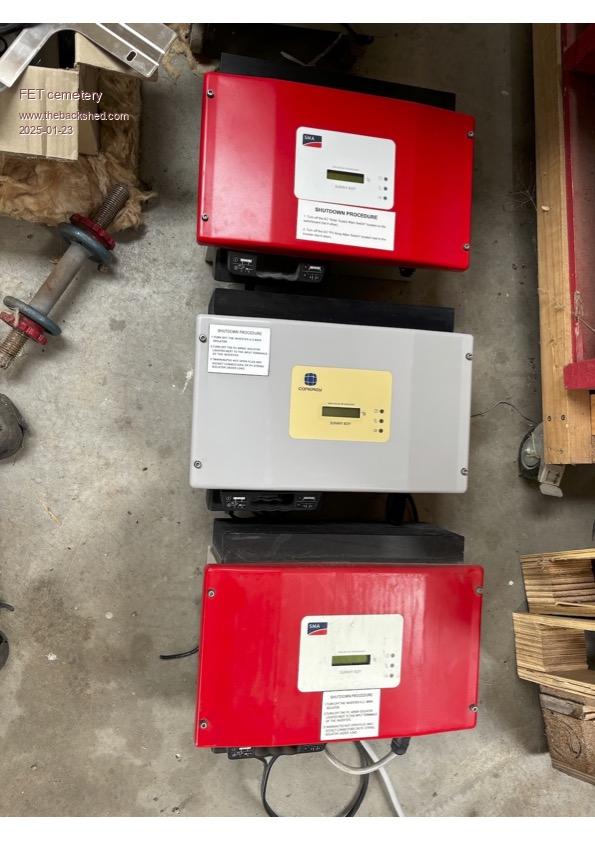 No stone unturned, no FET unburned. |
||||
| FET cemetery Regular Member Joined: 17/04/2024 Location: AustraliaPosts: 74 |
SB1700's. Lots of goodies inside, not least the heatsinks which will be perfect once I get around to building the Wiseguy boards. 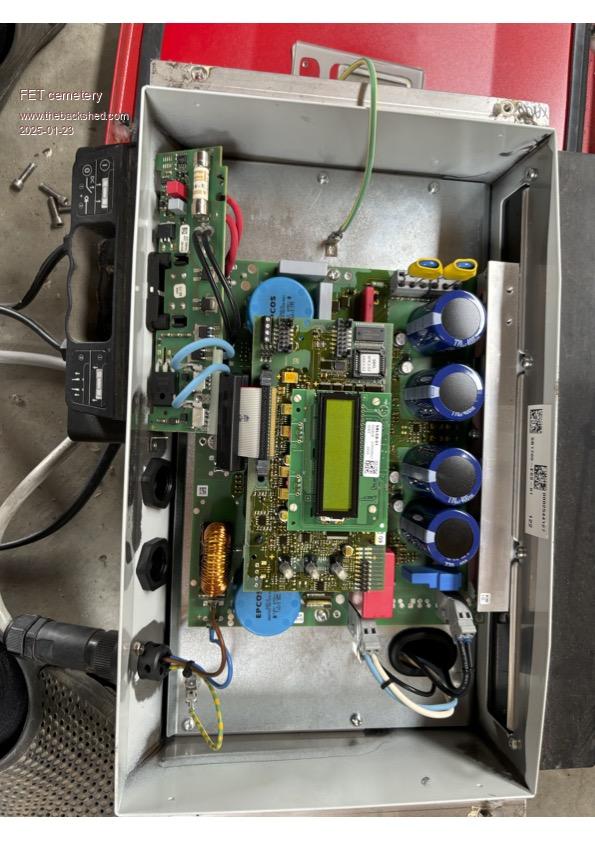 No stone unturned, no FET unburned. |
||||
| FET cemetery Regular Member Joined: 17/04/2024 Location: AustraliaPosts: 74 |
Got to the transformers and oops.... They're all completely potted in some sort of epoxy with a plastic case. I may have said some bad words. The transformers have 93V secondaries like KeepIS had, but I don't think they're exactly the same. 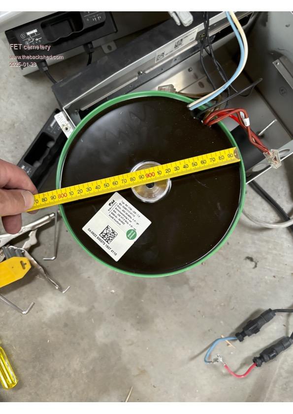 These are some of the weapons I used to liberate the inner toroids. It's not power electronics without power toools after all is it! 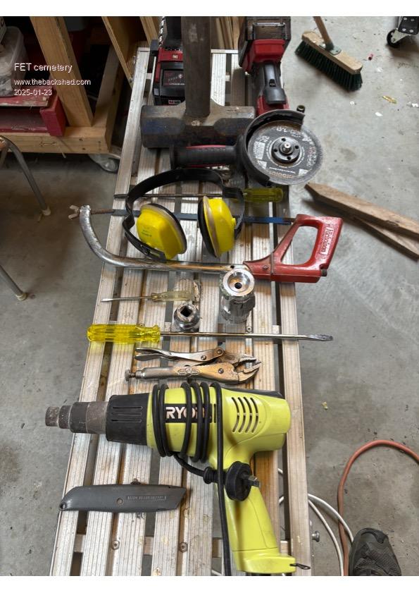 No stone unturned, no FET unburned. |
||||
| FET cemetery Regular Member Joined: 17/04/2024 Location: AustraliaPosts: 74 |
The method used was to cut the green plastic with a butane soldering iron and heat it gently with a heat gun until it just peeled off, in a well ventilated area of course. Next, I drilled multiple holes next to the aluminium spindle with an old 8mm drill bit, wiggling it around until the spindle was loose enough to tap out with a hammer. Then it was a simple matter of brute force unwinding the 240V outer winding, dragging it through the epoxy and occasionally using a chisel or some heat when the going got tough. This was hard work, took a couple of hours per transformer and I could only manage an hour or so a day. There was a few kilos of unsalvageable copper 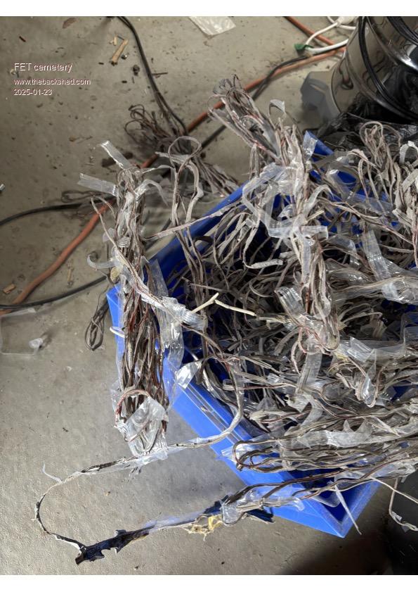 And finally the prize. 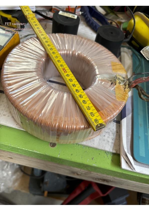 The 93V winding is actually two separate windings in parallel. No stone unturned, no FET unburned. |
||||
| FET cemetery Regular Member Joined: 17/04/2024 Location: AustraliaPosts: 74 |
Well I eventually got the three out, wired them together, wound a 7 turn test coil and fed 240V into the assembly - through an old 60W incandescent globe at first just in case. 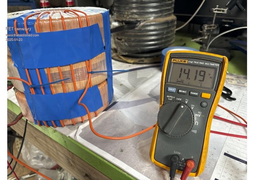 You can see the reel of 64mm cable in the background which is what the primary is now wound with. Fed it through an ac power meter, showed it drawing 19W unloaded which I guess is the baseline magnetising power. Impressive for 30+ kilos of core. To be continued, I'm a bit time poor at the moment. No stone unturned, no FET unburned. |
||||
| FET cemetery Regular Member Joined: 17/04/2024 Location: AustraliaPosts: 74 |
Well this is where it got a bit confusing for me. So the idea is, after the dismantling you're left with 3 toroids each with a 93V winding. Stack them, join the windings in series and wind a new primary around the whole assembly appropriate for the voltage of the inverter you're building. 93 x 3 = 279, de-rate it a bit and you've got a ready made 240V secondary. The no-dig garden bed of transformers. Feeding 240V in to this assembly I expected each winding to have 80V across it but no, one had 91V, one was 85V and the one in the middle was at 64V. Wondering if this was the flux in the outer two affecting the middle one I changed their positions in the stack. With the one in the middle now on top it still showed 64V. What was going on? Out with the trusty digitech induction meter. Two of the toroids showed 59 and 53mH, close enough, but the one with the low voltage was only 28mH. Pretty much half. As far as I can tell these are identical machine-wound transformers. Multiple sanity checks of my wiring confirmed that I hadn't done anything stupid. All I can think of is that the cores are from different batches of metal. I'm open to suggestions here, this has me puzzled. Jumping ahead a bit here, with a primary wound and the transformer working in an inverter, the same discrepancy is there at no load. As I had suspected (hoped?), increasing the load on the inverter reduces the voltage difference. At 4kW output there's only a couple of volts in it. Running at that output for several hours the thing gets warm, but evenly. No hot spots that can't be accounted for by airflow / convection, all three toroids at about the same temperature. A good outcome, but still a bit puzzling. No stone unturned, no FET unburned. |
||||
| wiseguy Guru Joined: 21/06/2018 Location: AustraliaPosts: 1291 |
The uneven distribution of voltages was a bit of an unexpected surprise to me as well. I guess that the 64 volt measurement meant that its core losses whilst not too bad was higher than the other two so the result was what you found. As soon as a load was applied though all 3 appear to have contributed quite evenly to the total power and the small magnetising power differences paled into oblivion. I note you referred to having a primary wound and putting 4KW through it from an inverter, does that mean you have the have new inverter running now? That stack of 3 toroids must ne a handful to shift around ! I have a few bags of toroid winding detritus also, bloody hard on the hands unwinding it all - I used the same method to remove the centre of the toroid too. It all put me off pulling any others apart until the memory fades a bit more. If at first you dont succeed, I suggest you avoid sky diving.... Cheers Mike |
||||
| FET cemetery Regular Member Joined: 17/04/2024 Location: AustraliaPosts: 74 |
I really need to write stuff down and not rely on memory. At 4.3kW the voltages on the coils are 84.7V 71.9V 83.2V top to bottom. (Maybe I wanted to forget this). This is after several hours charging the car at this output. Thermally everything still seems pretty even across the stack. The voltages are much closer than when unloaded but still significantly different. I'm inclined to think this doesn't matter as long as none of the cores is nearing saturation. If only I hadn't thought to measure it I'd still be in blissful ignorance! No, I haven't got the new inverter together yet Mike, it's next on the list. Is there a final version of the software, I've done a site search but can't seem to find it? Software is definitely not one of my strengths, and programming the nanos will have me procrastinating if I don't get straight on to it. Moving the toroid assembly does require some planning... No stone unturned, no FET unburned. |
||||
Revlac Guru Joined: 31/12/2016 Location: AustraliaPosts: 1265 |
Interesting, I don't have any of these type of toroid configurations to check values against, just looking at the info provided, the voltages are a little different when wired in series a proper test would have been to test each individual toroid before assemble and it would give us a better idea whats going on. certainly different core material would account for a bit different induction value but not the full story, the different voltage is more likely down to different turns on each core, even though they should be machine wound they might not have followed the same plan (number of turns) in different winding machines, and would also account for some different inductance Individual core testing would give us a better idea, before taking the 240vac winding off they may have had different idle current on each core I have spent half the day in the hot sun so I may be talking nonsense  , but I'm sure there is at least one clue in there. , but I'm sure there is at least one clue in there.Looks like it will work fine for your inverter as you have it, good to know, look forward to seeming you build.  I wrote this out BEFORE your Reply, so just ignore it if you like Cheers Aaron Off The Grid |
||||
| wiseguy Guru Joined: 21/06/2018 Location: AustraliaPosts: 1291 |
Revlac does have a point, the turns ratio for Toroids for identical units sometimes have different turns ratios. 2 identical 3kW toroids I have are 195 and 212 turns on the mains winding. I think for 93V then that would be ~ 85V (or ~ 100v)for the 8% difference, assuming core material was the same, but obviously the flux would have that 8% difference too. Poida has given me a working version of the software to test, which I have not been able to fault. We have discussed various methods of making the software available to bona fide builders. However for the same reasons that I have not made the PCBs available as open sourced such as on JLCPCB where you can share your PCB and project designs. The reasons are that between us there have been hundreds of hours of development & testing time for the hardware and software. If we made everything freely available there is nothing to stop some entrepreneurial chap from commercialising our hard work and making money from it. That is not in the spirit of our efforts which was intended to help individuals make a working inverter with minimal risk. We did not make a cent from our efforts (quite the opposite) that is why we are a little protective of the IP involved. I have shared PCBs freely at cost, available for prices from ~25c to ~ <20.00 including schematics, parts lists, assembly and testing information etc. Yes it could still be copied/recreated but I have some satisfaction in knowing there will be a fair amount of pain and effort & cost involved as its not just given to them for free on a platter. Poida is having a bit of a back seat break as I am, had to catch up on a number of other domestic bits and pieces. Our last discussion was that the inverter project builders can email Poida or Myself for the Nano programming files and at least we have some control of who we are supplying the software to. Poida was going to create an idiots guide (for me I think...) on the steps involved to install the Arduino software environment and ports, drivers etc that may need to be installed and the cable and connection to the target Nano module and finally uploading the software to the target Nano. Poida and I have not communicated for many weeks now so not sure of the progress, but don't worry when you need code it will be available. KeepIS has also created code for the Nano that has other features and operation to suit his requirements and he makes it also freely available. My only stipulation is that if you have just built your inverter and want help with any issues debugging etc please be using the Poida code as I am very familiar with that. When it is working fine by all means consider using the KeepIS code as I believe it is quite robust - but I choose to just stick to the Poida code for now having spent so long with it and being a bit software challenged, I don't want to learn a second lot of firmware for now. Edited 2025-01-24 18:29 by wiseguy If at first you dont succeed, I suggest you avoid sky diving.... Cheers Mike |
||||
| KeepIS Guru Joined: 13/10/2014 Location: AustraliaPosts: 2151 |
First off, great to see you went the extra mile removing the potting on those different units   The Toroids not potted are the early 1200 watt units. The unloaded voltage difference on mine was around 4 volts on one Toroid, the other two were 93v, on both sets of three-stacked Toroids. I agree, running for several hours with no obvious hot spots is a good outcome, a small amount of convention cooling or assisted cooling via a silent low speed fan blowing through the cores will allow them to run cool. FYI: Mag current, AC in AC out unloaded. 26.8v = 225v @ 13.6 watts 27.3v = 230v @ 14.5 watts 28.4v = 240v @ 16.0 watts 29.8v = 250v @ 18.0 watts 31.0v = 260v @ 19.0 watts 32.0v = 270v @ 22.7 watts 33.3v = 280v @ 26.0 watts As you know I have 6 Toroids in my Inverter running 24 - 7 without a single glitch, startup loads drawing over 520A Peak DC input are easy, this inverter can supply twice that surge input current, but in the interest of not taxing the FETS I have limited DC input current to a bit under 1000A. FYI: Hex file for Nano . Edited 2025-01-25 15:14 by KeepIS NANO:Inverter V 8.2ks - Linux AvrDude GUI script V4.1 |
||||
| KeepIS Guru Joined: 13/10/2014 Location: AustraliaPosts: 2151 |
I just noticed the above info. Do you know the diameter of the wire used? Just out of interest, were you able to confirm that each toroid had a 93v volt winding, mine had an ID sticker on the toroids. I wonder if one of the inverter models was slightly different, I know some of the higher power units were wound to a different voltage. NANO:Inverter V 8.2ks - Linux AvrDude GUI script V4.1 |
||||
| analog8484 Senior Member Joined: 11/11/2021 Location: United StatesPosts: 201 |
It's a possibility that is rather unlikely. The great work you and others have done are highly commendable but unfortunately the commercial opportunity for LF inverters with big transformers has diminished greatly. The top 2 leading vendors of LF inverters in the US have both recently stopped making them after decades. The broad market has spoken and HF inverters has won despite some real advantages of LF inverters. It's the same reason why the Warpverter also has limited commercial opportunity. Not sure what you want to get out of your work, but there are established mechanisms (e.g. GPL) for open source hardware/software projects to ensure proper attribution/credit that you may want to consider. Edited 2025-01-26 04:01 by analog8484 |
||||
| KeepIS Guru Joined: 13/10/2014 Location: AustraliaPosts: 2151 |
I understand Wiseguys concern with respect to helping builders fault find his Inverter design and PCBs using only the release code. Anyone can copy his design, which you are free to do and some have with great success, but they are smart enough to understand that if it blows, they can't immediately blame the designer, and can't expect the designer to spend a lot of his/her time fault finding the problem for them. This is a very powerful inverter, any mistake made by someone modifying the Nano Code will likely spell disaster. There is also the problem with modifying code without a thorougher understanding of the electronic design, the timing and code limitations of the Platform (the Nano in this case) and the electronic Interface timing and the effects of running in a relatively harsh environment with respect to RF noise. A seemingly simple change in code my cause instant disaster, or a future disaster that may not be apparent under normal running conditions. I said right from the start that I would help anyone who uses my code. I don't think many builders have thoroughly abused and tortured Wiseguys hardware design to the extent that I have, and over a long period of time. I have great confidence in Wiseguys Inverter design, the core SPWM code by Poida is brilliant and robust and proven. I've seen designs being trashed on other forums because of a mistake made by the builder, and some won't admit it was their build error. I can see why the code should be carefully distributed at this early stage, this is why my version is in a Hex file format at the moment, I believe a few builders are using it and I know it does not glitch of fail near the upper limits of the Inverter hardware design. If enough Inverters are built and proven to run correctly, there is little chance of someone trashing the design when running official software. . Edited 2025-01-26 09:40 by KeepIS NANO:Inverter V 8.2ks - Linux AvrDude GUI script V4.1 |
||||
| wiseguy Guru Joined: 21/06/2018 Location: AustraliaPosts: 1291 |
My comments of someone else making money from our hard work, has more to do with countries like Nigeria, India (and a lot of other countries too) etc where the typical person cannot afford a 12KW HF inverter but they can afford to build stuff essentially from items that others are discarding. Or they can afford to buy ready built modules and use "free" software to make it all work. I used the term "some entrepreneurial chap" it was not meant to represent the likes of Siemens or Xantrex etc just someone exploiting a situation for their own ends. I'm probably not sure either and never looked that far ahead. I get satisfaction out of success - that does not have to be financial it may be just taking on a challenge and succeeding. I also like sharing my success I think I said before that if I create something that works it has to be able to be reproduced to be of benefit to others. I wanted like minded inverter builders to be able to create their own low cost powerful and reliable inverters from a working recipe. Last comment; I also am undecided how to proceed from here I have found the last few mostly multi international orders took a lot of effort time stress etc to order package and send out, so I don't think I want to do it that way again thus I am contemplating where to from here. I never wanted another "job" and think I would really like to move onto some other things I enjoy with much less stress & effort. If at first you dont succeed, I suggest you avoid sky diving.... Cheers Mike |
||||
| FET cemetery Regular Member Joined: 17/04/2024 Location: AustraliaPosts: 74 |
I'm kicking myself a bit for not looking in to this a bit more before the transformer was assembled. Pushing the primary wires aside I can get to about 5cm of the inner winding, counting turns gives 23 on each core over this length, identical. Stacked on top of each other before assembly they looked identical to the extent that I didn't even consider that they may be wound differently. Would one batch of core material being way better than needed and another just good enough account for what I'm seeing? Wiseguy - fully understand your position re IP. I'm amazed at and grateful for the time and expertise that has been volunteered for this project, thank you all! Don't know much about open source but if your work was blatantly stolen wouldn't you still have to lawyer up to do anything about it? Hardly a fitting reward for your effort. KeepIS - Thanks for the link. One of he units was Conergy branded but all had identical labels / specs on the side of the case.The only difference I noted was that the big caps were different brands and slightly different values in one of the red sunnyboy units. All the transformers had identical labels, primary 93V 50/60Hz secondary 230V 7A. Wire diameter is about 2.1mm, 2.15mm with the enamel on, giving a bit more than 6mm sq total cross section of the 2 windings if my maths is right. My gut feeling is that this monster is capable of 7 or 8kW continuous with forced ventilation. It will do 4.3kW all day at 35 degrees C ambient temperature with a fan running half speed drawing air up the middle. No stone unturned, no FET unburned. |
||||
| Revlac Guru Joined: 31/12/2016 Location: AustraliaPosts: 1265 |
 Thats Exactly the way I see it, and in doing this you have also learnt and built your own and others help test it, its not just inverters but many other contributions. I do the same with the work (fixing other peoples stuff) at home, but thats another topic. I hope people here can help FET cemetery build perfection without smoke. Edit: okay I'm late to the party again.....I just got the bread maker going. Edited 2025-01-26 12:22 by Revlac Cheers Aaron Off The Grid |
||||
| KeepIS Guru Joined: 13/10/2014 Location: AustraliaPosts: 2151 |
Those are slightly higher power Toriod windings compared to mine, I have thicker single layer windings of 118 turns on each Toroid, when stacked and wired in series, I have 14 turns of 2AWG cable rated at 188A continuous through each 3 stack toroid, there are two of these 3 stack toroids in the inverter. I can confirm that when running at just under 9kW (4.5kW each toroid stack) the toriods hold around 38°C with silent slightly enhanced convection airflow, the Fans switch to full airflow when either toriod reaches 40°C, they have only come on a few times but don't run for long, they quickly cool to 36°C, the 2 Toroids and 4 chokes have never felt more than "slightly" warm to touch. BTW the fans on full are almost inaudible. Everything else is always around room temperature. It's a beast . NANO:Inverter V 8.2ks - Linux AvrDude GUI script V4.1 |
||||
| analog8484 Senior Member Joined: 11/11/2021 Location: United StatesPosts: 201 |
That aligns very well with the motivation of many people who participate in open source projects. Few open source projects become meaningful commercial success but many do get satisfaction and recognition from user adoption. I think OzInverter is a good example of an open source inverter that got good recognition but not much commercial success. The various OpenInverter.org EV inverter projects may have more commercial success but satisfaction and recognition are still the main reward for the creators. I certainly think you deserve to have your inverter project recognized. WiseVerter? Or WiPoVerter? to also recognize poida's contribution. That's too bad. I think that's one reason why many open source HW creators decide commercialization is not worthwhile (at least not at small scales). |
||||
| FET cemetery Regular Member Joined: 17/04/2024 Location: AustraliaPosts: 74 |
On with the show, time flies! I found some adhesive backed neoprene from a long-forgotten project, cut it into rectangles and used it to keep a bit of a gap between the windings on the adjacent cores. 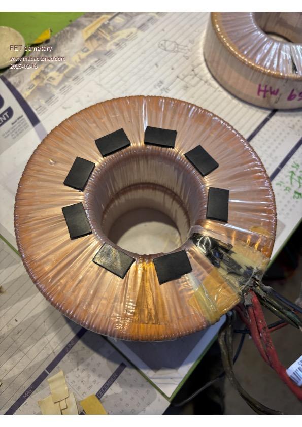 The only thing I actually purchased new was some high temperature thermosetting fibreglass electrical tape to hold the assembly together. The primary is 12 turns of 00gauge 64mm cable rated at 370A. Bought a 30m roll of it at a clearing sale for $80, 15 years ago. Probably nearly that much per metre now. Winding it was fun, took two of us. Rolled out 8m of cable, tied one end to a piece of timber placed across a door jamb and basically used brute force to get the windings as tight as possible. 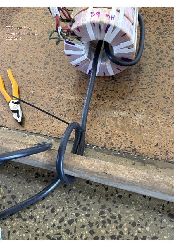 No stone unturned, no FET unburned. |
||||
| Page 1 of 8 |
|||||
| The Back Shed's forum code is written, and hosted, in Australia. | © JAQ Software 2026 |
