Notice. New forum software under development. It's going to miss a few functions and look a bit ugly for a while, but I'm working on it full time now as the old forum was too unstable. Couple days, all good. If you notice any issues, please contact me.
Grogster Admin Group Joined: 31/12/2012 Location: New ZealandPosts: 9986
Posted: 05:15am 13 Mar 2025
Copy link to clipboard
Print this post
Hi all.
Plenty of US$5 modules on AliExpress that switch a relay based on a preset current limit, but they are all for AC current. I need a similar thing, that will trip a relay when a preset amount of DC current is exceeded. Anyone got any links to modules or even schematics they can share?
Current limit of about 2A @ 24vDC is plenty, but anything LESS then that, the relay stays off. Using the NC+COM contacts, if the current is exceeded, the relay trips, and the NC+COM circuit is interrupted.
It needs to then STAY in the tripped state, till the power is cycled - I don't want it to drop the relay back out again, if the current drops below the preset limit.
That is probably easiest to achieve with a simple SCR driving a relay - which will then keep the relay in the tripped state till you remove the power. So then all I need is some kind of simple current-sense arrangement in front of the SCR.
Anyone got any bright idea? Edited 2025-03-13 15:16 by GrogsterSmoke makes things work. When the smoke gets out, it stops!
phil99 Guru Joined: 11/02/2018 Location: AustraliaPosts: 3317
Posted: 07:51am 13 Mar 2025
Copy link to clipboard
Print this post
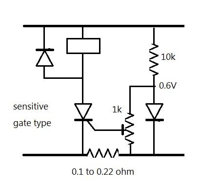
If the current shunt can be in the negative line this is quite simple. The voltage across the shunt is added to the voltage divided by the pot from the 0.6V reference. When the sum reaches 0.6V the SCR switches on. If the shunt needs to be in the positive line add a PNP transistor to feed down to the gate. I can draw it up later if you need that. Edited 2025-03-13 17:56 by phil99
Footnote added 2025-03-13 19:58 by phil99 I forgot about the starting current, that will trigger the SCR. Add a capacitor from gate to cathode. Try 10µF first and increase until the motor starts reliably.
Grogster Admin Group Joined: 31/12/2012 Location: New ZealandPosts: 9986
Posted: 08:04am 13 Mar 2025
Copy link to clipboard
Print this post
Just to complicate things, it needs to operate with EITHER polarity.
The circuit is driving a DC motor, that is operating a liner drive. When it gets to the end of its travel and the motor basically stalls cos it can't drive it any further, the circuit then detects that and isolates the motor supply.
If the input polarity then reverses, the linear drive reverses - till it reaches the end of travel, and the current spikes again due to the motor being stalled.
....and the relay cuts out again.
I am studying the original PCB now, but it will take a few daze to transcribe it to some kind of schematic that I can post here...Smoke makes things work. When the smoke gets out, it stops!
phil99 Guru Joined: 11/02/2018 Location: AustraliaPosts: 3317
Posted: 08:14am 13 Mar 2025
Copy link to clipboard
Print this post
If the current sensing is on the supply side of the reversing relay or H-bridge the polarity will always be the same.
Edit. I forgot about the starting current, that will trigger the SCR. Add a capacitor from gate to cathode. Try 10µF first and increase till it starts reliably. Edited 2025-03-13 21:54 by phil99
Grogster Admin Group Joined: 31/12/2012 Location: New ZealandPosts: 9986
Posted: 11:12pm 13 Mar 2025
Copy link to clipboard
Print this post
Thanks very much Phil, something to study in the meantime. Smoke makes things work. When the smoke gets out, it stops!
phil99 Guru Joined: 11/02/2018 Location: AustraliaPosts: 3317
Posted: 11:58pm 13 Mar 2025
Copy link to clipboard
Print this post
An alternative that replaces the SCR with a NPN. Latching action is provided by positive feedback from NPN collector to PNP base. The extra diode in the feedback might not be needed. Edited 2025-03-14 10:05 by phil99
Grogster Admin Group Joined: 31/12/2012 Location: New ZealandPosts: 9986
Posted: 12:53am 14 Mar 2025
Copy link to clipboard
Print this post
Owwww - this one is interesting, and is starting to look similar to what I have managed to draw from the original PCB module that has gone fluffy.
It's all tiny SMD though, so it is quite hard to translate the small PCB, to a schematic so I can study what is going on, but your circuit there might be a variation of what I am seeing here.
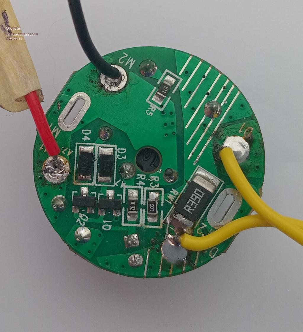
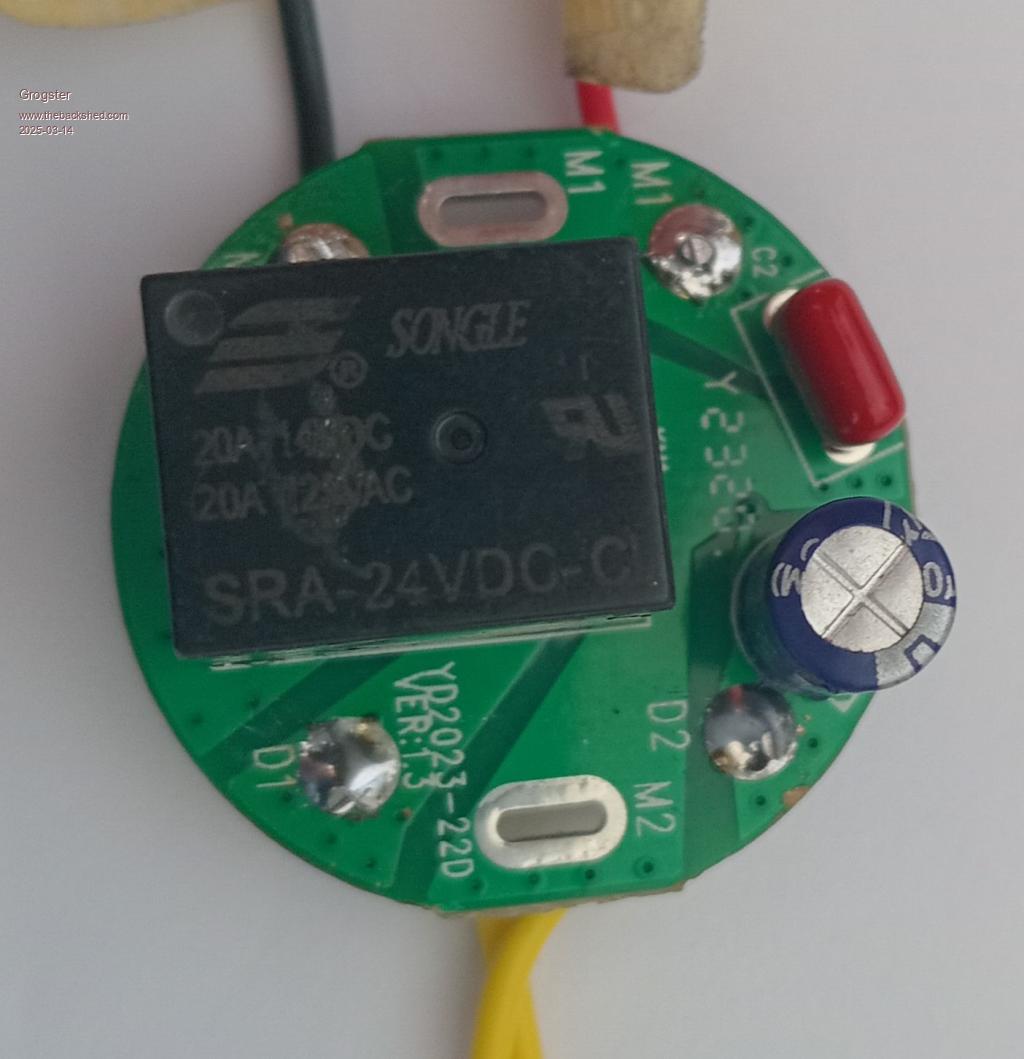
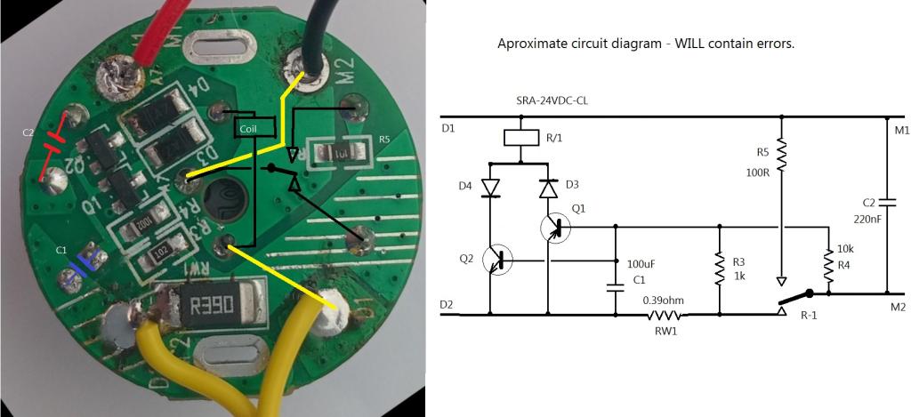
Here are two photos of the wee module I am trying to draw out:
Yellow wires are the 24v DC in - it can be either polarity. One polarity drives the motor in one direction, reverse the polarity and the motor goes in the other direction.
Either way, when the current spikes, the relay disconnects one of the wires to the motor.
I've tried searching for this thing using the PCB markings, but did not get any hits.
The blue electro is 100uF/35v, the red poly is 220nF directly across the motor as some form of suppression.
The fault with this module, is that as soon as you apply power, before the motor even starts to move the linear thing, the circuit trips and the motor gets disconnected. This happens 95% of the time. There are the odd times where it DOES work as should - the motor starts, runs to the end of travel, stalls, and THEN the relay disconnects the motor - that is how it is supposed to work, but at the moment, most of the time it just trips when powered, so the current sense is wrong/not working/has changed/component values have aged etc...
No-load run current is only about 100mA @ 24v Stall current is about 2.5A, which is when the relay is supposed to come into effect. Edited 2025-03-14 11:03 by GrogsterSmoke makes things work. When the smoke gets out, it stops!
Godoh Guru Joined: 26/09/2020 Location: AustraliaPosts: 675
Posted: 01:12am 14 Mar 2025
Copy link to clipboard
Print this post
Hi Grogster, why not just use a limit switch at each end of the travel. A micro switch that operates a relay is all that you would need. Lots of cranes used to have limit switches to stop the motor when the crane was at either end of its travel or lift. Pete
Grogster Admin Group Joined: 31/12/2012 Location: New ZealandPosts: 9986
Posted: 01:20am 14 Mar 2025
Copy link to clipboard
Print this post
I agree, and that is the more standard thing I have seen, but this linear drive thing simply does not do it that way, and there is no way you could ever fit them inside due to the small size of the drive enclosure, so I have to have an over-current cutout kind of arrangement similar to the original module that is playing up.
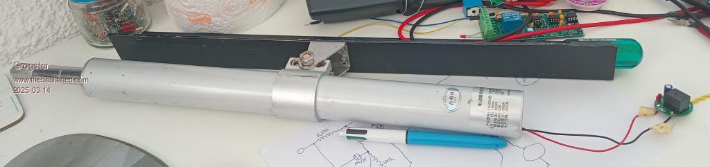
Here is a photo of the linear drive thing:
Smoke makes things work. When the smoke gets out, it stops!
phil99 Guru Joined: 11/02/2018 Location: AustraliaPosts: 3317
Posted: 03:06am 14 Mar 2025
Copy link to clipboard
Print this post
As near as I can see from the photos D4 cathode goes to Q2 collector and D5 anode goes to Q1 collector so Q2 must be NPN and Q1 PNP. The other ends of the diodes go to supply D1 and to a relay contact. Another relay contact goes to motor M1.
The two bases are tied to each other, same for the emitters which go to the relay coil via 100Ω. The 0.39Ω is the shunt and goes from supply D2 to motor M2. The other end of the relay coil also goes to M2
The 100µF goes from supply D2 to the bases. The polarity of the voltage across it will depend on the supply polarity so a non-polarised type would be better. The voltage across it probably never exceeds 1V so they have been able to get away with it for a while. I would check that cap. or just replace it. Perhaps replace it with two 220µF in series, positive to positive to create a 110µF non-polar.
Another possibility is too much starting current. Maybe the motor bearings and drivetrain need lubricating.
Edit Had a closer look at the way the relay contacts appear to be connected. I think the NO contact feeds back to the bases to provide the latching. If that is the case C1 could have a significant reverse voltage on it so I think it is likely to be the problem. Edited 2025-03-14 15:11 by phil99
Grogster Admin Group Joined: 31/12/2012 Location: New ZealandPosts: 9986
Posted: 01:01am 15 Mar 2025
Copy link to clipboard
Print this post
Great, I will replace it as a first move. I will use a non-polar electro, if I have one, or your idea of a couple of 220's in series if I don't have a suitable non-polar one.
I did remove the wires to the motor, and powered the motor directly with the bench supply, and it springs to life without any sign of having trouble getting going, but put the wires back on the module, and the motor TRIES to start for about half a second, then the relay kicks in and stops the motor.
I will replace the cap, and let the thread know what happens. Smoke makes things work. When the smoke gets out, it stops!
phil99 Guru Joined: 11/02/2018 Location: AustraliaPosts: 3317
Posted: 01:17am 15 Mar 2025
Copy link to clipboard
Print this post
That the motor "springs to life without any sign of having trouble getting going" on the bench supply and suggests the problem may be with the control module. The delay suggests the cut-out is working as it should, allowing time for the motor start current to fall before tripping. If the motor isn't getting enough voltage to get started it will continue to draw a high current.
Connect the control module directly to the motor and monitor the voltage and current at the motor. If it starts reliably I am wrong and back to Plan A.
Edit Another thing to check on the current cut-out is the resistance of the relay contacts, D1 to M1 I think. On the top photo the relay conceals the tracks so you will need to check where they go with a meter. Edited 2025-03-15 20:46 by phil99
phil99 Guru Joined: 11/02/2018 Location: AustraliaPosts: 3317
Posted: 04:07am 16 Mar 2025
Copy link to clipboard
Print this post
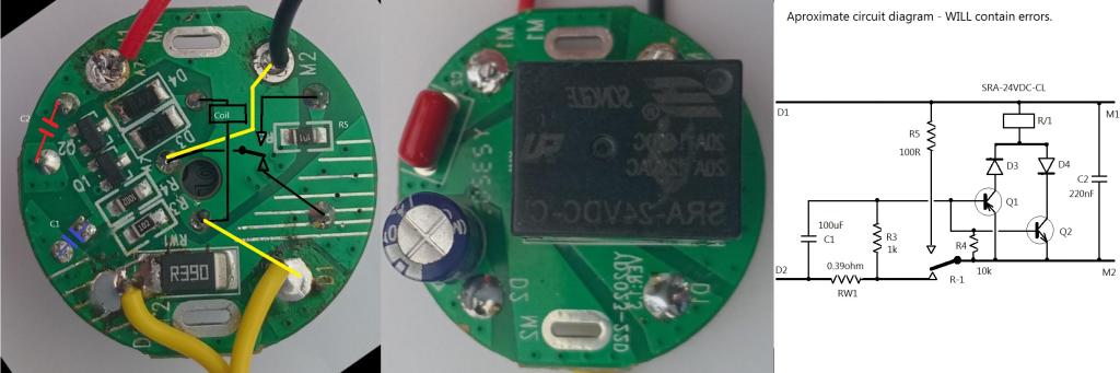
Had another go at tracing the circuit. Without being able to probe the board there will be errors. Even more certain C1 needs to be non-polar. Does terminal D2 connect to the negative end of C1?. It is hard to see if there is a solder fillet or a gap near the D2 wire.
Do both emitters connect to M2?
Edit I suspect you need to swap C1 and R4 in the diagram, or more likely, the emitters go to D2 not M2. I don't think it will work as it is currently drawn.
Edit 2 I think this version has a better chance of being correct. Edited 2025-03-16 15:20 by phil99
Grogster Admin Group Joined: 31/12/2012 Location: New ZealandPosts: 9986
Posted: 04:32am 16 Mar 2025
Copy link to clipboard
Print this post
WOW - above and beyond, Phil - thanks a bunch! I had STARTED to draw it out, but got distracted with other things.
I have to pop away for something right now, but when I get back, I will probe those things, and post the result here.Smoke makes things work. When the smoke gets out, it stops!
Grogster Admin Group Joined: 31/12/2012 Location: New ZealandPosts: 9986
Posted: 04:43am 16 Mar 2025
Copy link to clipboard
Print this post
Both emitters ARE connected together(zero ohms on diode-test function), but they are then connected to D2.
NOT M2.
D2 DOES connect to the negative of C1. Edited 2025-03-16 14:45 by GrogsterSmoke makes things work. When the smoke gets out, it stops!
phil99 Guru Joined: 11/02/2018 Location: AustraliaPosts: 3317
Posted: 05:33am 16 Mar 2025
Copy link to clipboard
Print this post
Was doing edit 2 when you posted that. See new circuit in Edit 2 above.
Grogster Admin Group Joined: 31/12/2012 Location: New ZealandPosts: 9986
Posted: 06:00am 16 Mar 2025
Copy link to clipboard
Print this post
Excellent, thanks a bunch. Smoke makes things work. When the smoke gets out, it stops!
phil99 Guru Joined: 11/02/2018 Location: AustraliaPosts: 3317
Posted: 06:22am 16 Mar 2025
Copy link to clipboard
Print this post
As C1 is across the B-E junctions it will never have more than 0.7V so a 100µF 6.3V non-polar or 2 x 220µF 6.3V back-to-back polar should be small enough to fit, if that is the problem.
Relay contact resistance or a problem with the control module are also possible.


 If the shunt needs to be in the positive line add a PNP transistor to feed down to the gate. I can draw it up later if you need that.
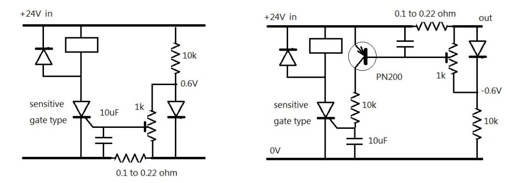

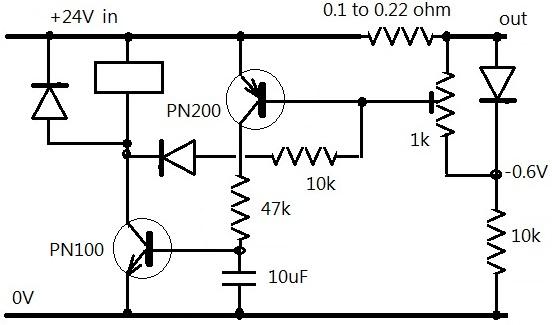 The extra diode in the feedback might not be needed.