
|
|
Forum Index : Electronics : Used Tie Grid inverter -Interesting Design
| Author | Message | ||||
| oreo Senior Member Joined: 11/12/2020 Location: CanadaPosts: 133 |
I am normally on the lookout for scrap inverters, but normally do not run into much around here (Canada). Recently I saw a Tie grid inverter that looked interesting. Looking up the specifications it's rating is: MPPT input voltage 54-95VDC 208VAC 5kw continuous 63Kg weight, 10yr warranty standard, 20yr warranty optional No one would want this, since residential supply here is 240v split phase not 208 and this inverter is 14yrs old. It has a real low MPPT input voltage range, and since my battery is 72v nominal the transformers might actually work for me (not that I really needed more transformers, but anyway that's not the point right?). So I got an good price and brought it home yesterday. It has an all aluminum chassis and is made up of: An input capacitor board with 25pcs of 3900uF 160v 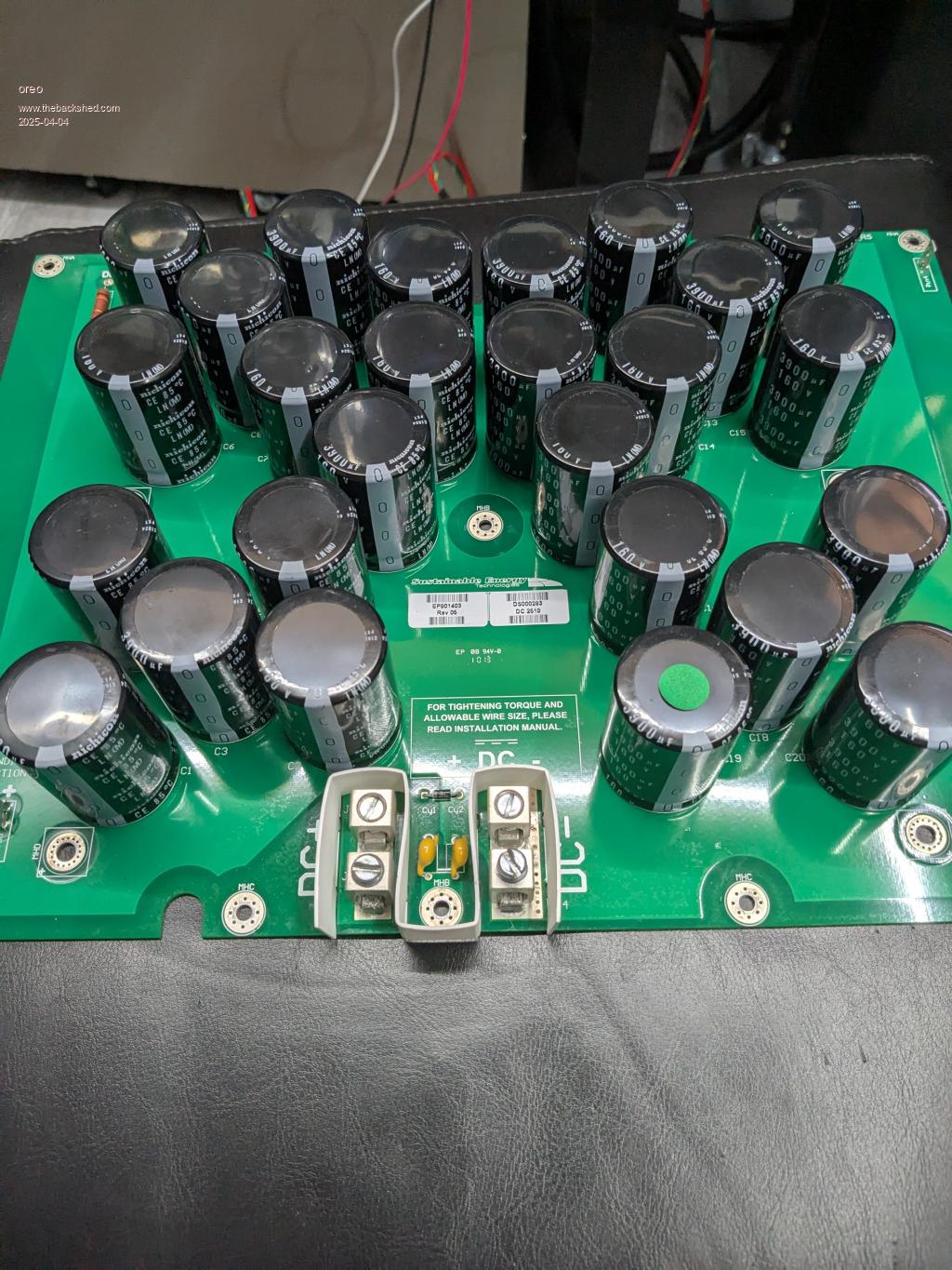 A board with 4 inverter sections, each using 4 sets of 4 150v 180a mosfets. 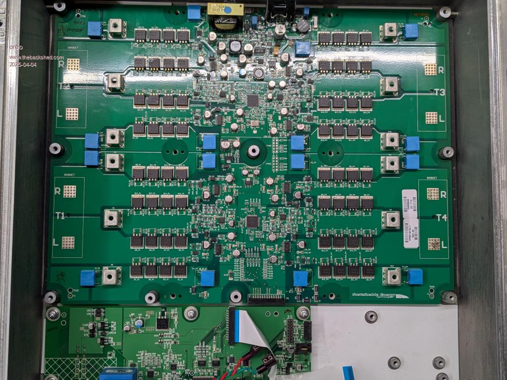 And a transformer section with 4 toroid transformers and 2 1mH chokes and a filter board. 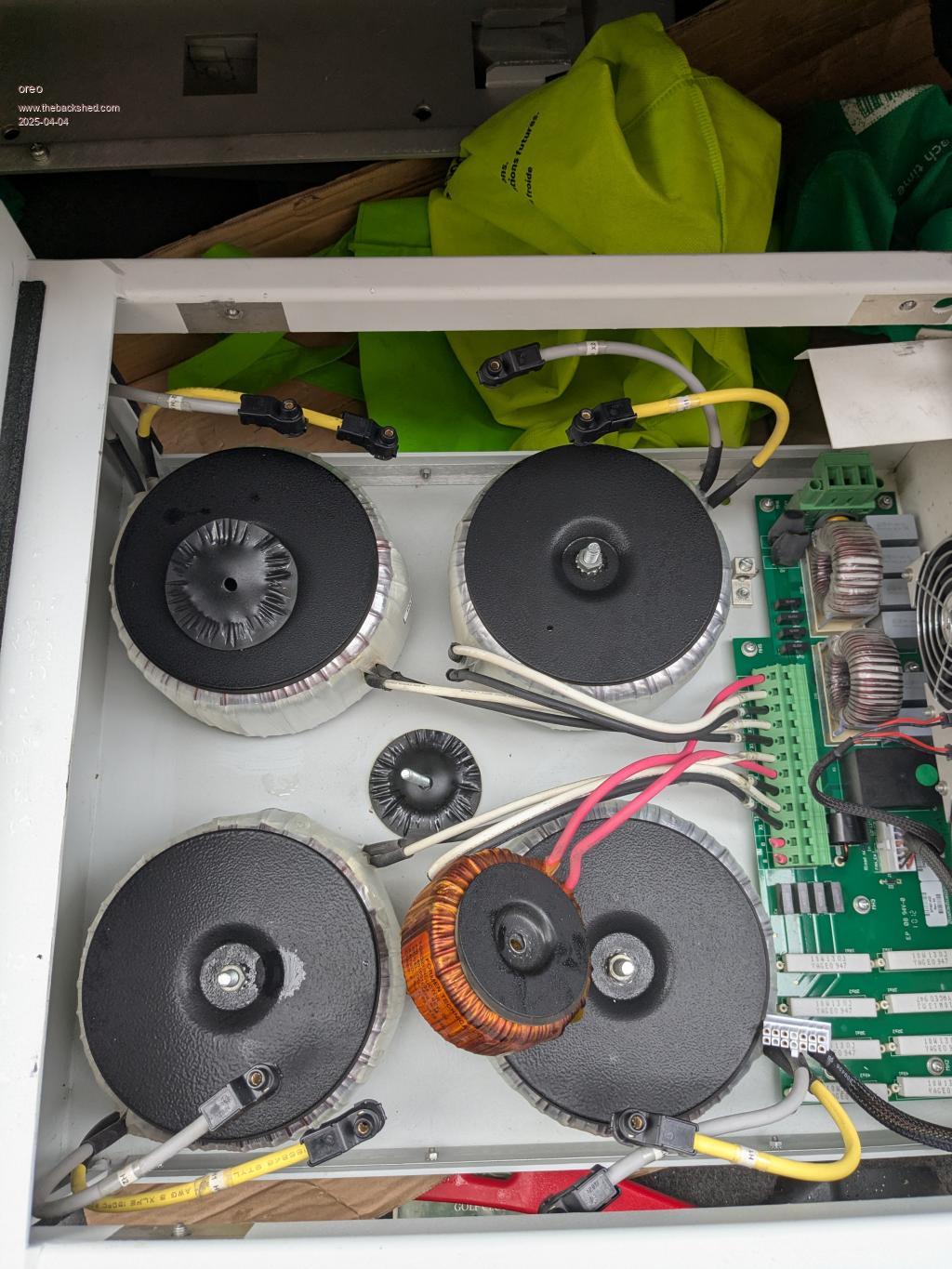 Greg |
||||
| oreo Senior Member Joined: 11/12/2020 Location: CanadaPosts: 133 |
And now the interesting part (s). 1. There are 4 separate inverters (ok, maybe not that interesting) 2. The transformer outputs are connected in series (not parallel) 3. Between the inverter output FETs and the Transformers, there are no inductors! I jotted down a block diagram/schematic. 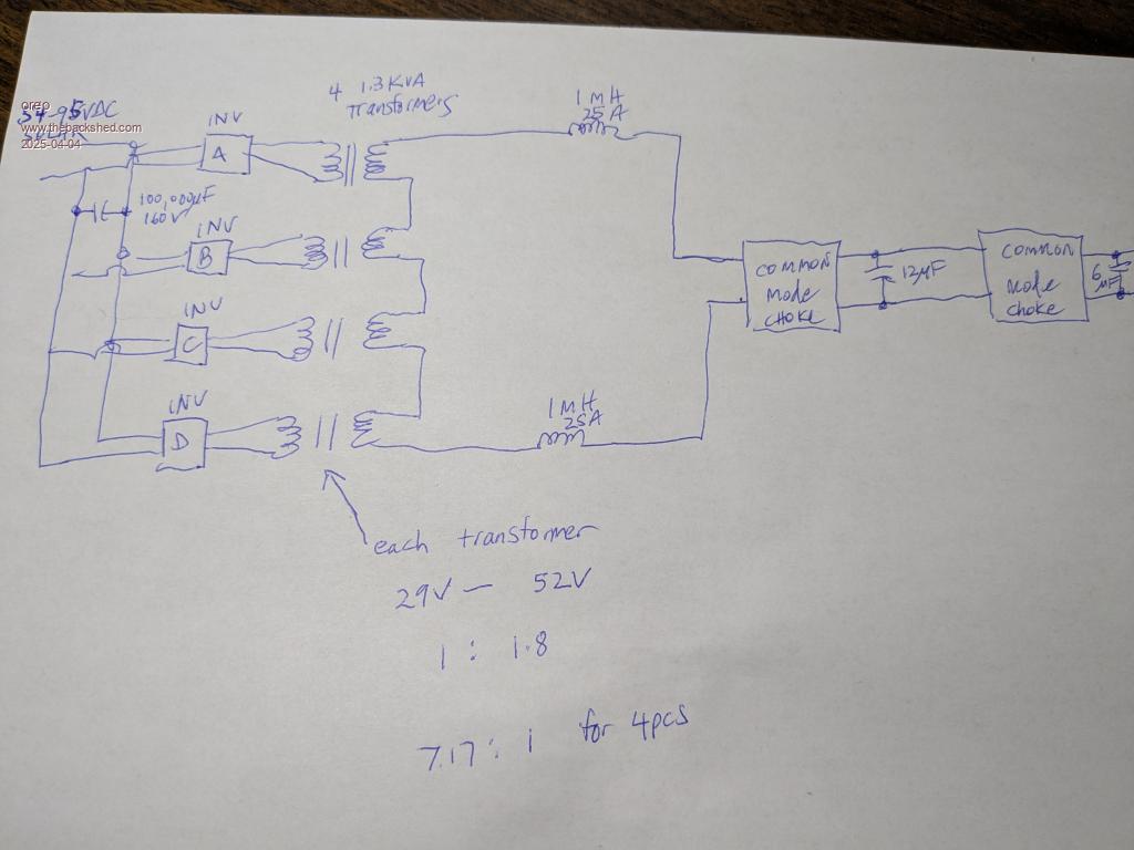 So they put the inductors after the transformers but before the filter capacitors. I have not see this before. Maybe it only works with smaller power transformers IDK. Thoughts? Greg |
||||
| Godoh Guru Joined: 26/09/2020 Location: AustraliaPosts: 675 |
Wow Greg, lots of good parts in that box. If you have plenty of time on then unwinding the transformers and stacking the cores would give you a pretty good transformer for a home made inverter when it was rewound. Also lots of useful capacitors and the box have fun pete |
||||
| wiseguy Guru Joined: 21/06/2018 Location: AustraliaPosts: 1297 |
Thanks for this post Greg it confirms my theory about this. I am aware that in our inverters with a primary choke, if the mains output capacitor is not used then there is almost no current draw from the source supply. Looking at the secondary voltage with a CRO under this condition reveals that the 19KHZ fundamental is passed through the toroid with minimal loss. I had a discussion about a year ago with Tony/Poida/Roger? (cant remember now) about this exact theory and using a secondary choke is on my list to play with. The ultimate reason was much thinner wire required, as current in the secondary is about 1/8 of the primary, but conversely the voltage is 8 times higher so more turns required, but luckily this is a squared law so not 8 times the number of turns required. The inverter you have shown pictures of is the internals I saw recently from a large auction here where about 50+ inverters were sold for $50 each, Roger & I pulled one down to see the internals - the same as yours. But the transformers were not part of the inverter and were sold separately by the pallet. I remember commenting to Roger that the chokes (also sold separately) were way too high in value to be primary chokes, your post suppled the definitive answer! So thanks for filling in the missing links, the inverters were not sold whole but as separate lots/components towards a complete inverter, if you knew what to do with them. BTW I picked up a 12KW SolArk brand new for $301AUD at that auction, it is a hybrid type that uses nominal 48V, it has Auto changeover from Mains and it can throughput 12KW from the mains but supplies only 9KW from the battery/inverter. A real beast that can have a separate generator input and can also charge at over 100A If at first you dont succeed, I suggest you avoid sky diving.... Cheers Mike |
||||
| oreo Senior Member Joined: 11/12/2020 Location: CanadaPosts: 133 |
Haha absolutely! Mike I looked up the spec's and price on the Sol-ARK 12K hybrid and you got yourself a fantastic deal and a very nice machine. Well done! I understand your logic on the inductor position. I threw one of the 1mH/25A inductors on my saturation tester, and it saturates pretty hard at 36amps. Honestly, the inductor selection is a bit of a mystery for me right now. After reading a lot on this forum, I see that over the years the design thinking on what the core should be has changed. A number of years ago it was #1 and today it is #3. 1. Gapped Amorphous Nanocrystalline cores (Aero-sharp) measured so they absolutely won't saturate while in operation. (note I am guessing the makeup of these cores based on description) 2. Gapped ferrite measured so they absolutely won't saturate while in operation. 3. Sendust (Kool Mu) toroidal cores I have been using the Micrometals design tool, "Inductor Analyzer" to run simulations on multiple core sizes, materials (Iron powder and Sendust) and stacking, to see what the effects are. I have built 3 different chokes using a 3 stack, a 4 stack and a 5 stack, and measured the inductance at different currents on my saturation tester and have found that the program mirrors what I am measuring in real life. (Eureka) You probably already know this, but here are some of the results. What happens when you use a core with 60 vs 125 permeability. (You get more inductance per turn with the 125, but if both cores start at the same inductance, the 125 perm unit will have less inductance at 100 amps. 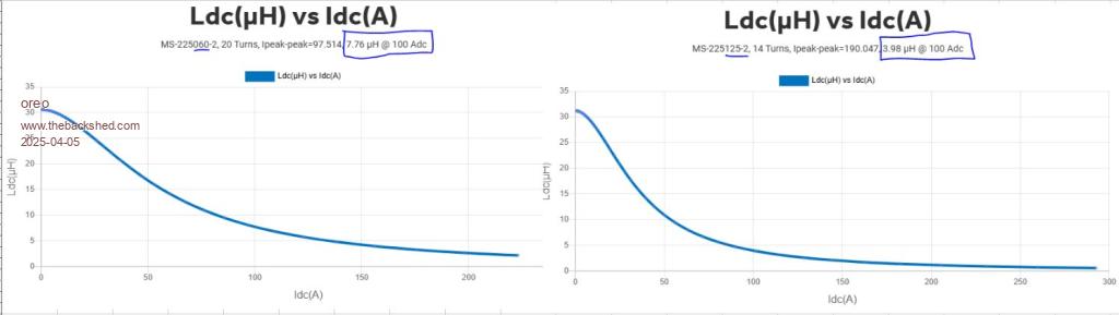 What happens to saturation when you stack cores and keep the same inductance. (As you add cores, the saturation improvement becomes less. With 1 core you have 4uH/core, with 2=3.5uH/Core, 5=2.5uH/core and 10=1.7uH per core) 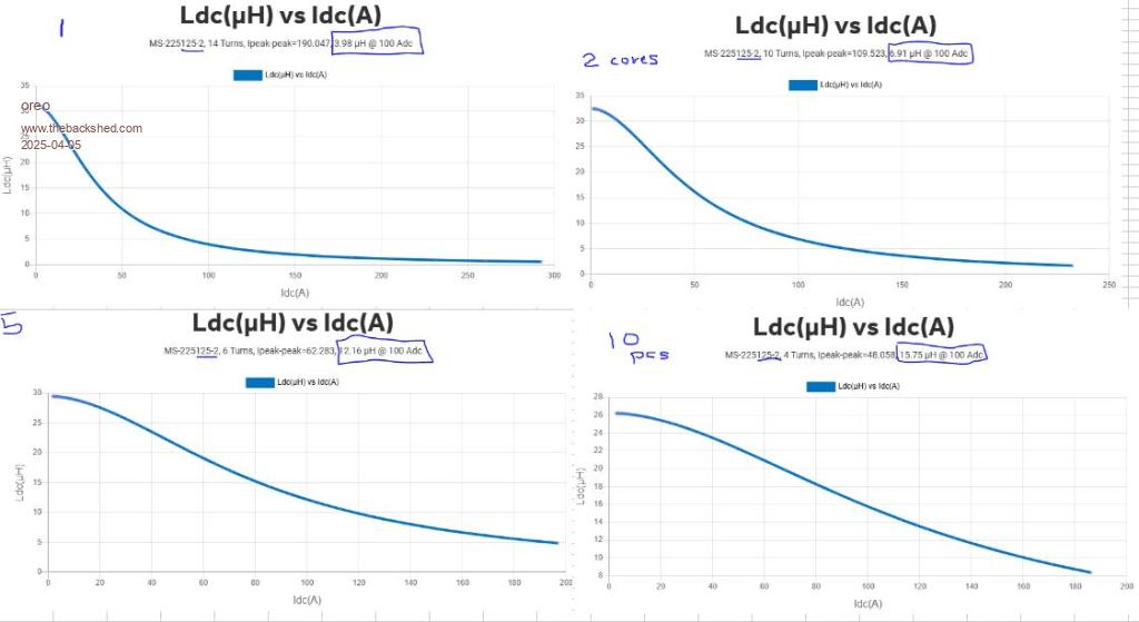 If you are doing this with 40 permability cores, it gets worse. With 1 core you have 4uH/core, with 2=3.0uH/Core, 5=1.7uH/core and 10=1.2uH per core) Note that after I ran these simulations, I realized I had the frequency set wrong. Setting it correctly changed the ripple current, but not the inductance. (less than 1% change) Greg |
||||
| oreo Senior Member Joined: 11/12/2020 Location: CanadaPosts: 133 |
maybe that was a bit overboard, but anyway back on track now. So if we look at Keepis build (also Mike?) we see he is using stacks of 9 pcs of A225125 cores (MS-225125-2 equivalent) Here is what this looks like in "Inductor analyzer". 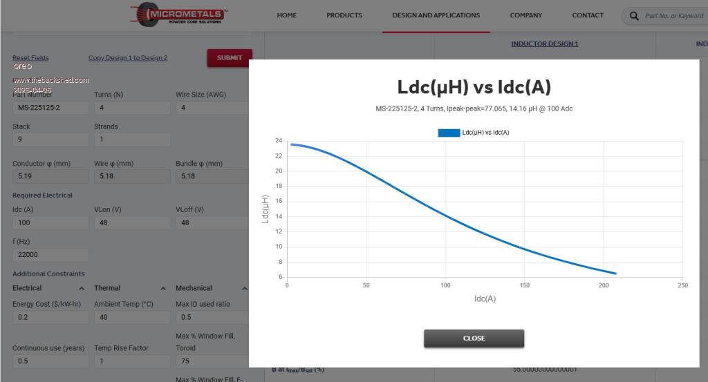 Now I understand that he has a mixture of cores being used, with some MS-226 sized cores which are 1mm larger in diameter and with a 10mm smaller ID, but largely these only measure slightly better than the above. So Keepis is running his inverter with up to 400 peak amps. At 200 amps he has about 7uH x2 =14uH. At 400 amps he has about 5uH. That is not much, and his system has been running like a top. Any thoughts on why this is? 1. Maybe full saturation is really bad, but near total saturation is ok? 2. Maybe the new inverter design is so robust that having low inductance at high currents won't kill it? 3. Maybe the toroid design used by Keepis is less inductor dependent? (I read that the amount of transformer coupling there is can affect inductor requirements, but am unsure if the way they are stacked results in less coupling or not) For my intended upgrade, I need something on the inductor front. I found some 90x60x20 Amorphous Nanocrystalline toroid cores on Ebay, which if gapped at 1.2mm and 2 groups are used stacked 4 up will result in a saturation current of >200A with 60uH (72v Battery). I would need to buy 4 more cores so another $18usd to get them into Canada. Amorphous core sold as "Ferrite" Alternately I see some cores on Alibaba, similar to the ones Dex has used. These are slightly smaller (MS-520075-2) at $10.40us each (min 1). Using 2 stacks of 2 would result in 60uH, dropping to 30uH at 200A. Alibaba is saying my first order would ship free, but IDK. Pretty massive Sendust cores Or maybe TOFTT and run secondary inductors which I already have? Greg |
||||
| Murphy's friend Guru Joined: 04/10/2019 Location: AustraliaPosts: 678 |
Something about the chokes used with the inverters built here may be of interest to a few forumites. I have been experimenting with different chokes ever since I started building inverters. One thing I learned is that if the battery gets back charged through the inverter (from an independent GTI) then *any* choke with an air gap is going to be noisy. Some were annoyingly loud. All that changed when KeepIS came up with the idea of using Sendust ring core chokes. These are absolutely silent, even if I back charge 100A from my GTI. So now all my inverters have been changed for these and I have a nice selection of sintered silicon chokes (ex Aerosharp cores) sitting in a box  |
||||
| KeepIS Guru Joined: 13/10/2014 Location: AustraliaPosts: 2196 |
Along with the smaller Choke inductance at high currents, the lenght of each choke winding combined with using slightly smaller gauge cable. This results in an additional small resistive loss at normal running loads, but one that really comes into play under very high current short duration events, thus helping the FETS survive switching into the extremely low impedance Toroid primary. I may have to do some measurements on my test setup and try secondary chokes and a filter. I'm sure if Wiseguy gets the time he likely will do the same, just need to find the time. BTW with the dual inverter load currents are halved, 400A with two power stages each stage with two chokes and each handling 200A. EDIT: There is no coupling and the choke works exactly the same on a single Toroid, and is also the correct (sweet spot) value for that single Toroid.  . Edited 2025-04-05 16:09 by KeepIS NANO:Inverter V 8.2ks - Linux AvrDude GUI script V4.1 |
||||
| oreo Senior Member Joined: 11/12/2020 Location: CanadaPosts: 133 |
Thank you for this useful back ground information. I had to do a little reading on what "back charged" means. So I gather that for a standard inverter (not grid tied), a gapped core does not make this noise? Greg |
||||
| oreo Senior Member Joined: 11/12/2020 Location: CanadaPosts: 133 |
oops, I must have misread that. (I really wanted you to be pushing 400a through each power stage though!) Anyway so with 200amps, your inductance is at a much more reasonable value of about 14uH. Ok so this is making more sense. Thanks for your comments! Greg |
||||
| wiseguy Guru Joined: 21/06/2018 Location: AustraliaPosts: 1297 |
Greg FYI I ran some calculations on the KeepIS chokes and this is what I worked out. I was looking at their values at around the Bsat point but note the Bsat was at 400A for the blue but only ~ 200A for the black ones. 2 x blue stacked 276Al, Ae= 4.5742sqCM = 4.4uH for 4Turns and 415A at 1T Bsat 4 x Black stacked Al=1148 Ae=9.1484sqCM = 18.5uH for 4Turns 198A at 1T Bsat Intuitively a total of 22.9uH @ 198A @1T reducing to ? at 415A a bit more than 4.4uH a lot less than 22.9uH As you have two of these the 22.9 doubles to 45.8uH @ ~200A, but reducing to maybe 10 to 15uH at ~ 400A I did these calcs quite a while ago, it is not too dissimilar to your work despite the inductance being higher for when he was running 6 cores not nine, so why were they not higher for nine? My Al values were for Molypermalloy (MPP) which are normally Blue, for the Black I used KoolMu data. After re-reading this not sure if it is helpful or not.... Edited 2025-04-06 10:10 by wiseguy If at first you dont succeed, I suggest you avoid sky diving.... Cheers Mike |
||||
| Murphy's friend Guru Joined: 04/10/2019 Location: AustraliaPosts: 678 |
From my experience, gapped choke cores hum a little, which increases with power drawn and could be managed to tolerable by very secure core halve clamping. Back charging changed this hum to a growl. But these inverters were never absolutely silent as mine are now with the ring core chokes. |
||||
| The Back Shed's forum code is written, and hosted, in Australia. | © JAQ Software 2026 |
