
|
|
Forum Index : Electronics : Radio telemetry
| Page 1 of 2 |
|||||
| Author | Message | ||||
| GWatPE Senior Member Joined: 01/09/2006 Location: AustraliaPosts: 2127 |
I did a quick search for a previous thread on telemetry, but decided to start a new one. I have revisited the 433MHz Rx/Tx units from Oatley. I thought the ones I had were damaged, so stopped my experiments. I had a request for a wireless COMM system for battery monitoring. The biggest difficulty was choosing the best data format. I settled on single word transmission with a double reading/comparison on the reciever end, with unique data string identification per word. The Rx had difficulty decoding multiple words somehow. Have ended up with error free data transmission, and the ability to recieve multiple data sets from different transmitters, or the same transmitter. I have plans to include testing of wireless piclog data transfer as well. So far 100m is about the limit, LOS. I will be looking at better antennae. I intend to adapt the logging program that I made and posted several years ago to use RF wireless inputs, to overcome ground loop problems, with current measurements. The wireless aspect and error free transmission/reception are aspects that I was having problems with in the past. My prototype is a universal, 12V, 24V, 48V autosensing battery charge status indicator. This has a 5 LED display, with different indication methods for the various battery conditions. I wanted to give a simplified indicator, to a digital voltage readout. Many RE punters only want a guide, rather than a digital number. I have yet to adopt battery saving mode, to only power the Tx during data transfer. I hope to reduce the average consumption to a few mA. The Rx runs off a plugpac from normal house GPO. What maximum range have readers achieved from these 433MHz type units? I have 2 pairs of full duplex units Rx/Tx in same unit. I may end up using them just as additional transmitters. These are 3V devices, so are more difficult to adapt to the 5V picaxe logic. May need to look at the 3V versions. Gordon. become more energy aware |
||||
| davef Guru Joined: 14/05/2006 Location: New ZealandPosts: 499 |
Gordon, Is that the RX14 (ASK), which is basically ON/OFF keying? There has been quite a bit of traffic on AVRfreaks.net re different types of RF modules. Might be worth a scan. As I recall there are issues with simple keying systems and getting reliable data throughput. Preambles are used on many of these systems to get the reliability up. Also, Manchester encoding is used on a lot of them to get around DC shift issues in the receiver. Supply a few more details, ie modulation format and .pdfs if possible. Sending the data multiple times is certainly a method of guaranteeing you have correct data and for low data rates probably a good solution. |
||||
| davef Guru Joined: 14/05/2006 Location: New ZealandPosts: 499 |
Just had a good look around www.futurlec.com at their RF RX and TX offerings by Hope RF. Some good data sheets. I think I have seen someone in Australia selling these parts as well. I see one the .pdfs claim they can handle as low as 3 bytes of data. Happy hunting! |
||||
| GWatPE Senior Member Joined: 01/09/2006 Location: AustraliaPosts: 2127 |
Hi davef, The Tx module is about 12mm x 12mm, 4pin DIP, serin,Gnd, 5V and Txout. the Rx is 5pin SIP package, Rx,Rxgnd,Gnd, serout and 5V. Fixed 2400 baud, 1S8bit1S type format I think. The data may be 16bit though. I haven't looked at the data stream with a CRO. These units seem OK for small amounts of data. The qualifier string I use is 4bytes. I am only sending small quantities of data with a 500mS update rate, so nothing really out there. The new 433.92MHz full duplex modules are programmable baud rate, up to 19200. Low end is 2400 baud. They are DR3000's, made by RFM. These have provisions for ASK[amplitude shift keying], as well as OOK[on/off keying] type coding. The trial unit is fully functioning, with the intended operation. I was only hoping to extend the range a bit. I could not see the units I have on the futuretec site. The encoding is performed by the picaxe serout command. The decoding is performed by the picaxe serin command. No point in making things complicated. Manchester encoding may be part of the process, but I haven't seen it mentioned. As I said above, I was really after a bit of extra range. I will be looking at a better antennae. Gordon. become more energy aware |
||||
| davef Guru Joined: 14/05/2006 Location: New ZealandPosts: 499 |
The datasheet for the DR3000 says 916.3MHz. Looks like an antenna is connected to pin 13. What are you using for an antenna at the moment? Antenna choices . . . depends on whether you want omni-directional or directional antennas. A couple of 10dB gain Yagis at both ends would sure boost the range. Cost and size might change that approach. A 1/4 wavelength ground plane antenna is easy to make. Had to check on Wikipedia as I didn't know that there was a difference between ASK and OOK. Appears that some ASK systems can use multi-level carrier, ie OFF , 1/2 ON and ON (etc.) Think you would need a pretty constant path loss to get reliable comms with multi-level ASK. As RFM is high-technology supplier I would expect some application notes for using these devices. RX sensitivity is reasonable but TX power is under 1mW. There is enough information there to run a "link budget" program, which I could do at work to give you some estimate on range improvement with different antenna systems. Dave |
||||
| GWatPE Senior Member Joined: 01/09/2006 Location: AustraliaPosts: 2127 |
I have not had any success with the full duplex units. These will probably need an initialization stage. The data sheets say that they have to be started in reciever mode, then the mode can be changed. This will be a job for a dedicated micro test unit. The dedicated units I am currently using are still available from OatleyElectronics, so I will be ordering some more[ TX01, and PVJ6WC ]. I realize now, that there will be problems with multiple transmitters within close proximity. This will make decoding difficult at the reciever end, so will look at other options. The pair I have are working well. I would not use this system where timing is critical. The general battery status indication is an ideal use. I have been able to incorporate the Tx code into the controller I had been working on for my own system. The unit now controls the windmills and transmits the battery status inside to the visual display. I will be able to remove the hard wired battery loom running inside, from the battery room outside. The latest Tx modules, have a simpler connection and will integrate easily into any projects. A higher power unit available has a single wire pre attached antennae. Claims of several km range were stated. I will continue working on the dedicated units. The multiple data packet transfers need to be longer, so this will be my next project. Gordon. become more energy aware |
||||
| davef Guru Joined: 14/05/2006 Location: New ZealandPosts: 499 |
*** I realize now, that there will be problems with multiple transmitters within close proximity. This will make decoding difficult at the reciever end, so will look at other options. *** The way to get around this issue is for you have a master control end and the rest are slaves or outstations. Then you poll the outstations. They probably only need to transmit status information every 10 seconds or minute anyhow. Of course the master end has a controller attached to it, but maybe the slaves wouldn't need much in the way of smarts. The slaves would all be in RX mode until the master said I want some information from you. Then they can switch to TX. Maybe some simple logic circuitry could do that. Have fun. Dave |
||||
| GWatPE Senior Member Joined: 01/09/2006 Location: AustraliaPosts: 2127 |
The Radio units are not really as good as one would like. I have checked the data stream captured by the reciever for std qualifier,data transmission. Most of the data transmitted is not successfully received. Enough of the data pairs get through to claim a successful system. I have revised the transmission system and have included an extra few bits just prior to the data packet, to allow the reciever to lock into the transmitter. I have used 1100 as the signal. The receiver waits for the input RS232 signal line to stay high. The receiver then looks for the qualifier string, and then accepts a data string to a register. This sequence is repeated for the second check data stream. The receiver is now only looking for the data stream during an accurate timing window. The system becomes synchonized, as opposed to being hit and miss asynchronous. The transmitter is still free running, but the reciever now waits and locks onto the start of the data stream. There are now some slight timing gaps, but more valid data packets are captured. I am not sure how many other interfering systems exist in a typical home environment. I would have thought that at 2400 baud, there would be close to 100% capture. Wires will still be my choice for a more ctitical system. I have a lot more testing, but this will have to be with a more controlled system. Have to wait for my order to arrive. Gordon. become more energy aware |
||||
| GWatPE Senior Member Joined: 01/09/2006 Location: AustraliaPosts: 2127 |
I have had more mixed results with the generic 433MHz receivers from Oatleys. I noticed that there appeared to be a cyclic nature associated with the reception quality. I had to make a new signal quality test unit. I used one of the tranciever units, as a reciever only. This turned out easier than expected. A single red LED in the RX + power supply line was enough to drop the 5V down to the suitable voltage from the plug pack. The units do fire up in receiver mode, with config pins held high. The OatleyElectronics TXonly unit is programmed to send an additional nibble just prior to the main data string. This is a free running system. At a 1 second time interval, the program reads the variable, and then transmit it twice, as a decimal number. In this 2 step process, a different qualifier string for each transmission is sent, prior to the data. The picaxe input pin had enough signal level to read the data stream from the tranciever operating at approx 3.3V. I have overcome most of the reception problems by synchronizing the receiver to the data stream. I have done this by having the program look for the nibble packet, the 4bits, just prior to the main data stream. I use %0011. The receiver is waiting for a sustained high. As soon as the long high is received, the wait loop is exited and the input pin is monitored for serial data. If the qualifier is received, then serial data is read. The next qualifier is read, and if OK, the next data string is read. If the 2 strings match, then the data is treated as valid. The program continues processing the valid data, and then returns and waits for the sustained high again. If any errors are detected, the receiver returns to the wait cycle, without any data processing. I will be looking at extending this system, to have a unit act as a repeater, and possibly bi-directionality. The lack of chatter here, suggests few readers have experimented with this technology. I hope to document the coding once the reliability is acceptable. Gordon. Here is a pic of the RX test unit. 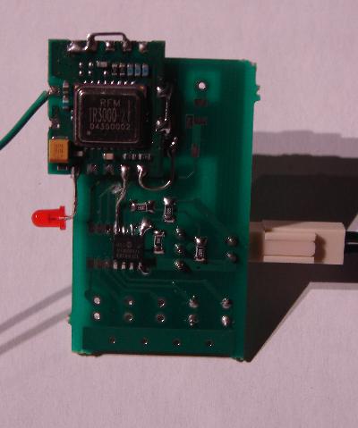
These are quite acceptable to incorporate into projects, as most of the RF is integrated onto the small pcb. I would make a spot on a final PCB, for the small RF daughter chip. become more energy aware |
||||
| davef Guru Joined: 14/05/2006 Location: New ZealandPosts: 499 |
Sorry Gordon missed your 7June posting. Was just reading a good summary on AVRfreaks, search for the thread called: RF Modules Legal? Sounds like you are able to sync on just just one nibble. I thought it might need more, from the discussions I have read, but the proof is in the results. The thread mentions Manchester encoding, but my understanding is the requirement for Manchester has more to do with the following: - the receiver detector's ability to handle "unbiassed" data, ie more zeros or ones than the idea 50% and - the length of data packets before synchronising again, ie short data packets plus another preamble before the next data means you are likely to get away without using Manchester. Sounds like you are making good progress. Dave |
||||
| GWatPE Senior Member Joined: 01/09/2006 Location: AustraliaPosts: 2127 |
here is the successful picaxe coding, for the TX, and signal quality testing receiver, pictured above. ********************************************* transmitter code just the Tx subroutine txdata: serout 0,N2400,(%0011,"bat1V",#W6) serout 0,N2400,(%0011,"bat2V",#W6) return receiver coding #picaxe08M main: if pin3=0 then main serin 3,N2400,("bat1V"),#w1 serin 3,N2400,("bat2V"),#w2 serout 0,N2400,("batV",#w1," ",#w2) if w1=w2 then green red: high 2 pause 100 low 2 goto main green: high 1 pause 100 low 1 goto main end ************************************************** This system has had the lowest error rate so far. The 2 text qualifiers, can be anything, as long as they are the same sequences in the Tx and Rx. Gordon. become more energy aware |
||||
| GWatPE Senior Member Joined: 01/09/2006 Location: AustraliaPosts: 2127 |
The telemetry is now suitable for a real application, monitoring battery voltage, and relaying a series of status indicators. I have been able to encode the digital inputs, windmill enable indicator, diversion load active, battery maintenance controller status and battery voltage, into a single picaxe word, that can easily be transmitted. The unit can now display inside, what is going on outside in the power shed. The 10bit analogue word [battery voltage], has 6bits free. I was able to encode the additional digital bits into the free bits. These digital bits can then be extracted out of the data packet, and can be decoded back to indicate the original information, so the battery voltage remains available for display as well. A 2 line LCD can be used for the output, but I will be using a picaxe14M to display the info with some LED's. I will be using 3 LED's for the battery status{green/good}, {amber/fair}, {red/low}. There will be a Rx packet status indicator{green}, a windmill enabled indicator{white} and a diversion load active indicator{red}. When the battery is full >28V, all 3 battery led's will be ON. If the battery is above 27.6V, the 3led's will Pulse and scroll, to indicate battery absorbing. I will be adding the few extra lines of code to my own windmill controller. I will be revising the code to reduce the total bytes needed for reliable transfers as well. Gordon. PS edit. something strange happened with the brackets. text went coloured as well. All seems OK now. I was able to reduce the qualifier string down to 2bytes, and the encoding/decoding allows all the info to be transferred in a single picaxe word variable{16bits}. become more energy aware |
||||
| woodchips Newbie Joined: 05/01/2009 Location: United KingdomPosts: 27 |
Hello, I can possibly shed some light on the data errors. With cheap devices that use RS232 serial communication it is almost 100% certain that the crystal or resonator they use is not an exact multiple of the baud rate. What happens is that the data is sent and the receiver happly synchronises to the start bit, and then samples at the mid-point of the bits in the byte. If the baud rate is incorrect then the bit to bit sample point drifts until it actually goes out of the bit period and hence causes errors. This can happen surprisingly quickly, in just 2 or 3 bytes sometimes, or even faster in your application. The best solution is to always program the transmitter to send 2 stop bits, the spare bit acts as a timing resynchroniser. The 2 stop bits are never used by the serial chip, one bit is always enough. An alternative solution is to wait until the byte has been sent and then add a small time period, so the bytes are never sent with no dead time between them. This can be taken to extremes, send just one byte per second, data rate isn't realy a problem. Bob |
||||
| GWatPE Senior Member Joined: 01/09/2006 Location: AustraliaPosts: 2127 |
Hi woodchips, The picaxe micro is the RS232 coding, and decoding chip. There are fixed protocols for the basic commands. I am now using the newer tranceiver units operating as receivers. There must have been a problem with the cheaper receiver unit that I first tried. The micro in each case was not changed. The important aspect seems to be the transmission of a small data packet, to lock the receiver ready for serial data. I am using positive logic, so the no data state is a low signal. Units are working really well now. I now have a portable unit that indicates windmill operating status and battery charge status. All good for an RE system. Gordon. PS I still have to investigate sending more data. become more energy aware |
||||
| davef Guru Joined: 14/05/2006 Location: New ZealandPosts: 499 |
*** With cheap devices that use RS232 serial communication it is almost 100% certain that the crystal or resonator they use is not an exact multiple of the baud rate. *** I would generally expect that someone who supplies any communications device would specify or supply a crystal that gave 0% errors at their specified baud rate. IF you want to change the crystal to something you have laying about OR use an unspecified baudrate THEN be aware that there is a "magic" relationship between crystal frequency, divider ratios and baudrate. The AVRs I work with can tolerate +/-2% offset. There are special crystal frequencies, like 3.6864MHz, that will give 0% at all common baudrates up to 230.4kbps. Does the second stop bit just put in the small delay you suggested as a solution? If not, could you explain how re-synchronisation occurs? Regards, davef |
||||
| GWatPE Senior Member Joined: 01/09/2006 Location: AustraliaPosts: 2127 |
The problems mentioned above with RS232 will cause problems with all transmissions, including those with wires, not only those experienced with a radio link. I have never experienced errors with picaxe comms with wires, only with the radio links. I have used modems since Bulletin Boards were popular. There is so much bandwidth available with modern comms, that the error correction systems that are still operating have less impact for the average user. The back to basics with these 433MHz units and low Baud, 4800bps bring back old memories. There have been so many CRC checksum protocols. Most could not be implimented in the memory and processing power of the picaxe. I have limited most transmissions to <50 bits. By programming the receiver to wait for specific data, prior to the start bit, the errors have reduced to almost nill. I suspect that the Baud matching would be better than 1% for most cheap units like a picaxe. I would expect that high end units would be ppm tollerances. Gordon. become more energy aware |
||||
| davef Guru Joined: 14/05/2006 Location: New ZealandPosts: 499 |
*** The problems mentioned above with RS232 will cause problems with all transmissions, including those with wires, not only those experienced with a radio link. I have never experienced errors with picaxe comms with wires, only with the radio links. *** Agreed However, one of the biggest sources of grief for people using microcontrollers within builtin (RC) oscillator sources is that that are generally not accurate enough for serial comms. You need a frequency determining element that will stay within a few % over the temperature range and be on the right frequency. |
||||
| Janne Senior Member Joined: 20/06/2008 Location: FinlandPosts: 121 |
One idea would be to use xbee modules instead of the 433mhz RF modules. They would include all the error checking and other stuff in them, making them very easy to use in this kind of application. And with price starting at about 19� / � piece for one ( you need at least 2, one for receiving and one for sending) they're cheap compared to the convenience they make. If at first you don't succeed, try again. My projects |
||||
| GWatPE Senior Member Joined: 01/09/2006 Location: AustraliaPosts: 2127 |
Hi Janne, I am familiar with the ZeeBee{XBee} modules. I doubt that the user interface will be easy to build, at the computer end, and the micro end measument end. The most reliable connection is direct Motherboard RS232. The Serial-USB adapters {Belkin/Prolific chipset type} introduce errors in the comms. I have noticed approx 2-5% corruption occurs. I have built some data transmission error checking into my VB logging application. My application is now stable for all adapters I have tested. I will be adding similar testing to my revised Piclog application in the future. Gordon. become more energy aware |
||||
| woodchips Newbie Joined: 05/01/2009 Location: United KingdomPosts: 27 |
Hello, back home again. The RS232 signal is active low on the chip pins, so the idle state is a logic high. The receiver continually monitors the pin looking for a low. When it sees a low it counts for 8 internal clock periods before accepting that this really is a start bit. It is 8 clock periods because the receiver is programmed so that the clock it uses is 16 times the baud rate, so each bit period has 16 clocks. Once the start bit is detected then the receiver samples another serial data bit after every 16 clocks. This, if the baud rate is exactly 1/16 of the receiver sample clock, means that each bit is sampled exactly in the centre, no errors. It knows how many data bits there are from the setup programming, and when the stop bit is received the byte is transferred to the output data bus holding register. If another stop bit is coming then it has no effect, just delays the recognition of the next start bit by one bit time. It is now obvious what goes wrong. If the baud rate is not exactly 1/16 of the receiver sample clock then the sample point will drift. This drift can be early or late. If the drift is too large then the sample point can end up in the next bit period. If bytes with one stop bit are being sent continually, no idle gaps, then the detection of the start bit can drift later and later in the start bit. It only looks for 8 consecutive lows, not 8 consecutive lows after a high, the previous byte's stop bit. Experience has proved that only expensive computer kit has the exact correct baud rate. I first came across this on an Apple 2, and since then on almost anything where the RS232 port is just used for status or minor control uses. The advantage of RS232 is that the data stream can be easily looked at, a scope or logic analyser, from where the baud rate can be checked. Does the Picaxe use the Microchip PIC processors? If so then what is the resonator/crystal/RC oscillator frequency? The older PICs I use (16C73 family) can only use an RC oscillator if the low power state is wanted, with obvious temperature and component tolerance problems. Even a resonator is only +/-0.5% initial tolerance. Do the radio modules use the PIC? The RS232 should be completely error free. Putting forward error correction like CRC in, or special software protocols looks to be papering over the real problem, might be worth hunting that down. Bob |
||||
| Page 1 of 2 |
|||||
| The Back Shed's forum code is written, and hosted, in Australia. | © JAQ Software 2026 |
