| |
  Page 2 of 2 Page 2 of 2 |
| Author |
Message |
GWatPE
Senior Member

Joined: 01/09/2006
Location: AustraliaPosts: 2127 |
| Posted: 10:48pm 21 Jun 2009 |
 Copy link to clipboard Copy link to clipboard |
 Print this post |
|
Hi Bob,
All of the error checking protocols require bi- directional traffic. The processing overheads would result in the primary role of the picaxe being for data transmission. This would likely require a separate processor for this. Hardly viable when the primary role of a single processor like the small picaxe barely handles the control loop alone.
I use positive logic for the RF data transmission to reduce power consumption and cct complexity, and component count. No Max type chips involved.
All is working remarkably well now, with data checking in the VB PC application as well. This is one way traffic.
Gordon.
PS edit: The RS232, in the original std, with double handshaking, either hardwired, software, or both should be error free. The problems occur with 2wire and RF systems, when there is no handshaking possible, hardwired, or software. The sync pulse, system, similar to that used by analogue video and TV allows reliable transfers to occur with one way traffic.Edited by GWatPE 2009-06-23
become more energy aware |
| |
GWatPE
Senior Member
Joined: 01/09/2006
Location: AustraliaPosts: 2127 |
| Posted: 01:23pm 25 Jun 2009 |
Copy link to clipboard |
Print this post |
|
I have just finished some more testing of COMMS, RS 232 style.
I have tested 3 SER-USB converters and a PCMCIA-SER adapter, against a direct wire link when used with an RF 433MHz link.
I have come to the conclusion that direct wire link is error free, only when the connection from the picaxe is direct to a PC on board COMM, 1 or 2, or to a PCMCIA-SER adapter. The USB-SER converters introduce more errors than the RF link.
I will be investigating this further.
Gordon.
become more energy aware |
| |
woodchips
Newbie

Joined: 05/01/2009
Location: United KingdomPosts: 27 |
| Posted: 06:04pm 25 Jun 2009 |
Copy link to clipboard |
Print this post |
|
Gordon
It is easy enough to have error checking and correction without bidirectional data. The checking can be simply parity or CRC, but you just know it is wrong. For more complex applications use forward error correction where a sufficient number of extra bits are sent to allow the receiver to both detect some, and correct fewer, errors. Hamming distances and such like.
The two wire and RF applications are half duplex, so only one end can send at a time. This is similar to the Ethernet protocol, carrier sense, multiple access, collision detect, CSMA/CD. Each transmitter has to monitor the data out pin, and if it reads different to that which was sent then that means the other end is also transmitting. Both ends will detect this, they back off and then retry. You would be amazed how many networks use the same back off time at every node so they retry again, and again, and again... Because there is a finite data transfer time then just checking that the network is idle and then transmitting isn't enough, the other end can start as well. It is only when the data gets corrupted that both ends realise something has happened. That the corruption can occur in just a small part of a bit period adds to the problem, can't assume that the bits are synchronised from each end.
This all takes time and code of course, to the point where forward error correction, if done by lookup tables rather than calculation, is possibly the more efficient solution.
Another solution is for the receiver to always request the data. The transmitter never sends anything unless asked, and because the sent data packet is a known, consistent, size, it can always receive it without contention. The transmitter just needs a timeout so it never tries to send after its allocated slot has ended.
Not simple I know, but understanding the problem is the only way forward.
Bob |
| |
GWatPE
Senior Member
Joined: 01/09/2006
Location: AustraliaPosts: 2127 |
| Posted: 12:55pm 26 Jun 2009 |
Copy link to clipboard |
Print this post |
|
Hi Bob,
I have reworked the comms again and have now restored reliability back again. I had used a data layout similar to that for the piclog, with data identifiers embedded in the data stream. This produced many errors.
I now have a system that allows me to log directly from the transmitting picaxe using either a wire link, or wireless RF units. The solution I now use with most success is: The transmitter sends 3 packets of data in each burst. Packet one contains 7bytes of data for the direct wire link transfer. This contains a start character byte, a data word, a seperating character byte, the data word again and then a final byte character. The required data is compressed into the single 16bit word. The second and third data packets are used by the RF link. The second packet contains the nibble that sync's the reciever, and a 2byte sequence identifier followed by the 16bit word containing the compressed data. The third packet is the same as the second, with only a different 2byte sequence identifier.
The RF reciever ignores the first packet and locks onto the second and third packets. The reciever then checks that the data is identical in the packets and then retransmitts the data in the same direct wire link format. The reciever also decodes the data and indicates all status on an LED array.
The computer logging program has to decode the data packet on the normal serial wire connection, from either the RF reciever retransmit output or from the original wire link RF transmitter output.
The simplified system uses a uniform 2400 baud rate, rather than a mixed 2400/4800. I use the serout command for all transfers, rather than the sertxd. I have limited the overall data rate to around 2 updates per second. This gives plenty of signal averaging for the logging at 0.1Hz.
The data file size approximates to 200k/day.
The transmission of a duplicate compressed data set has overcome the problems I was having with the SER-USB converters as well. The 50 or more characters I had previously tried to decode has now reduced to 13 in one packet, and 7 in each of the other packets. These are handled independently, so are not additive. Each micro system has a low overhead with number crunching and the computer logger handles the decoding within a 100 or so mS. The computer logger could now easily be replaced with a micro solution as the date/time stamp takes up half the required memory. May be worth looking at the EEPROM after all.
Gordon.
PS edit:
The logger is working while I continue to compose this posting, with no apparent data loss. HeHe. Battery is down to 25.1V, so time to close up shop.
Edited by GWatPE 2009-06-27
become more energy aware |
| |
GWatPE
Senior Member
Joined: 01/09/2006
Location: AustraliaPosts: 2127 |
| Posted: 02:15pm 30 Jun 2009 |
Copy link to clipboard |
Print this post |
|
I have just finished the RF link logger for my windmill. The finished unit was able to be added inside the shell of a Belkin SER-USB converter interface. The RF receiver and the picaxe decoder fitted with a little room to spare. The DB9 has the link plug, so the unit still functions normally as well.
The VB front end incorporates the additional error checking needed with the USB adapter. The picaxe handles error checking for the RF link.
The Belkin unit has LED indicators.
Thanks to Gizmo for providing COMM software interface tools and graph display window. I have heavily modified much of the piclog source, to reflect the different purpose I have to the original piclog. Not too much of the original source left unfortunately. I was not able to get the listbox to update at a fast enough rate, so I had to change to individual textbox displays. All is working well and the site test went without any problems.
Here is a pic of the unit.
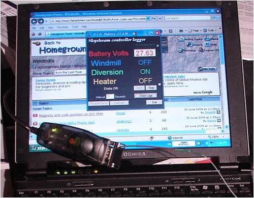
The Belkin interface is resting on the keyboard, and the display window shows the battery voltage and the status of the windmill controller.
Gordon.
become more energy aware |
| |
| |
Page 2 of 2 |
