
|
|
Forum Index : Electronics : Another Active Cell Balancer, BMS
| Author | Message | ||||
| Solar Mike Guru Joined: 08/02/2015 Location: New ZealandPosts: 1228 |
I have been toying with the idea of another active cell balancer design, using a forward converter for each battery cell and a mechanism to read the individual cell voltages by transformer action. If all coils are wound on the same 65mm ferrite core and drive signals are synchronous, then any cell with a higher voltage than the others will pump current into lower voltage cells, by simple transformer action of voltage difference, at the inverter switching frequency, 60Khz in this case. In order to perform core reset, the pwm on period must be 50% or less. To measure the individual cell voltages, we have a voltage reference winding and a precision full wave active rectifier. If individual cell converters are switched on, then the voltage at the reference winding is representitive of that cell and as this is a common volt meter, easilly calibrated; thats the theory anyway. Here is a partial schematic for each cell, it uses an inexpensive mosfet isolated driver (Pai8211A) and 12-12v 1w isolated psu from LCSC. A shift register is used to turn off\on the cell inverters as required; they can be easilly linked to control another bank of 8 cells. As each cell electronics is duplicated, I might approach this by placing those components on small pcbs, then soldered or plugged into a common carrier board that has the battery cell connections and a cpu controller of some sort. Here is the base schematic: 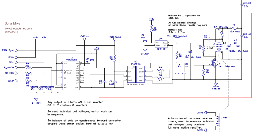 Cheers Mike |
||||
| Solar Mike Guru Joined: 08/02/2015 Location: New ZealandPosts: 1228 |
Right some progress, I have come up with a 50x50mm pcb to host the switching components for one cell, as per the schematic in the red box above. Using a 30 pin pcb edge card connector to allow plugging cards in\out for testing. The mosfet switch HSBA4088A (40V 255A 0.85mΩ@10V,20A 110W PRPAK-8(5x6) ), should remain cold for balance currents up to 20 amps, I doubt it will achieve 20A, as current is determind by voltage difference and impedance or resistance of the circuit including the balance wires, transformer windings and fuse etc to each cell. Here is the pcb 100x100mm with 4 cards: 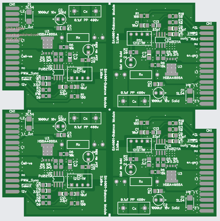 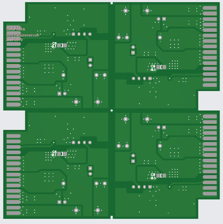 Will work on the mother board next. Cheers Mike |
||||
| Solar Mike Guru Joined: 08/02/2015 Location: New ZealandPosts: 1228 |
More progress, have laid out the start of a 16 cell mother board, each set of 8 cell modules are driven by a 74HC595 serial to parallel shift register. The large ferrite core sits in the middle of the pcb, using 5mm wide pcb tracks top and bottom to connect to the cell balancing plugs. The common 60 Khz PWM sync signal to all modules is buffered by a dual 74LVC2G17 logic gate. 12 volt power to cell modules can be switched on\off for power saving. The 60 Khz cell reference winding for measuring individual cell voltages goes to an active full wave rectifier, then an averaging filter, I'm using a 10Mhz OPamp here TLV9064. Just have to add a cpu and a few other IO bits. 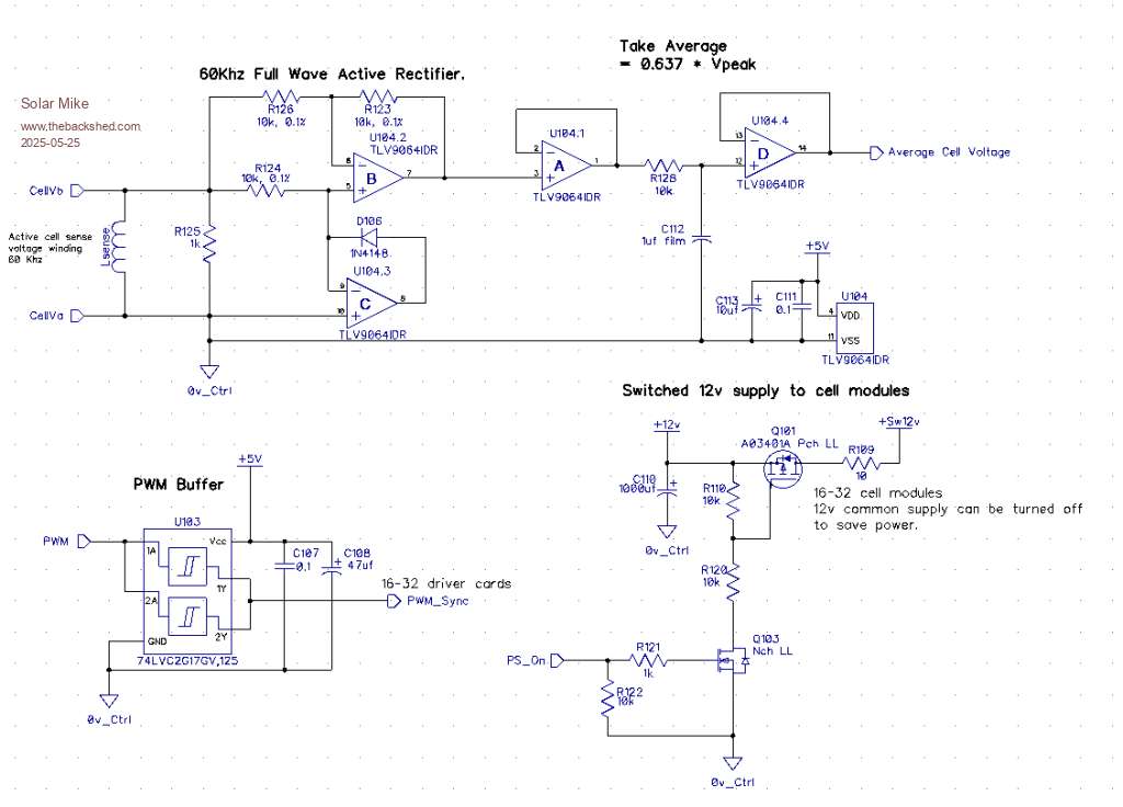 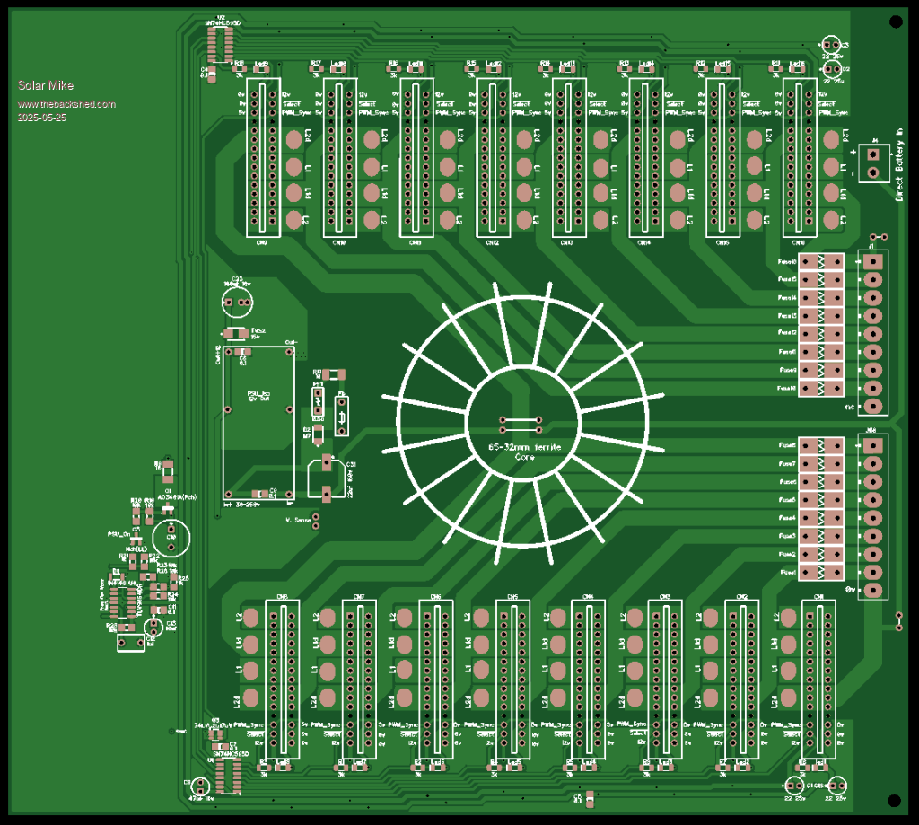 Cheers Mike |
||||
| Solar Mike Guru Joined: 08/02/2015 Location: New ZealandPosts: 1228 |
PCB completed, hope it works otherwise I have wasted 35hrs; I managed to find some white papers on theoretical design of forward converter balancers, they don't really give any specific details other than pages of maths, so it should work.... in theory. I haven't drawn up any more of the schematic other than already posted, may do so if it works ok. Have made the mother board extendable, so a second board can be connected, minus power supply\CPU, to allow another 16 cell modules for a 100 volt Lifepo4 setup. If I wind a number of turns on each core and join the two cores together, then that should allow balancing across all cells, due to the synchronous switching. PCB has 3 relays for High Volts, Low Volts, Load On, an output for "Balancing" and a serial output to an LCD display or a string of status leds. CPU is the 20 pin Picaxe. Checked it several times, cannot see any errors, so will send it off to be made, pcb size is 240 x 227mm, a little costly to get 5, if it doesnt work. Edit Note: I did purchase an 8s inductive balancer off AliExpress a while ago, just to see what was in it, it has a 30mm ferrite toroidal core with 8 sets of windings and at a guess would work in a similar fashion. I tried it out on a couple of mismatched cells and it worked, but the currents were quite low. However the wire they used on the core and the pcb traces connecting to it were really quite thin, so the resistances would be too high to get the 6amps current they were advertising. The wires on the core were crossing over everywhere, so just asking for future problems with shorted turns etc, another reason to build your own. Cheers Mike .png) 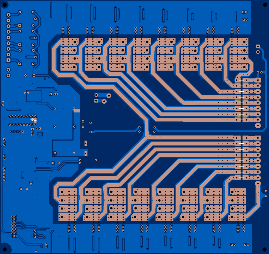 Edited 2025-05-28 21:55 by Solar Mike |
||||
| Solar Mike Guru Joined: 08/02/2015 Location: New ZealandPosts: 1228 |
Before sending the gerbers off, have made some last minute changes. The PIC CPU PWM output can drastically alter its frequency and duty cycle as the chip powers down. If the 5v rail stops or is disconnected and the system was balancing, then the changes in pwm frequency usually downwards may blow things up. I have noticed this before with various PV controller designs, usually a short grunt squeak comming from the buck inductor, never really did any harm as the power to the circuit was removed. However with 16-32 inductors effectively shorted across each battery cell, there may be a lot of smoke. To prevent this, have added a MAX810LTRG 5v rail monitor and some logic to shut down the PWM sync drive should the 5v rail ever drop below 4.63 volts. Amended part of the schematic below: 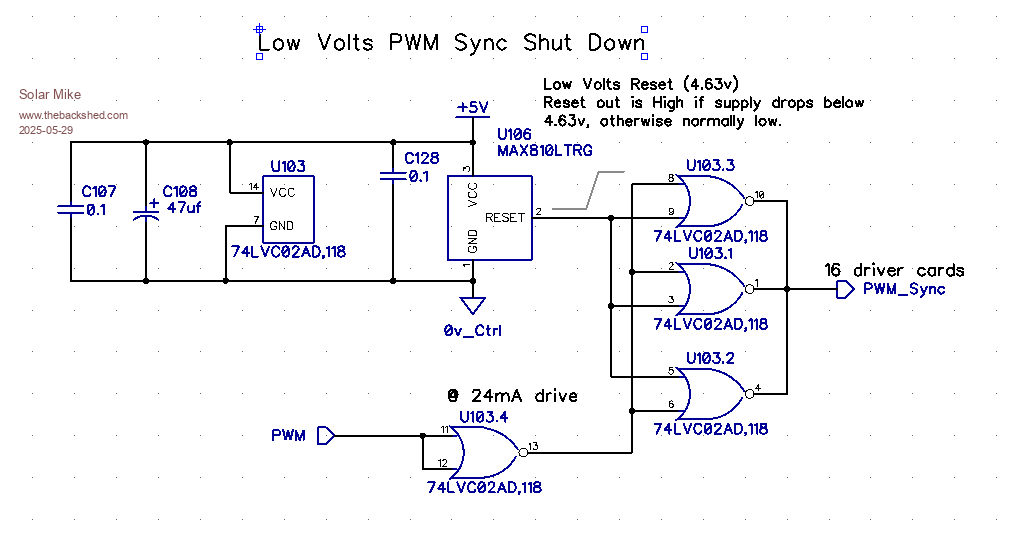 Cheers Mike |
||||
| Godoh Guru Joined: 26/09/2020 Location: AustraliaPosts: 675 |
HI Mike you sure put a lot of work into these designs. I guess that there must be some pretty good reasons for using Lithium batteries. I still wonder if all the complexity in managing them is worth the trouble. I know that our car has vast amounts of electronics in it to keep it all working. Just the 44 kw battery bank that powers the car must have heaps of stuff to keep it happy. But having seen plenty of electronics blow up and die due to age and heat I wonder just how long my car will last. Are they made to just get past warranty period or are they likely to go for a lot longer. I am hoping the latter. Do you use lithium batteries as your home batteries? If so what advantages do you see in them. For me well I still stick to VRLA batteries for home and am hoping to get another 10 years or more from the ones I have. Maybe then I will switch. Good luck with this project Pete |
||||
| Solar Mike Guru Joined: 08/02/2015 Location: New ZealandPosts: 1228 |
One good reason for going to all the trouble here is I'm using a lot of 3.3V cells that have been rescued from failed 48v battery packs; often one or two cells will go bad, or the battery BMS reports them as having failed in some way. After pulling a few of these sealed batteries apart, its more the case that the failures are the cell terminal connections, especially the ones with laser spot welded bus bars. The welds go faulty after some time as the cells are not securely clamped together, they are mostly stuck together with multiple wraps of fibreglass tape, this allows the cells to flex placing stress on the non-flexible welded terminals and so they fail with a high resistance connection, might be ok with small loads, but when attempting to draw off 100 amps or so they fall over. Because everything is welded together, the battery is a write off, a single cell cannot be replaced, the whole battery has to be wrecked almost beyond repair just to get into it. Some fail due to the crappy BMS quality - construction and wiring, mainly by the bms unit blowing up catching on fire. One could say, these cheaper sealed Lifepo4 batteries are designed to fail, at some point, personally I wouldnt go near them, just trouble waiting to happen. This means the cells I'm using are not evenly matched, and a balancer with a high current is required; Its easier to make my own in this instance. For new well balanced and matching cells, not much complexity is required, most high quality off the shelf BMS systems will be fine. We have an EV also, MG ZS, I would expect with modern EV's the battery will last 400,000 kms plus without any problems, if it has LifePo4 cells, cannot say for NMC chemistry as life more depends on how the battery has been treated. After having used Lifepo4 cells here at home and on various other installations, I would not go back to lead, Lifepo4 are so much more efficient, they charge faster and can output much higher current loads than a similar sized lead battery. Cheers Mike |
||||
| Godoh Guru Joined: 26/09/2020 Location: AustraliaPosts: 675 |
Thanks for the explanation Mike, it sounds like you have a cheap supply of battery parts so that is a good way to go. Pity that the batteries are designed to fail in the first place. I have seen some very cheap LiFePO 4 batteries but shied away from them as their capacity was lower than the rating. I have tried to find information on the MG ZS EV battery (ours is gen 1) but all I have seen says that they are Lithium. Our car only has about 25thousand Kilometres on it so if we get 400 thousand then the batteries will probably outlast the rest of the car. Good luck with the cell balancer and the batteries Pete |
||||
| KeepIS Guru Joined: 13/10/2014 Location: AustraliaPosts: 2196 |
Hi Mike, IMHO this is a really great design and board layout. Obviously that higher current is not normally needed, but it's nice to have the capability if needed and it certainly makes it robust in normal cell use. I have also also looked at the AliExpress devices in the past and was also unimpressed. I wonder how accurate the Cell voltage actuality is. If F1 on a balance board fails for what ever reason, I wonder what the cell voltage output would indicate. I'm thinking here of an alarm enable and the possibility of expanding the balancer to completely control a pack, everything is basically there to do that if cell voltage is accurate to within a few mv, obviously some code changes but that's easy. Wonder what your thoughts are? NANO:Inverter V 8.2ks - Linux AvrDude GUI script V4.1 |
||||
| Solar Mike Guru Joined: 08/02/2015 Location: New ZealandPosts: 1228 |
@KeepIS, PCB's are being made now, so until I have them and made one up to test, cannot comment on how well the cpu can read an individual cells voltage, the leakage inductance between the measuring reference coil and other individual cell coils may vary sufficiently as to give inconsistant readings. As for fuses, using smd reset poly fuses on the cell balance wires, so in theory they wont blow, however if one did, then that cell would have no switching output into the common transformer core and thus no reading on the common reference coil. It will be an interesting experiment. Cheers Mike |
||||
| KeepIS Guru Joined: 13/10/2014 Location: AustraliaPosts: 2196 |
Looking forward to seeing how this goes, it's not hard to get cell voltages for the individual cells in any case and I'm not worried about a fuse for final cell protection fail-safe. This part of the OFF-Grid system is the last thing that is commercial, so having something we can built and have spares and circuits for is where I'm heading with something like this. I have four 16 cell LiFePO4 batteries and the only thing I use each BMS for is individual cell OV and UV protection, OC is external and includes Fuse fail safe per bank. I use 2A balancers which work reasonably well, 5A to 10A would be better for quick top balance occasions, so a good balancer with a few mods would be ideal. Will follow with great interest, it's an interesting experiment indeed  NANO:Inverter V 8.2ks - Linux AvrDude GUI script V4.1 |
||||
| The Back Shed's forum code is written, and hosted, in Australia. | © JAQ Software 2026 |
