
|
|
Forum Index : Electronics : Adjustable DC to DC stepdown converter with on/off i/p
| Author | Message | ||||
Dinosaur Guru Joined: 12/08/2011 Location: AustraliaPosts: 357 |
Hi All Looking for a converter around 3A to 5A output at 3.55V , that will allow a pull Hi/Lo to enable the converter output. No amount of searching seems to bring one to light. I know some of you may have modified a standard unit, but without knowing if that that is possible on some of them, I would be guessing. Anyone have any ideas ? Regards Regards Hervey Bay Qld. |
||||
| mab1 Senior Member Joined: 10/02/2015 Location: United KingdomPosts: 282 |
ali dcdc converter with enable swt These have an on/off swt which I think operates an enable pin on the chip (lm25116), but doesn't have an external enable input per se. Edited 2025-06-03 19:04 by mab1 |
||||
| wiseguy Guru Joined: 21/06/2018 Location: AustraliaPosts: 1296 |
Here are a few devices starting at 3A output all at digikey. Might be worth also looking at element14 and Mouser. You also did not state what your input voltage was so maybe some are not suitable. The following are mostly in stock and with remote on off, there are quite a few more but also becoming more expensive - the listed are in the range of $5 to $15. They are all adjustable types so 2 resistors for setting output voltage, I ran out of time to find more.... 1) 3A 2) 3A 3) 3A 4) 3A 5) 5A 6) 5A If at first you dont succeed, I suggest you avoid sky diving.... Cheers Mike |
||||
| Dinosaur Guru Joined: 12/08/2011 Location: AustraliaPosts: 357 |
Hi All Many thanks for the replies. I have had to rethink my approach. Basically I am using up good Lipo4 cells from different suppliers into one 12v battery. The problem is that they charge & discharge differently and thus cause a large cell difference if I don't do anything about it. (200-300mV) Using conventional balancers are just to slow, as they rarely put out the specified amps. Thinking outside the box, the following is the approach. Use 4 of these DC-DC converters. Amazon Isolated DC-DC Adjust each one to 3.55v and connect the outputs one to each cell. Once the voltage reaches 3.55v the charging on that cell will stop, whilst any low cells will continue to charge. This eliminates the need for an Enable I/P. My solar cells are limited to about 25A, but this output will drop once one or more cells are up to voltage. Then switching off a 100A SSR will disconnect the charging / balancing voltage and the battery will sit idle. Edit: The only trouble is that these converters have such Low output current. I can't use non-isolated as the ability to charge one cell only is upset by the common Negative. Regards The whole system is currently controlled by a Rpi Zero with cell Voltage sensing, which will also cut off the SSR when the rules apply. It also meant that I have the option of connecting the solar output directly to the Battery through a SSR until such time as the Cell delta get's out of hand. Then simply swap to using the DC-DC's. Would be interested in hearing opinions on this. Regards Edited 2025-06-04 08:58 by Dinosaur Regards Hervey Bay Qld. |
||||
Revlac Guru Joined: 31/12/2016 Location: AustraliaPosts: 1277 |
Ok I see what you are trying to do, do you really need that much current? that would be great for getting them up to equal voltage fast, but after several cycles I think you would not need that much.....If you where still going to do the rest of the charging through and ordinary common port BMS. Or are you just going to charge the entire battery using these converters? the BMS would still be necessary for over-under voltage protection. Cheers Aaron Off The Grid |
||||
| phil99 Guru Joined: 11/02/2018 Location: AustraliaPosts: 3293 |
One thing to check with any DC-DC module is the reverse current with no input. If the only drain is the output voltage divider that is probably too small to matter. If the rest of the circuit is still running it may be more significant. It may be possible to use non-isolated buck converters by putting the cells in order so that the cell that charges fastest (the one that never needs extra current) at the positive end down to the one that needs the most current at the negative end. Unless these converters are part of a MMPT system the cell at the positive end wont need any extra current so wont need a converter. For the middle two cells the negative of each converter ONLY goes to the negative of it's cell. Do not connect it to the solar negative, the return current will flow through the lower cells. For the cell at the negative end the converter negative will also connect to solar negative. |
||||
| Dinosaur Guru Joined: 12/08/2011 Location: AustraliaPosts: 357 |
Hi All Aaron, I can have the best of both worlds, use both single cell charging and Total battery charging, just not together at the same time. Phil Now that I have to think about. One plan I had was to use non-isolated adjustable so that each cell gets Voltage based on it's position. ie: 14.4 then 10.8 , 7.2 and finally 3.6. However, assume cell 3 is low and by supplying 7.2V to it, my concern is that cell 4 will get a current flow as well and may go over the limit. Another plan I saw googling was to put the 4 dc to dc's in series. ie: Daisy chaining the supplies only. (Negative from converter 1 becomes Positive for converter 2 etc) Then the output of each converter to each cell. But I have no idea as to the current flows in this scenario. Regards Hervey Bay Qld. |
||||
| Solar Mike Guru Joined: 08/02/2015 Location: New ZealandPosts: 1214 |
With a low frequency bang bang pwm PV charge control system , eg SSR control of PV array direct to the battery, the battery is subject to large PWM current pulses; this makes it very difficult for any cell balancing system to stop individual cells voltages from going excessively high. Having disparite cells in the battery makes this situation even worse as you have discovered. If you use a charge controller that effectively limits its voltage output and so has a tapering current charge profile at your end point voltage; even with disparite cells, the situation will be vastly improved and those lower current active cell balancers may work ok. I have built a few setups where the cells are all over the place capacity wise and have had to design my own high current balancer, especially when using a low frequency PWM charger. If a higher frequency PWM charger is used (several kHz) switching frequency or an MPPT charger, then the cell voltages don't peak as much and its easier to manage them. Cheers Mike |
||||
| Dinosaur Guru Joined: 12/08/2011 Location: AustraliaPosts: 357 |
Hi All Mike, my system is not PWM, it is simple On/Off control using SSR. The solar cells limit the actual charge current. (25A into 280AH) However, when I get closer to 95%, I change to low frequency pulse charging (15 sec On, 15 sec off) This has worked well for the last 10 years. I think the main problem causing cell imbalance is the Inverter drawing 95A when running the Microwave.But that is only since I have rescued mismatched cells. The Heltech balancers take upto 8 hours to balance 2 or 3% of battery capacity. That is why I am so interested in individual cell charging / balancing but with at least 3 Amps. That also allows nice tapering off when the cell nears the converter voltage. (ie:3.55v) Regards Hervey Bay Qld. |
||||
| Dinosaur Guru Joined: 12/08/2011 Location: AustraliaPosts: 357 |
Hi All This may be the solution. MJW15-12S033 Using the 3.3v output version and applying a 6% trim resistor, it will allow adjustment to 3.55v, is fully isolated and can deliver 3.5A. Worth experimenting with once I find out where to get one. Regards Hervey Bay Qld. |
||||
| Dinosaur Guru Joined: 12/08/2011 Location: AustraliaPosts: 357 |
Hi All Just a progress report. Ended up buying DDR-15L-3.3 (spec's attached) So, simply connecting my battary into 3p(2p) x 4s I ended up with 12v 300+ A/H of two different cell types. I have 100AH cells and 200AH cells, so some are 2p whilst others are 3p x 100ah. When charging the battery as a whole some cells are going to reach 3.5+ v before others. That's when I stop the Battery charging and switch to Cell charging. The DDR-15's are adjusted to 3.6v and will put out 4.5A or more depending on how far down the cell is. If the cell is to far down the current limit is exceeded and the DDR-15 goes into "hiccup" mode. (their terminology) The current tapers off when the cell gets closer to 3.6v. The end result is that the DDR-15 will pump out 4.5A from about 3.25v resulting in the cell voltage climbing about 3mV every 15 sec's.(If no load on battery) The overall performance is a bit hard to read, as when I tested it,the cells at the 12v end were higher by about 200mV to start with. This results in some settling to the next lot of cells. Either way once they got to 3.61 approx, current dropped to zero and as you can see from the enclosed picture the delta was 16mV. (ignore the 99%) This is mainly due to NOT being unable to set the voltage accurately with the trim pot. At the moment I am awaiting delivery of an accurate voltage reference and a current detector with logic output. If during the day the solar voltage drops below being able to charge the whole battery (or gets less than say 100Watt), the logic output will tell me and I will turn off Battery charging and revert to Cell charging. I am using a 9v to 24v step up converter (10A) to power the DDR-15's. Typically at the start it draws about 70Watt.(ignoring converter efficiency) So if in cloudy conditions the solar panels can deliver 70 watt or less, I will get current to charge the cells which I wouldn't if I tried to charge the whole battery. I have turned my bench power supply down to 12v and lower whilst still getting 4.5A into a cell. The current drawn by the power supply verified that. Have not yet been game to test Battery Charging & Cell charging together. The only issue is feedback voltage from cell to DDR-15, but it only draws 45micro amps per unit. Tried blocking diodes (MBR-735 schottky) but current stopped flowing when voltage difference got less. So, not sure what is going on there. Then tried using p-channel mosfet TRF9540N as a blocking diode. But it wouldn't even switch ON. So, I guess 180 micro amps running 24/7 is not going to kill me. Regards 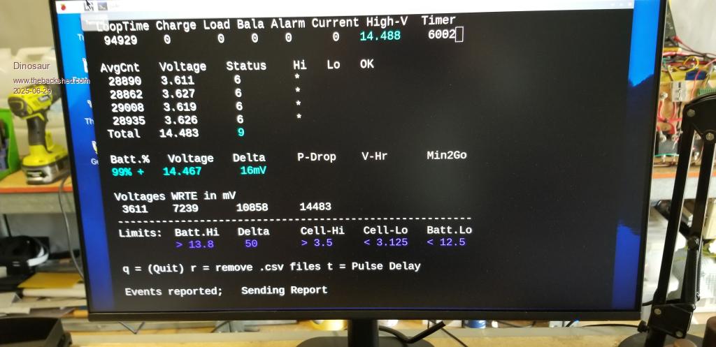 DDR-15-spec.pdf Edited 2025-06-29 15:10 by Dinosaur Regards Hervey Bay Qld. |
||||
| The Back Shed's forum code is written, and hosted, in Australia. | © JAQ Software 2026 |
