
|
|
Forum Index : Electronics : Sinewave Notch During AC Coupling – Choke Saturation?
| Author | Message | ||||
| jony787 Newbie Joined: 07/01/2025 Location: Puerto RicoPosts: 7 |
Hi to all, I’m working on a low-frequency inverter using a variation of unipolar SPWM. It uses a modified unipolar scheme similar to the EG8010: in the first half of the sinewave, one leg holds the negative-side MOSFETs ON while the other pulses with a complementary SPWM signal. In the second half, the roles swap — the opposite leg holds the negative rail while the first leg pulses. Only one leg switches at the carrier frequency per half-cycle, which helps distribute switching heat between both sides of the H-bridge. During AC-coupled charging, I also throttle the output frequency to control charging power. Frequency ranges from 60.00 Hz to 62.10 Hz, depending on system power levels. Carrier frequency change (19.9kHz to 20.7Khz during AC coupling throttle) is used to change fundamental frequency. I'm using two output chokes, each made from three PJ ferrite cores stacked together, with 3 turns per winding, resulting in approximately 235 µH per choke. Deadtime is set to 2 µs. The inverter outputs a clean sinewave under normal load, but I’m seeing a distinct notch in the waveform during AC-coupled operation (Enphase IQ7+ microinverters charging the battery through the inverter’s AC output). Here’s what I’ve confirmed: The notch consistently appears at ~¼ of the half-cycle (around the π/4 point). Output RMS voltage is around 254 VAC during AC coupling. As solar power increases, I set the code to lower the SPWM modulation to maintain stable AC voltage. At ~5500 W of charging, modulation drops to around 53%. The notching only occurs during AC-coupled charging and disappears as solar power decreases. Immediately after the notch, I see a burst of PWM pulses — more switching activity than usual. I suspect the output chokes may be saturating when current peaks from the backfed microinverters. My deduction comes from the visible ripple, increased pulse activity after the notch, and the rise in transformer temperature (154 °F) and MOSFET temperature (120 °F). Under normal load, temps are around 130 °F (transformer) and 105 °F (MOSFETs). Has anyone seen similar notching behavior during AC coupling or strong backfeed? Could choke saturation be responsible for the extra switching after the notch? Any advice on how to confirm saturation? Appreciate any insight or shared experience.  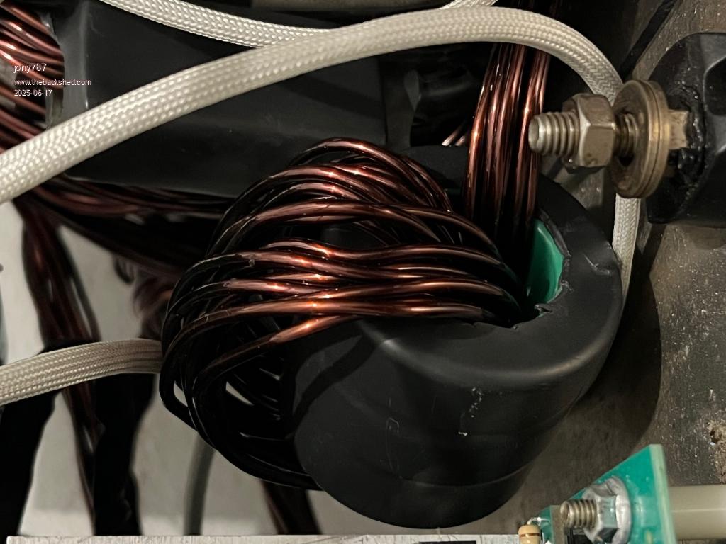 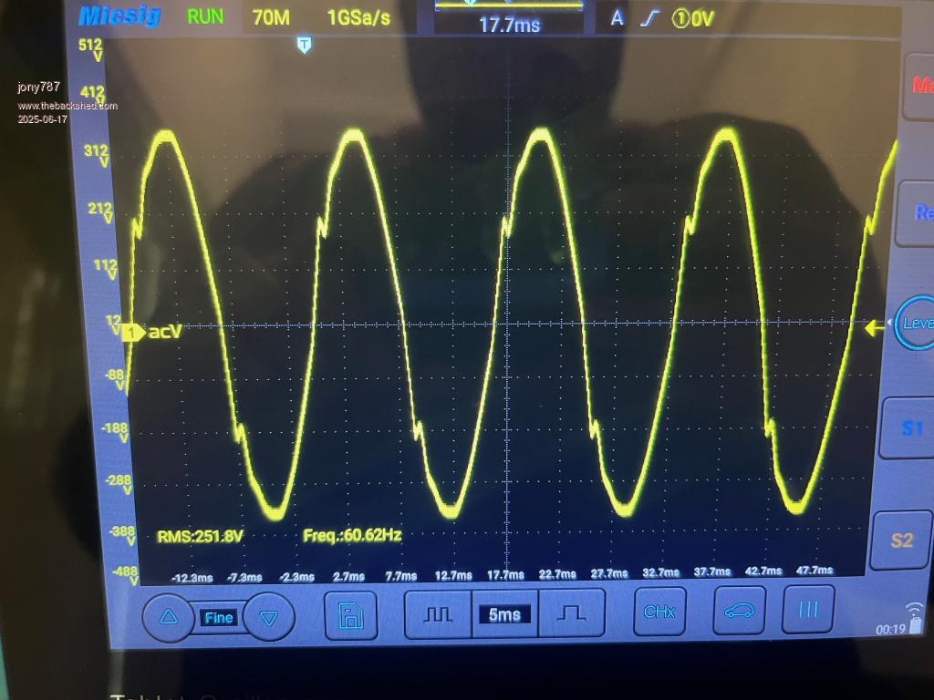 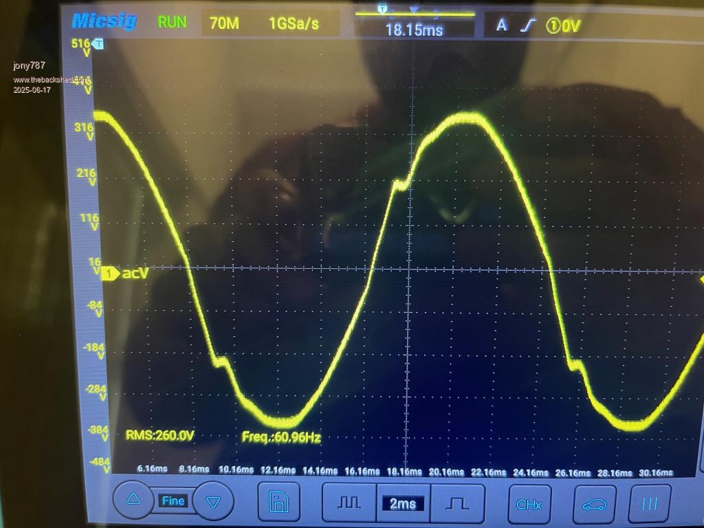 Thanks in advance for the help! Edited 2025-06-17 15:13 by jony787 |
||||
| analog8484 Senior Member Joined: 11/11/2021 Location: United StatesPosts: 204 |
What's the grid profile you are using on the iQ7's? If it's a default grid profile (for on-grid setup) then the voltage waveform distortion is most likely due to anti-islanding disturbance injections from the iQ7's. Enphase anit-islanding disturbance injections are very aggressive especially with some older firmware versions. To avoid problems you should set the grid profile to an off-grid one or one that disables anti-islanding all together. Also, you should upgrade the firmware to the latest version if it's not already done. |
||||
| jony787 Newbie Joined: 07/01/2025 Location: Puerto RicoPosts: 7 |
Thanks for your reply analog8484 Im using a dedicated Off Grid profile " Off-Grid FW60" My microinverters are on firmware 520-00082-r01-v04.40.01. I will assume since this is a Off Grid profile, its not affected by the anti-islanding disturbance injections. |
||||
| analog8484 Senior Member Joined: 11/11/2021 Location: United StatesPosts: 204 |
Off-grid profiles still have active anti-islanding just more tolerance for frequency, voltage and rate of impedance changes. Since you are already using an off-grid profile I suggest you find one with anti-islanding disabled completely. IIRC, such profiles have "AI" in the name somewhere. Your chokes appear to be using common green ferrite cores so it's likely they are saturated at 5500W (> 100A to battery). You'll need to use sendust or similar cores to avoid saturation (see KeepIS threads for more detail). Having said that, I doubt core saturation is the main reason for the distortions you are seeing. It would help determine the main distortion cause if you could capture the current waveform from the iQ7's. Anti-islanding disturbances are pretty obvious in the current waveform. |
||||
| jony787 Newbie Joined: 07/01/2025 Location: Puerto RicoPosts: 7 |
I need to get a current probe for my oscilloscope.... I made some research regarding the anti-islanding and found the following. 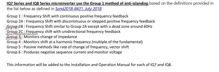 I could be wrong but it doesn't seem like the IQ7+ are pushing any distortion. I will contact Enphase since I'm still intrigued by this but most likely, IQ7+ are on Group 1. Edited 2025-06-19 09:53 by jony787 |
||||
| phil99 Guru Joined: 11/02/2018 Location: AustraliaPosts: 3317 |
"Group 3: Monitors change of impedance." It depends on how they do that. One possible method would be with a significant current pulse and measure the resulting delta V. Impedance = delta V / delta I. That could produce the regular notch you see. If your scope has 2 channels put a shunt in the line and connect a probe to each side and switch on a large load. Align the traces and read the difference between them before, during and after the notch. If there is a current pulse the middle one will be noticeably different to the others. The shunt resistance will need to be large enough to show the difference on that voltage range. Eg 1Ω would make a 10A pulse produce a difference of 10V and clearly visible. If the pulse is only 1A a higher value will be needed. For a single channel scope I guess careful measurements of those 3 points taken on both sides of the shunt then subtract the pairs of measurements. May not be as accurate but might still work. Edited 2025-06-19 10:23 by phil99 |
||||
| analog8484 Senior Member Joined: 11/11/2021 Location: United StatesPosts: 204 |
Frequency shifting is a key active disturbance injection method that can certainly cause distortions. The categories are general so while it's correct that Enphase anti-islanding mechanisms are broadly categorized under Group 1 it leaves much unspecified. For example, Enphase still monitors impedance change but it's not categorized as Group 3 because it monitors impedance change after it has injected active disturbances where Group 3 is meant for pure passive monitoring of impedance changes without active disturbance injection. It's not easy to imagine (at least for me) how active disturbances affect the voltage waveform because there are so many variables including the disturbance frequency, phase (active vs reactive power transfer) relative to the island grid voltage waveform, non-linearity (while maintaining compliance with overall THD requirements), magnitude and duration. It's also hard to describe in words only but I'll try to give an example. My experience with iQ7's with some older firmware versions (ones that had the most aggressive disturbance injections) is that they adjust the variables so to inject disturbances with large magnitude at the most vulnerable portion of the island grid voltage waveform near the zero-crossings where the grid forming inverter is barely driving the output. So, I have seen large disturbance positive current injections when the voltage waveform is barely in the negative phase shortly after zero crossing. The large injection can cause the voltage waveform to suddenly rise to above the zero crossing and become positive which effectively changes the voltage waveform frequency and/or change the island grid impedance significantly. If such resulting frequency and/or impedance change is observed by the iQ7's then they will treat it as potential islanding condition and further increase the frequency shift (i.e. positive feedback) and drive even larger disturbances until the island grid frequency is too far out of the acceptable range and the iQ7's stop producing power. If no such resulting frequency or impedance change is observed then the iQ7's will stop disturbance injection and wait until the next interval to do it all over again. AFAIK, Enphase is only major residential grid-tie inverter maker that used such aggressive anti-islanding disturbances. In newer iQ7 firmware versions (after many complaints from customers and partners doing off-grid AC coupling) it appears Enphase is now using less aggressive disturbance injections. The distortions in your scope capture appear consistent with disturbance injections far away from the zero crossings with relatively small magnitude. However, it's only a theory at this point that can best be proven/disproven with scope capture of the iQ7 current waveform and the island grid voltage waveform. This work is only necessary if you care about the details. If you just want to get past the problem then you should just use a grid profile with anti-islanding disabled completely for testing as I suggested before. After all, you system is designed to be off-grid (i.e. intentional islanding) so any anti-islanding disturbance is inherently counter productive. BTW, in case you are wondering, disabling anti-islanding does not disable the passive frequency and voltage monitoring based protection mechanisms in grid-tied inverters including the iQ7's. Edited 2025-06-20 03:39 by analog8484 |
||||
| jony787 Newbie Joined: 07/01/2025 Location: Puerto RicoPosts: 7 |
I have a ticket opened with Enphase and they are looking into the matter. I found some Kool Mµ MAX (sendust) from Magnetics and a very good price on ebay PN:0079736A7. I stacked 4 cores with 9 turns for 39uH. Sinewave looked ok so will be texting the next following days. kool mu max0079736A7.pdf Here is the new setup 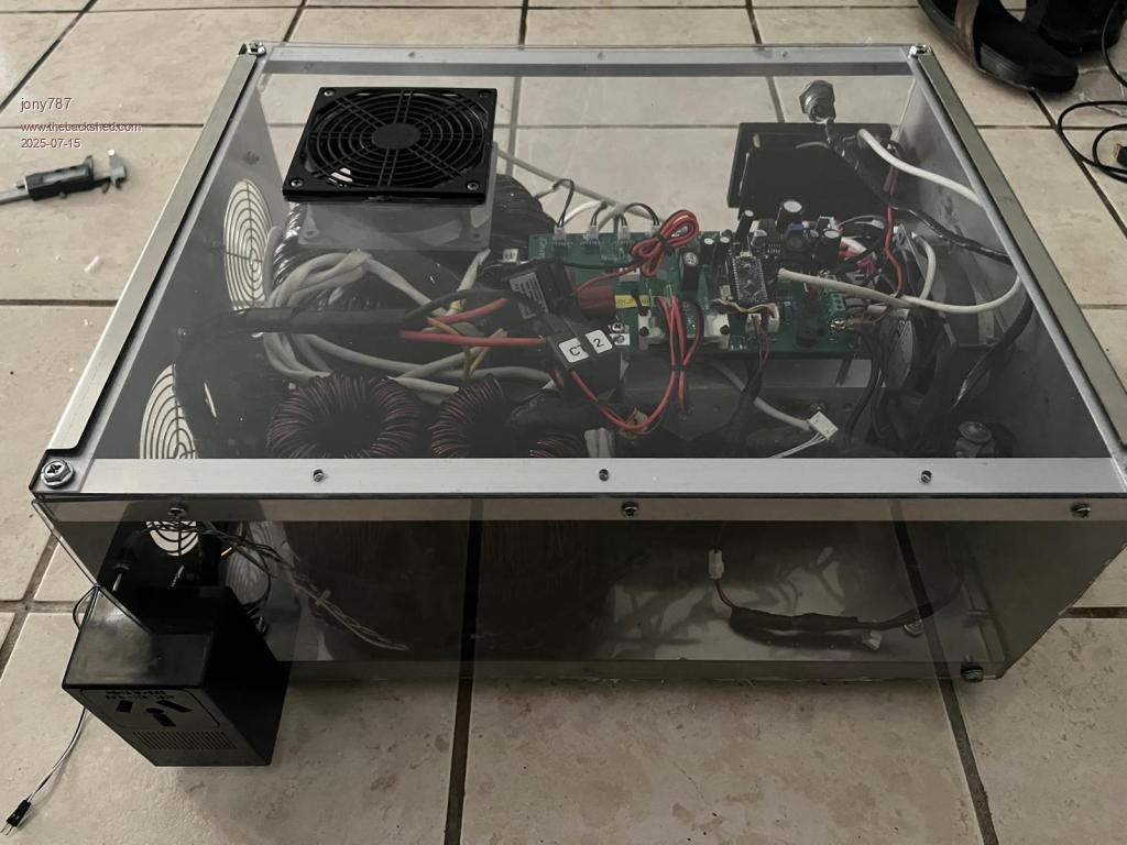 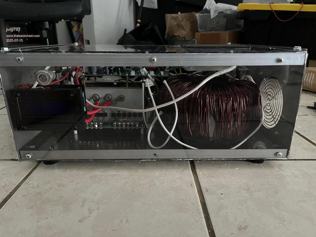 analog8484 Thanks for pointing me in the right direction. |
||||
| analog8484 Senior Member Joined: 11/11/2021 Location: United StatesPosts: 204 |
Glad to see the progress and nice build. The power stage reminds me a bit of Power Jack inverters. If you do get Enphase to give you a grid profile then please share the name. I am curious if they have created new/better grid profiles for off-grid AC coupling since I looked at it in detail. Edited 2025-07-19 02:54 by analog8484 |
||||
| jony787 Newbie Joined: 07/01/2025 Location: Puerto RicoPosts: 7 |
Thanks for that analog8484. I'm glad to having working. Quick update: An Enphase Field Applications Engineer reached out and confirmed my current grid profile has anti-islanding disabled. I was also chasing low-power light flicker. Enphase said they’d addressed that a few years back and suggested I temporarily reduce the number of micros to see if the issue was on their side or mine. The flicker ended up being my modulation control. Swapping in new chokes helped too—definite improvement. 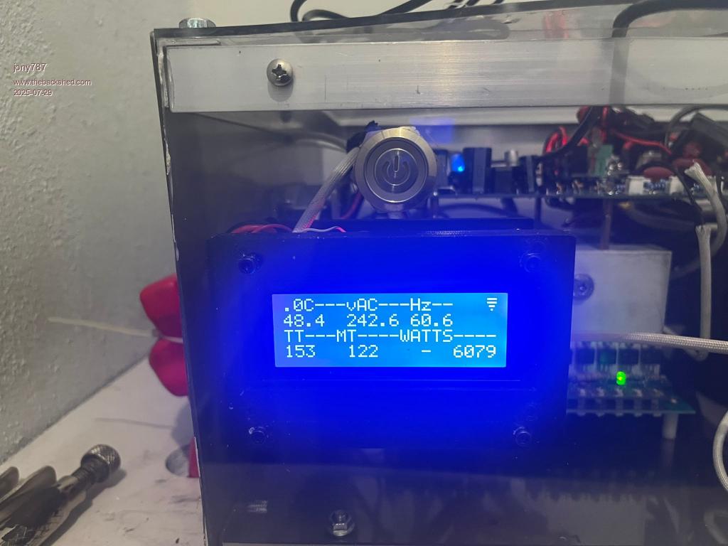 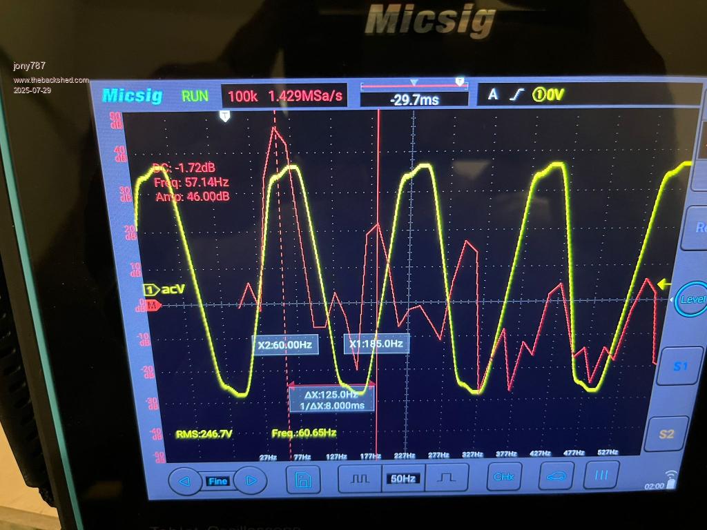 Because it is  . . Grid profile I’m using: **Off-Grid FW60 PEL6000** (with a 6 kW export limit I requested as a secondary cap against my inverter). They also have the same profile without the limit: **Off-Grid FW60**. Edited 2025-07-29 01:41 by jony787 |
||||
| analog8484 Senior Member Joined: 11/11/2021 Location: United StatesPosts: 204 |
Nice to see the improved voltage waveform. Thanks for sharing the grid profile. |
||||
| The Back Shed's forum code is written, and hosted, in Australia. | © JAQ Software 2026 |
