
|
|
Forum Index : Electronics : Struggling with inverter build
| Author | Message | ||||
| Dev7 Newbie Joined: 15/10/2025 Location: South AfricaPosts: 3 |
Hi all, I am designing a sine wave inverter using a full bridge, low frequency transformer (E-core) topology. I am using 20kHz SPWM generated by an Arduino Nano. I have seen many low power inverter schematics such as the one on the EG8010 datasheet directly connecting a 2.2uF capacitor across the secondary of the transformer and using the leakage inductance of the primary to filter out the 20kHz SPWM. However, from what I have read on this forum, it seems a correctly sized choke is needed between the H-bridge and the low frequency transformer? I am struggling to correctly design the stage after the H-bridge. What would be a suitable inductance for a choke on the primary of the transformer and is a 1uF or 2.2uF capacitor better suited for the transformer secondary? Specs: Input - 12V DC Output - 230V, 50Hz Power - 230VA Schematic is attached. I can also upload my code if needed. Please let me know if you see any obvious flaws in my design. 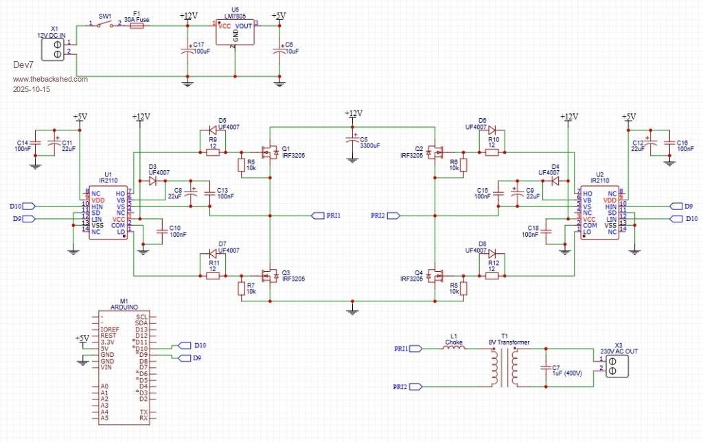 |
||||
| analog8484 Senior Member Joined: 11/11/2021 Location: United StatesPosts: 204 |
For that low power level the leakage inductance may be enough. |
||||
| KeepIS Guru Joined: 13/10/2014 Location: AustraliaPosts: 2196 |
My testing has been with Toroidal transformers only, not E-Core. For toroids, the secondary cap value is normally 3.3µF to 4.7µF but is not critical, as analog8484 posted, you may require less. A Primary choke value of around 42µH in total, ideally wound on a number of stacked Sendust Toroids in order to attain the required saturation current and Inductance for a given Inverter is the way to go in Toroidal Inverters. From memory a few builders have used E-cores in their inverters and found a good reduction in Idle current with the choke. NANO:Inverter V 8.2ks - Linux AvrDude GUI script V4.1 |
||||
| tinyt Guru Joined: 12/11/2017 Location: United StatesPosts: 561 |
How do you regulate ouput voltage? |
||||
| nickskethisniks Guru Joined: 17/10/2017 Location: BelgiumPosts: 481 |
Leakage inductance is higher on e-cores because of the shorter winding path you have, in a toroidal core it's longer so primary and secondary are better coupled. You are also using 12V so the needed filter inductance will be lower then in a 48V inverter. The amps are higher so you end up with the same core dimensions then a 48V inverter with the same power output. Edited 2025-10-17 16:39 by nickskethisniks |
||||
| wiseguy Guru Joined: 21/06/2018 Location: AustraliaPosts: 1297 |
My experience as a rule of thumb starting point is 1uH per volt. So for 12v ~ 12uH, because you are not using a toroid maybe 5 - 10 uh is sufficient. If at first you dont succeed, I suggest you avoid sky diving.... Cheers Mike |
||||
| Dev7 Newbie Joined: 15/10/2025 Location: South AfricaPosts: 3 |
Thanks for the replies guys. I am hoping the leakage is enough to act as a filter on its own, but will be testing. How does leakage inductance change in relationship to power? Is it just the fact that bigger more powerful transformers tend to have lower leakage and hence require a suitable choke? KeepIS, this is very helpful info, thanks. This gives me a better idea of the component values I should be looking for. Plan is to test with a 1uF, 2.2uF and 3.3uF to see which yields best results (without a choke). As for the choke, I have ordered a singular toroidal core to experiment with (picture attached). I am hoping it is of suitable size and has the correct properties so that I can wind my own. Tinyt, I forgot to add that part into the schematic. My idea was to use a ZMPT101B AC voltage sensor module directly connected to the 230V AC output and feed that into the ADC of the Arduino Nano. Then, regulate using the modulation index in code. I have not seen anybody use this module before so I will have to experiment and see if it works. Is there a better/easier way to regulate the output voltage? One more question. I am using bipolar SPWM instead of the typical unipolar SPWM that is used on the EG8010 chips. Besides higher switching losses, is there a major downside to using bipolar SPWM? Thanks. 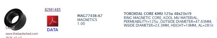 Edited 2025-10-17 17:02 by Dev7 |
||||
| analog8484 Senior Member Joined: 11/11/2021 Location: United StatesPosts: 204 |
The effective inductance gets lower with higher current/power due to saturation current limits. |
||||
| Dev7 Newbie Joined: 15/10/2025 Location: South AfricaPosts: 3 |
I have got my circuit board up and running and connected it to the transformer. These are the results I obtained. 230V AC 50Hz sine wave with no load is obtained at the output (image attached). Unfortunately, when loaded with a 30W incandescent bulb, voltage drops all the way to 140V. Added another 30W bulb (60W total) and the voltage dropped to 70V. Battery voltage did not sag and stayed at ~12.8V which tells me that the power losses are most likely coming from the transformer. I scoped the transformer primary with no load, but I'm not sure what waveform I should be expecting. Scope image is attached. Why am I reading 68kHz on the transformer primary? Should I be seeing a sine wave on the transformer primary or is it normal to still see some un-filtered PWM? I attached my code. Let me know if any more info is needed. Any assistance would be greatly appreciated. Thanks. #include <avr/io.h> #include <avr/interrupt.h> #define SinDivisions (400)// Sub divisions of sine wave. 200=10kHz, 260=13kHz 300=15kHz, 360=18kHz, 400=20kHz etc static int microMHz = 16; // Micro clock frequency static int freq = 50; // Sinusoidal frequency static long int period; // Period of PWM in clock cycles. static unsigned int lookUp[SinDivisions]; static char theTCCR1A = 0b10000010; //varible for TCCR1A volatile double percentMod; void setup(){ double temp; //Double varible for <math.h> functions. period = microMHz*1e6/freq/SinDivisions;// Period of PWM in clock cycles for(int i = 0; i < SinDivisions/2; i++){ // Generating the look up table. temp = sin(i*2*M_PI/SinDivisions)*period; lookUp[i] = (int)(temp+0.5); // Round to integer. } // Register initilisation, see datasheet for more detail. TCCR1A = theTCCR1A; TCCR1B = 0b00011001; TIMSK1 = 0b00000001; ICR1 = period; // Period for a switching frequency of 10KHz on a 16MHz crystal with 200 subdivisions per 50Hz sin wave cycle sei(); // Enable global interrupts. DDRB = 0b00000110; // Set pin 9 and 10 as outputs. percentMod = 0; for (int i = 0; i < 50; i++) { // Soft Start (3 seconds) percentMod = percentMod + 0.01; delay(60); } } void loop(){;} ISR(TIMER1_OVF_vect){ static int num; static int delay1; static char trig; if(delay1 == 1){ // Delay by one period because the high time loaded into OCR1A:B values are buffered but can be disconnected immediately by TCCR1A. theTCCR1A ^= 0b10100000;// Toggle connect and disconnect of compare output A and B. TCCR1A = theTCCR1A; delay1 = 0; // Reset delay1 } else if(num >= SinDivisions/2){ num = 0; // Reset num delay1++; } // change duty-cycle every period. OCR1A = OCR1B = int(lookUp[num] * percentMod); num++; } |
||||
| phil99 Guru Joined: 11/02/2018 Location: AustraliaPosts: 3317 |
The MOSFET H-bridge is applying a modulated PWM signal to the primary. The scope is doing its best to show that but there are too many PWM cycles per 50Hz cycle to display properly. The 68kHz can be ignored, the modulation is confusing the scope. Add a low pass filter between the primary and the scope and you will see a sine wave. Try 10kΩ in series and 100nF across the scope. If you get 7 to 8 Vrms on the primary with a 100W load the the H-bridge is doing it's job and the low secondary voltage could be due to the type of steel used for the laminations and/or the thickness of the laminations. At high frequency the laminations need to be very thin to minimize eddy current losses. For RF powdered silicon steel is used to keep losses down. If that is the problem, keep the PWM frequency out of the transformer by adding a suitable series choke and capacitor across the primary instead of the secondary may be needed. The capacitor may need to be quite big, perhaps 100µF or more. Some experimentation will be needed with that and the number of turns on the choke. A bi-polar electrolytic would keep the size down. If the primary voltage also sags in a similar ratio as the secondary sag (loaded V/unloaded V) then the issue is with the voltage feedback not compensating for the load. . Edited 2025-10-19 06:32 by phil99 |
||||
| analog8484 Senior Member Joined: 11/11/2021 Location: United StatesPosts: 204 |
The voltage is dropping under load because your code doesn't appear to do output voltage monitoring or regulation. There are already some excellent basic Arduino SPWM inverter demos/tutorials on the web. I recommend you study them. Here is one example (it should be understandable with the English subtitles): https://www.youtube.com/watch?v=UAlHPy-uYwg Edited 2025-10-19 07:40 by analog8484 |
||||
| tinyt Guru Joined: 12/11/2017 Location: United StatesPosts: 561 |
If above is the code you have so far, it does not have the output voltage feedback to spwm modulation index you mentioned earlier. Include it and the associated circuit and re-do load testing. Edited 2025-10-19 07:53 by tinyt |
||||
| The Back Shed's forum code is written, and hosted, in Australia. | © JAQ Software 2026 |
