
|
|
Forum Index : Electronics : Spud
| Page 1 of 2 |
|||||
| Author | Message | ||||
oztules Guru Joined: 26/07/2007 Location: AustraliaPosts: 1686 |
Ok, here are the piks you needed to see 
Here is the unmessed with supply with very little load ... ie less than 15W Notice it is not a square wave, and it gets worse with less load until it is just a mess. From this point on (more load), it turns into square wave. The interesting thing is that the drive wave from the chip is square, but the output from the totems is not...... It seems that as the output voltage is at set level anyway (capacitors keep it there against low drain), the pulse starts out well, but loses something in the totems... don't understand this. 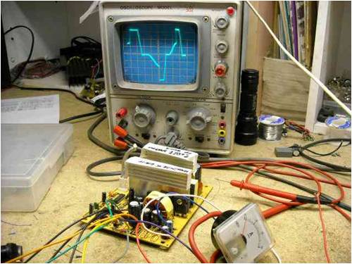
At this point I played with your first conversion, and decided that as I had no decent safe loads to drive ( I always use a very low impedance motor... which would blow this up), I would butcher this one completely. I pulled off everything on the low side except for the 494 and associated bits..... this included the voltage stabilization stuff for the aux supply.... It now looks like this.... notice the current limiting is in place as well to protect it from me. This is the first one I have played with that has an opto for the aux. By ripping out the opto, and placing a 270R resistor where it's high side pins were, we get a steady 15v for the 494.... but no 5v supply for you to use  ... I wanted to have no feedback interference to worry about. ... I wanted to have no feedback interference to worry about.
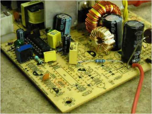
I replaced the inductor with a larger one while I was there, and used smaller caps on the output to give me more room to play. The current sense is as the circuit but with 330r 10n feedback not the 470n. At 7v almost 0 amps.. the wave form is just as sorry as the original.....: 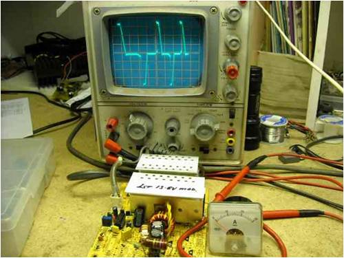
The good news is that as we wind up the voltage to 10v it looks like this... still less than 15W... so don't panic. 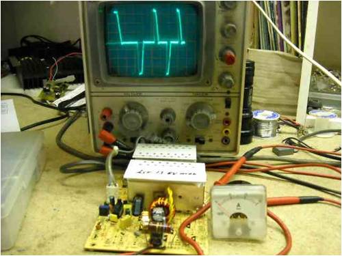
As we get to about 20W, we start to see a more normal type of wave. You must forgive the assymetrical stretch and upper and lower size... this scope is 30 years old... and is not even remotly accurate... but it gives me a good enough idea of what I'm looking for. It rises steeply, and drops off at an angle.. I think this is real.. but it could be the stretching in the scope. 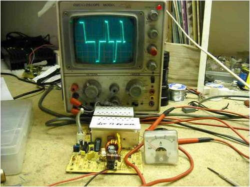
At 25v and >1A (maybe 30W) it looks like this .... note the stretching across the screen... 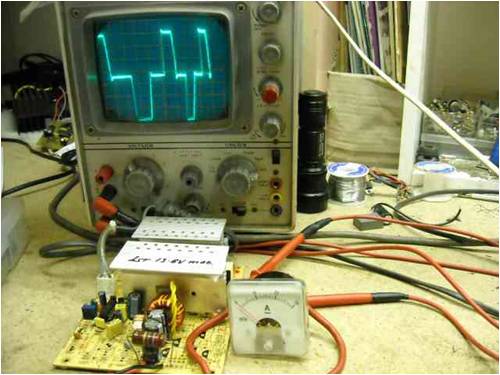
and at 30v maybe 60W, it's like this: 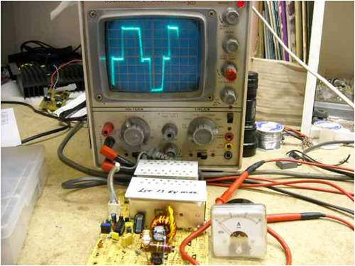
and peaked out is like this: 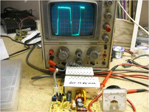
So if we use voltage control only on a high impedance load (about 10R) it looks like that. Now for the fun stuff, with the vac motor connected (maybe an ohm or so) and set down at about 5A and 7V (35W). 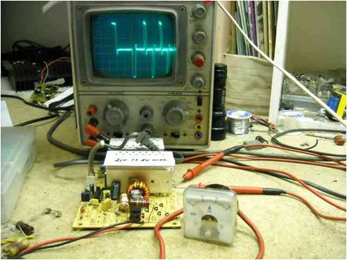
At 7A and 14v (100W) it looks like this: 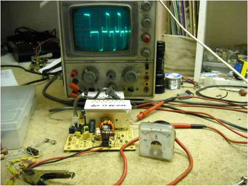
If we pull the current and volts up to 260W 26v@10A then it gets to look like this: 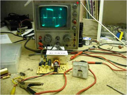
and >300W (30v@12A)looks to be the end of this with the present settings..... 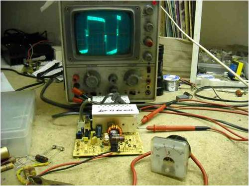
I have been eating yummy bikkies and drinking Mareeba coffee.... wonder where I got them 
Now that one is working I will see if I can tweek it more, but I thought you would like to know I have started Now I will do the second one, and see where the changes were made that made the difference so we can find the culprit. It was good to see that this supply had two wires joining the centertap to the earth point. I snipped one out and used the remaining one as the current shunt. well thats the first report. Hope it lifts your spirits some. ..............oztules Edit: Notice I said about 10R for the high impedance load... that's because the resistors smoked up a bit when under higher loads.. so they increased their resistance some... like this: 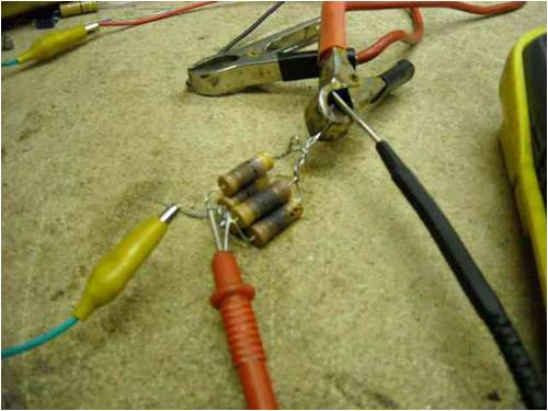
and i put in a 2 pin 240v intput plug... so i can swap between boards quickly Village idiot...or... just another hack out of his depth |
||||
philb Regular Member Joined: 05/07/2008 Location: United StatesPosts: 96 |
Thanks for the post oztules. This has been interesting and enjoyable. When I get caught up on must do projects, I intend to get back to power supplys and larger power square wave units discussed in earlier posts. Sometimes it doesn't hurt to wait by the mailbox. philb |
||||
| sPuDd Senior Member Joined: 10/07/2007 Location: AustraliaPosts: 251 |
G'day Oztules, first up thankyou very much for spending the time to enlighten myself and the other board users. It's highly appreciated. Some questions: You probably noticed how quickly the sinks heated with the original sloppy wave. How did they compare once you fixed the aux supply to 15V? I also considered turning the aux up to about 15V just to make sure the 494 ran at its best. I'm still confused by how you managed to get a clean wave by just turning up the aux supply. I considered reducing the limiting resistor value (normally about 1.5K) that feeds the aux 12V to the centre of the drive transformer, but was worried it would just saturate. Having said that, isn't that the job of the single turn that goes through the drive transformer - to saturate (stiffen) the base drive? I'm surprised you have never seen an opto system on the aux before, I've not seen one without yet. The aux is a funny system in that it relies on the self oscillation of the aux transformer while being voltage controlled across the opto. A higher 5V aux would be OK, as I intended to use a 7805 for my PICAXE. I don't intend to get the units back, its not worth the freight and I have an unlimited supply (pun) of units here. So feel free to run any old load on them. I find old toasters have great mica cards with resistance wire on them. You can slide an alligator clip up and down them for total load control. Looking forward to further autopsy, sPuDd.. It should work ...in theory |
||||
| oztules Guru Joined: 26/07/2007 Location: AustraliaPosts: 1686 |
Hi Spud. "You probably noticed how quickly the sinks heated with the original sloppy wave. How did they compare once you fixed the aux supply to 15V? " I didn't really look at the first supply in operation, other than to see that it worked (no blown trannies etc). As I had two conversions, I decided to lay waste to this one as if I was starting from scratch... That way I would not follow any problems that I had not noticed, and would prove to me that it would do as I said it should.... and it did. The first photo was of your unmodified unit... original condition, just to show that under less than 15w, the original was no good either... but obviously improved with load very nicely. I'm not sure that the 15v was instrumental to the improvements, but was part of the rebuild... I just like a bit more voltage... just me. I wanted to make sure I had no interferring fluctuations which may have been from the regulation of the aux.... so thats why I ditched the opto system... and it gave me an empty board on the LV side. Heating.... at less than 120w, you could get away with no cooling I suspect, temp would run at about 50-60 degC... just a little uncomfortable to touch, but not much more.. we need to rid ourselves of a good 50 watts in the system from what I hear of the efficiencies of these things. If the wave is bad, it will over heat at much lower power levels. I will do some testing of the second conversion supply, and try and find out what really happened with the conversion. I know it will work now, just a matter of step by step elimination I guess. "I don't intend to get the units back,".... you mean I get the bikkies and the units too???... spoilt me. ....Till later (farm work to do now) ...........oztules Village idiot...or... just another hack out of his depth |
||||
| sPuDd Senior Member Joined: 10/07/2007 Location: AustraliaPosts: 251 |
I'm not clear what changes between original and mod, its almost the same, just less voltages to monitor. I'm still suspicious that the original setup used some trickery around the comp or DTC pin. Take a look at the setup on the original unit. Did you observe the poor wave of my mods? In particular what looks like false triggering from the opposite half of each drive. Thought you might like the offerings from our sunny highlands
sPuDd.. It should work ...in theory |
||||
| oztules Guru Joined: 26/07/2007 Location: AustraliaPosts: 1686 |
"Did you observe the poor wave of my mods? In particular what looks like false triggering from the opposite half of each drive. " In a word ..... yes. So I sat there tonight (haven't had a chance to work on it since monday... sorry) and pondered this question while looking at the backshed site ... at this question. And then it hit me. If we have a wave form going from 0 to max, and we are looking into just a diode and a capacitor.... we will have terrible harmionics and crest factor. The capacitor will do nothing for the most part (low load) as it is above the wave voltage. As we get cap V= output V,the cap starts to draw all it can... max current. As the voltage rapidly (instantly if no real load) becomes to V max (as determined by the feedback circuit) .... the current stops flowing, and gently collapses into no load... guess what this looks like. A weird triangle at best or a hash if the harminics get into it through lack of load to absorb them..... which is what happens. Perhaps that is why the picture looks best when the wave is full duty cycle... the transformer is at saturation (which seems to be the upper limit case), and draws current when the cap would otherwise not, and there is no feedback in the sense circuit (we are at full duty cycle), so it cant interfere with the 494, pulse train, and the saturation also helps mitigate/crush the hash. Thinking about your tiny inductor you put on, it probably behaves as a diode and a capacitor only, it would barely see the inductor. With this in mind I'm off and out to the shed......... Well, I grabbed a former toroid with about 35 turns on it, and replaced the inductor, and the caps (too low voltage you had on there... one is now in orbit). Actually I only used 1 cap, and didn't bother with the second one (on the output itself). It is exactly as you sent it. (#2).The only change is the inductor and the cap. (1000uf 63v)... so no real difference except the voltage and smaller uf.... and the 2 pin plug thing. It looks like this: 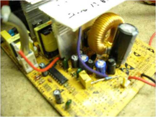
Now...( with impish grin), your gonna kick yourself when you look at these pics...... Here we are at 7W .........7V7 @ 1A 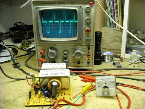
and at 20W ...... 10V7 @ 2A 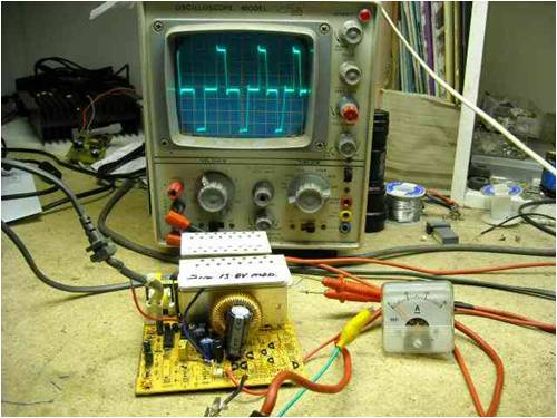
at around 100W ... 20v 5A 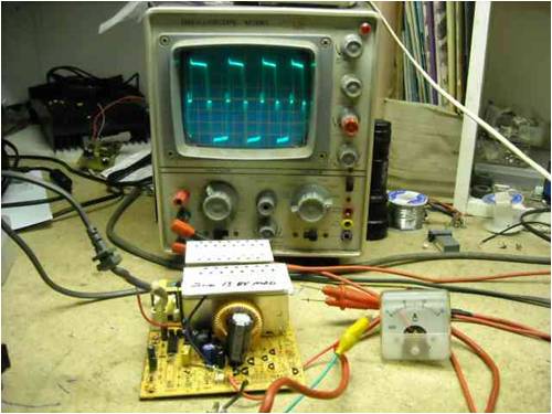
and 120w 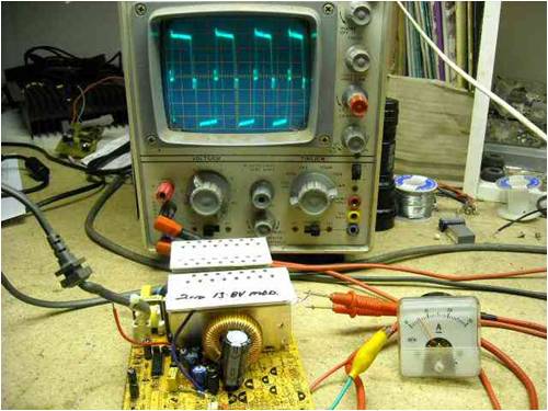
So go and do a conversion, and wind different inductors... it will solve your problems. There's a tsumnammi coming apparently, best check what is going on. ............oztules Edit: It's only a marine warning, the shaky islands seen to have had a 7.9 shake. Will hit here after 10.00pm. Village idiot...or... just another hack out of his depth |
||||
| Dinges Senior Member Joined: 04/01/2008 Location: AlbaniaPosts: 510 |
Oztules, Oztules he's our man - if he can't do it, no one can! 
And all on a diet of cookies and coffee... |
||||
| oztules Guru Joined: 26/07/2007 Location: AustraliaPosts: 1686 |
Thanks Dinges for the accolades, but I just have lucky days.... if I knew what I was doing I'd be dangerous. It actually came about from the discussion we were involved in regarding power/crest factor when charging a battery or driving the front end of PWM units. Strangely and looking at it now, the inductor you spoke of seems to fit in here.... which I only just realised as I typed this . If I were a bit brighter I should have realised earlier  .... but I got some chocky chip cookies and good coffee for being a bit slow .... but I got some chocky chip cookies and good coffee for being a bit slow  .... and a few nice power supplies... thanks Spud. .... and a few nice power supplies... thanks Spud.
Now, Spud, If you want to straighten up the trailing edge of the "square wave" shown best in the 7 watt photo (see it's even better than the original supply down at these levels too )...
Simply replace the damping capacitor and resistor (103 capacitor and 10ohm resistor in series across the secondary) with a 47R and a 1n capacitor. This will result in a near perfect sided square wave, and run a bit cooler too.... seems to run ok all the way up to 120w. Will see when the current control is in place if it affects the upper end (300W+) or not... it won't get rid of that little "spike" at the top of the leading and trailing edge though. I couldn't take this supply any higher in power... as my resistor bank started cooking quite nicely at 120W. When I put the current limit circuit on, I will be able to drive it to full>300W and see the heating. It ran maybe 45 degrees C up at the 120W mark ....although 3-4 min was as much smoke as I could stand from the resistor bank though. So we didn't just equal the waveform of the original supply down low, but I think easily bettered it Have fun with it ..........oztules Village idiot...or... just another hack out of his depth |
||||
| sPuDd Senior Member Joined: 10/07/2007 Location: AustraliaPosts: 251 |
This is the reason why I gave it to you, for a second opinion. You know what its like. Try to get a diesel genset started for hours, when someone shows up and asks why the emergency stop button is pressed in. OK, the thing for me to do is try another mod this weekend. Test before & after. Follow your method, make it work. Then ruin it by using the original inductor and a two stage cap filter. After all, that�s what science is. Anything that can be reproduced time and time again. I stripped down a carton of PSUs the other day, and filed them in a plastic container. I shall select a victim and proceed. 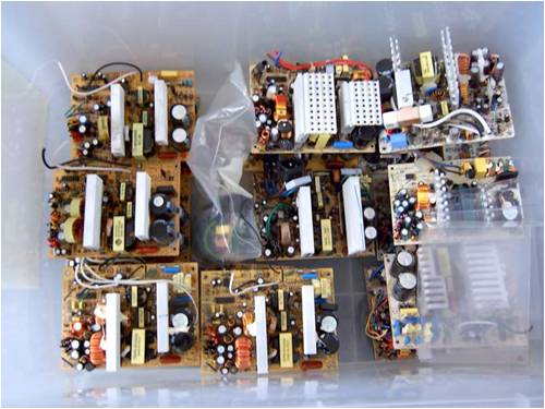
I'm grateful as always and hope as a non-coffee drinker I choose something to your taste  especially for these chilly nights. especially for these chilly nights.
sPuDd.. It should work ...in theory |
||||
| oztules Guru Joined: 26/07/2007 Location: AustraliaPosts: 1686 |
You appear to have many hours of entertainment ahead of you by the looks of it.... lots of fun. Glad I could help in some way, and thanks for the goodies. The council dropped off the Islands bitumen spraying truck, to see if I could fix up the computer that monitors and regulates the tar spray rates (hopefully I can).....but, they told me that there are about 8 computers down at the tip (from the local school).... so I must hasten down there and snaffle them before they get mangled. Then I too should have a box of psu supplies.... and video monitors with flyback supplies.... I hope ..........oztules Village idiot...or... just another hack out of his depth |
||||
| sPuDd Senior Member Joined: 10/07/2007 Location: AustraliaPosts: 251 |
And HDDs, and mobos, and so many other useful bits
Edit: Looking right back to the first post, the fact that the un-modded PSU runs crappy until there is a decent load on it supports my theory about the cheapness of some models. It explains why they use a 120mm fan on a 250W PSU. At low loads it creates more waste heat than output power. Then again, what do you expect for a PSU that retails for $30 !! 
sPuDd.. It should work ...in theory |
||||
| Dinges Senior Member Joined: 04/01/2008 Location: AlbaniaPosts: 510 |
Stumbled upon the link below the other day. Someone has developed a very simple conversion for PC PSUs, to drive them with 12Vdc input (instead of 230Vac). This method should work too for 24 and 48Vdc input power: http://www.dasilvas.info/ATX%20Power%20supply.htm 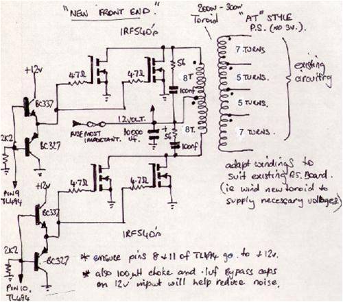
Basically, he takes out the entire input section, including transformer. Rewinds the transformer (or simply takes a large toroid he wound) and adds low-voltage/high-current switchers (IRF540 MOSFETs), driven directly by the outputs of the TL494 via totem-pole drivers. Haven't tried this out myself yet, but intend to do so when time allows. Can't get much simpler than this. Could also be turned into a simple boost-converter for windturbines, perhaps? Input 12V, output 24V (on the 12V line), or even 48V by cutting the groundlead of the secondary and full-wave rectifying the + and - 12V lines (yielding 2*24V). The only limit with those PSUs seems to be one's imagination.... Hope the above is of use to others too. Peter. |
||||
| oztules Guru Joined: 26/07/2007 Location: AustraliaPosts: 1686 |
Neat. I assume the input and output sides share common grounds. It needs another * note. The 494 will need bootstrapping as it no longer has the unstable front end to trickle start the secondary for the Vcc for the 494 Or simply put, 12v to pins 8 (collector 1),11(collector 2). and 12 (vcc) After startup, vcc can come from the output if you wish, and the rectifying diode will isolate the 12v proper.(though I would just use the 12v and cut the power from the secondary system anyway) I don't see the totem poles acting as a multivibrator to get startup....so no bootstrap.. but I've been wrong before too. .............oztules Village idiot...or... just another hack out of his depth |
||||
| Dinges Senior Member Joined: 04/01/2008 Location: AlbaniaPosts: 510 |
He basically feeds the TL494 straight from input power - no bootstrapping required. And yes, downside is that there's no galvanic separation between inputs and outputs as ground is shared. I'd also remove the components on the secondary side that normally power the TL494 after startup, as you suggested. If galvanic separation were a requirement, I'd probably feed the TL494 straight from its own small DC-DC power converter (with floating output ground). That way you get the total galvanic separation on input and output, and no bootstrapping required. A simple DC-DC brick module would be all it takes. Peter. |
||||
| Dinges Senior Member Joined: 04/01/2008 Location: AlbaniaPosts: 510 |
Oztules, I have another PC PSU related question, if you can spare the time. I'd be very interested in your take on things, especially w.r.t. to the PC PSU option.... I'm toying with the idea of building a micro-TIG welding machine (basically plain TIG, but for delicate work, welding currents 0.1-10A). A modified PC PSU seems to be just right for this kind of thing, with a voltage of about 18-20V and a current of 10A max. (for anything more substantional I'll fire up the 250A AC/DC watercooled TIG machine, but she doesn't work very well below about 8A....) At the moment I'm considering two possibilities: using a 24V transformer with switchable resistors to set the current in a range of .1-10A (two old transformers from a UPS in series, 13Vac output each at some 20-odd amp�res). The advantages: switchable between AC and DC (easy to wire in a switch that will insert/cut-out the rectifier), robust, simple. Foolproof and indestructable. As the plan is to add HF start too, there are no sensitive electronics that can go defect by a few kV of RF modulated on top of the +12V line. Cons: not easy to modulate the current electronically, so will be hard to provide up-slope and down-slope (i.e. slowly ramping current up from zero to the set welding current, and down again). Also very hard to implement pulse-mode (i.e. modulating the welding current between two user-settable values) The other option is using a modified PC PSU, which seems to be perfect for the job. It should be possible to modulate the current from 0A to the set value, and down again at the end of the weld. Downsides are that there is only the option of using DC (hm.... on 2nd thought... maybe AC *would* be an option, by tapping power straight from the transformer output, before the rectifiers? Would be AC at a few kHz though, and square wave too (even better than sine for this purpose!). Not quite sure how the several 10s of kHz of AC would work.... must ponder this a bit more. Anyway, my question to you: if using a PC PSU, how would you incorporate up-slope/down-slope. I.e., assume that we have set a current of 5A using the normal method via the Oztules' current modification. Now, when the weld is to be started, the current is to be ramped up from 0A to 5A over a user-determined time (from about .5-3s with a user-adjustable timer; same for down-slope at the end of the weld). I've been pondering how to do this ramping up and down, either by injecting a signal in the current opamp in the TL494, or via the dead-time control (DTC), pin4 of the TL494. Thinking aloud here and interested in your opinion on the matter of modulating current of a PC PSU. How would you go about it? Again, not sure that I'll go the PC PSU route, as it would take quite a bit of filtering to prevent the HF arc start (RF high voltage) from messing with the PC PSU. But the advantage of up/down slope and the option of implementing pulse-mode (i.e. modulating the weld current at a few Hz between two values) make the PC PSU seem attractive again. Peter. (trying to juggle all those interesting projects in to limited time - induction heater, spotwelder, microTIG, oh, and a 10hp conversion that's still waiting to be finished.... on the bright side, when I'm retired I'll have all the time in the world, right?) |
||||
| oztules Guru Joined: 26/07/2007 Location: AustraliaPosts: 1686 |
Hmmm, I'm inclined at first blush to leave the V and A circuits alone, and use the pin 4 route. A simple 5v+ through a resistor (time 1) to drive pin4 (and a capacitor to ground for timing) will hold it high (off). Perhaps through the contacts of a NC relay, and when you press the trigger, the NO contacts of the relay short the pin4 to ground through a resistance (time2) (on). So a double throw, single pole where the common is to pin4 and the nc and no contacts to +5v and gnd respectively through your timing resistors... and a cap on pin4 for the timing. This will pull it down softly to full on (zero pin 4) when you pull the trigger to go. Release the trigger, and the relay opens and drives the first resistor to charge up the cap and pin 4 goes high till next trigger... or use a flip flop etc. This will give you full control of both times via the resistor selection (and say 10uf capacitor). I like the relay idea, as you will hear it click in (find a noisy one)... so you mentally get ready for the zap. Flip flop will probably appeal to you though.
.............oztules Village idiot...or... just another hack out of his depth |
||||
Greenbelt Guru Joined: 11/01/2009 Location: United StatesPosts: 566 |
DINGES Quote:, Cons: "not easy to modulate the current electronically, so will be hard to provide up-slope and down-slope (i.e. slowly ramping current up from zero to the set welding current, and down again). Also very hard to implement pulse-mode (i.e. modulating the welding current between two user-settable values)" Dinges: I found this on the net. There are a few possible Ideas here, .The Foot pedal to ramp the current, Up-Down Although an Auto alternator is used as a power supply , I Think the control circuit would be functional with any filtered power source so long as Component values are suited to the lower output design. If nothing else, This Guy does good looking work. When/if you decide to tackle this project, Keep us posted. Edit: fixing the links. http://myweb.cableone.net/rschell/TIG_MicroController%20Regu lator.htm I found this on the Net Home page Time has proven that I am blind to the Obvious, some of the above may be True? |
||||
| Dinges Senior Member Joined: 04/01/2008 Location: AlbaniaPosts: 510 |
Thanks for the response, Oztules & Greenlink Oztules, had an already modified PC PSU lying in the attic which I had modified in the past for variable voltage and a current limit of 13A. When supplying a variable voltage (by a potentiometer) of between 0 and Vref, output voltage can be nicely controlled between minimum and maximum (2.5-28V). Works very nice. But when I short the outputs of the PSU and try to modulate current, there's no real control - below a certain setting of the potmeter, current is zero, and the slightest bit above the threshold current goes to maximum (13A). It can't really be controlled with the deadtime voltage. Strange, but one thing is that I didn't modify the current control properly, as this PSU didn't have a 'flying lead' at the transformer. Not sure exactly *what* I did back then, but I'll modify it to 'standard Oztules' configuration and try again. Current should be properly variable, just like voltage, me thinks. Have been thinking about up/downslope too and agree, a simple RC network would be more than enough - upslope doesn't have to be a perfectly straight ramp up, a logarithmic rise would be just as good for this purpose. It'll take a bit of fooling around with timers though to get the proper sequences - when trigger is pressed, gas flow should start immediately. After a user-settable time (pre-flow), weld current should ramp up. When welding is stopped, current should ramp down. After current has ramped down, post-flow timer should keep the gas flowing for a user-settable time. 
Will take a bit of fooling around on paper designing circuits, but am sure I'll get that to work properly - without resorting to fancy microcontrollers. As far as the relay goes, the loud 'clunk' of the gas solenoid should provide more than enough audio feedback  . .
Greenbelt, was familiar with that design. Notice he uses a car alternator - nice if you want a 100+A rig, but that's not what I'm looking for. A car alternator requires different control, of the field strength. The point is to be able to do work like this: 
2 stainless M3 rings, welded together with 3 tiny TIG spotwelds. A continuous bead along the side wasn't possible as the work overheated, and I couldn't turn current down anymore on this large machine (250A watercooled) - when the arc was struck, it immediately had to be extinguished again. My idea is to build a small machine that performs well in the 0.5-5A range, and may go up to 10A. 
Machines like this are commercially available and basically nothing more than a constant-current source PSU with a solenoid valve for gasflow and a bit of control. Peter. Edit: just let the magic smoke escape from the PSU, but I managed to put it back in. For some strange reason I had 2pcs. 2SC2625 in the parts bin. Wonder where those came from.... More edit: not sure if this constitutes a thread hijack, or a follow-up on-topic post. Not even sure Glenn approves of this kind of stuff (micro TIG) on a wind forum. |
||||
| oztules Guru Joined: 26/07/2007 Location: AustraliaPosts: 1686 |
Magic smoke.... I guess your sense resistance was miniscule to almost non-existent. Use a larger R in the center tap leg. This should give you much more definition, and a chance for the deadtime to have some control. The smoke means that probably noise was the signal that the current sense comparator was using as a reference for your current control....living on the edge I suspect. I remember marveling at the shortness of your "link" resistance when you mentioned it originally. I'm beginning to think that your current limiting in that case was more good luck than good management
..........oztules Ps.... the more you blow up, the better you get at fixing em .....at least that's what I tell myself each time I sent another power tranny into the after life
Edit. Because the input sense on the current op amp is such a low impedance, perhaps instead of controlling the deadtime, you could fiddle the reference voltage on that op - amp (fairly high impedance...easy to pull up and down) to get the same ramp result....yes? Village idiot...or... just another hack out of his depth |
||||
| Dinges Senior Member Joined: 04/01/2008 Location: AlbaniaPosts: 510 |
[quote]I guess your sense resistance was miniscule to almost non-existent. Use a larger R in the center tap leg.[/quote] Guess again. :-) The sense resistance is small, but current control worked perfectly, at least at high currents (12-13A). Had set it with a fixed value (180R feedback resistor instead of 2k pot) to 13A. As sense resistor, I used the PCB trace....you can see a thin black wire from where the ground lead leaves the print to the TL494. That provides the ground signal for pin 16. The negative feedback from the sense resistor (i.e. PCB trace in this case) is taken directly at the common-pins of the transformer. No extra wires needed, all I did was create a new ground level signal by adding a black wire from the output ground to pin 16 of the TL494, see image below. 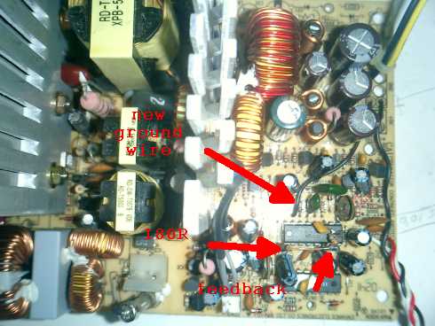
But this morning as I got out of bed the problem hit me.... I had opened the 180R feedback resistor and inserted a resistance decade to play around with the feedback value a bit. Now, when I built this decade a few years ago I *specifically* wanted break-before-make switches in it. 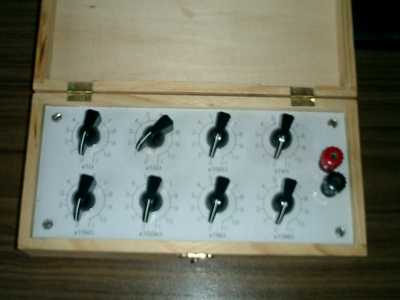

(the little clown, he cheers me up when I'm down) Well, when I shorted the output and plugged the PSU in, I briefly measured 20A so I swiftly reduced resistance by lowering the resistance of the decade. I guess you can guess what happened as I switched resistors... the feedback loop was briefly opened (break-before-make....), with described results. PSU fuse blew and house-breaker tripped. Switcher transistors had magically converted themselves into small-value resistors, but two exact replacements (2SC2625) were found in the parts bin. Felt a bit like a surgeon doing a donor organ transplant, inserting bits from a deceased (and long since gutted for parts) PSU into the patient on my work desk. But you're right, I'll increase the value of the sense resistor and a potmeter to make current user-adjustable down to a few 100 mA. oh btw - the original PSU is still going strong! Don't know how I've abused that thing over the past 2 years, but is literally indestructable: 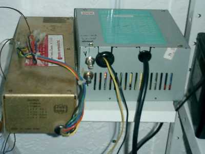
To the left of it my 'old' PSU (from an Apple II) that I've been using since 1993 as my power supply. +12, +5, -5 and -12V. Served me well for all those years, but ever since that modified PC PSU has appeared in my 'lab', it has been gathering dust. ...what you don't see are 6V and 12V batteries that often back up as quick-and-dirty power supplies.... Peter. (<-- who thinks Oztules has a very wrong idea of Dinges' level of sophistication....) |
||||
| Page 1 of 2 |
|||||
| The Back Shed's forum code is written, and hosted, in Australia. | © JAQ Software 2026 |
