Notice. New forum software under development. It's going to miss a few functions and look a bit ugly for a while, but I'm working on it full time now as the old forum was too unstable. Couple days, all good. If you notice any issues, please contact me.
GleamBright Regular Member Joined: 21/04/2025 Location: AustraliaPosts: 43
Posted: 01:43am 22 May 2026
Copy link to clipboard
Print this post
This thread has been started for discussion related to Aussie based builders of DIY 150V 45A mppt controllers, development of which is discussed in an associated thread '... roll your own', so as to avoid clogging up the excellent and advanced discussion in that thread. This is to allow for amateur/novice level discussion of all matters associated with these controllers from theory to build practise. Most current builders are also, ambitiously, building Wiseguy Inverters. Constructive input is invited from expert and experienced builders.
poida Guru Joined: 02/02/2017 Location: AustraliaPosts: 1485
Posted: 02:08am 22 May 2026
Copy link to clipboard
Print this post
Best of British Luck to you all.
my advice:
1 - obtain a DSO, new ones are reasonably priced and will go a long way in both learning how to avoid blown up FETs and choosing an adequate choke for both mppt and inverters.
2 - a bench power supply or two, such that 50V at 5A is possible. Ones that have current limiting is needed.
choke design is very much "use what you got" but test it to ensure it will work at the power levels required.
3 - make a choke tester. it will use the DSO. and the bench supply. You will discover during testing of the chokes how much power is possible before saturation. In fact, making the tester and using it will develop a large part of the skills needed for all this.
4 - get a decent DVM and leads. make some long leads with alligator clips to suit the meter. this frees up hands to get somewhere safe. Consider also a UNI-T clamp meter that does DC current. We need to calibrate the mppt..
hope this helps.wronger than a phone book full of wrong phone numbers
GleamBright Regular Member Joined: 21/04/2025 Location: AustraliaPosts: 43
Posted: 05:53am 22 May 2026
Copy link to clipboard
Print this post
Dammmit I agree, but also didn't want to hear that! :-), as I and we are beginners. I have a Uni-T Clamp meter: that's a start. We need the power suppply for inverter commissioning, which only leaves the DSO & tester.
That being said, most of the chokes in my haul have already been tested on the other thread and are steel laminate, or we could just buy chokes with established performance parameters.
Am studying the former threads in detail and will make more notes about the tester and methods described there in detail, for now.
GleamBright Regular Member Joined: 21/04/2025 Location: AustraliaPosts: 43
Posted: 07:50am 22 May 2026
Copy link to clipboard
Print this post
Question directed to Revlac re: Aurora chokes. I'm now regretting pulling one of my two 5 kW Aurora chokes apart after seeing one in use, untouched, in your build thread. Not to worry because I have two more 3.6 kW units OTW, there should plenty nuff components there. I can rewind the bare choke as well.
Did you ever test that choke to saturation?
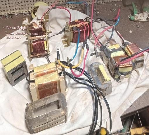
Picc of my choke candidates posted again for reference. I'll proceed with the build without the DSO in the interim, having confidence in my choke parameters.
Revlac Guru Joined: 31/12/2016 Location: AustraliaPosts: 1307
Posted: 08:36am 22 May 2026
Copy link to clipboard
Print this post
I didn't do a saturation test on the Aurora choke, didn't see the need for it as Poida and others tested and posted results of many chokes (not one of these that I am aware of) these were a little bit bigger cross section than the aerosharp cores and results should be marginally better. I still have one Complete 5Kw Aurora choke and will check it with the LCR tester (if it still works)when I get time tonight or in a few days orso, I need to build another charge controller anyway.
Edit: Ok found something I was looking for, The lab power supply I have is only 30v not relevant but it has a USB power supply to run the LCR meter to test the choke. I have photo's but you will likely do your own later so here are the numbers, The choke as is tested 517uH, now with the loop at the bottom cut One coil measures 157uH then join the 2 in parallel (as in the photo take not of which winding's are the inner layer and outer layer) I get 145.9uH You may wind your own but this is an easy start for a first build IMO. Edited 2026-05-22 22:22 by Revlac
Footnote added 2026-05-23 18:05 by Revlac I used a LC200A tester, old version without the case. Cheers Aaron Off The Grid
GleamBright Regular Member Joined: 21/04/2025 Location: AustraliaPosts: 43
Posted: 04:36am 27 May 2026
Copy link to clipboard
Print this post
Again a couple of questions:
- what wattage ratings are specified for the resistors? - What are the hole spacings and max diameters for the capacitors, excepting the large 470 uF capacitors on the main board (10mm/35mm)? I assume these can be obtained from the PCB layouts if not readily available.
Revlac Guru Joined: 31/12/2016 Location: AustraliaPosts: 1307
Posted: 08:25am 27 May 2026
Copy link to clipboard
Print this post
Capacitor typical lead spacing of 3.5mm 8mm diameter If not sure sometimes you can see typical size components on old Grid Tie Inverter's for reference Edited 2026-05-27 18:26 by RevlacCheers Aaron Off The Grid
Bryan1 Guru Joined: 22/02/2006 Location: AustraliaPosts: 2267
Posted: 09:28am 27 May 2026
Copy link to clipboard
Print this post
Years ago Poida put up a circuit to test a choke where it used a diode, a cap and a fet to pulse from an nano where a current sensor was put on the add to the scope picture.
Now I don't want to go off topic but my inverter has just gone past 80 Kw Hours and everything in my shed just works like using my mig @110 amps did break the 16 amp circuit breaker so a 25 amp one needs to go in.
As I did have both boards here I just had to try the first one that just works now I am on 24 volts and this MadBoard just works.
Now I did get a price on a 48 volt 600AH forklift battery where 5.5K aint a bad price so that is on my price list so I can power my shearing shed with this chinese Tip Top board that cost me $300.
So plenty of options mate
Regards Bryan
wiseguy Guru Joined: 21/06/2018 Location: AustraliaPosts: 1315
Posted: 02:25pm 27 May 2026
Copy link to clipboard
Print this post
The electrolytic capacitors on the MPPT power board are 35mm diameter, solder pins are "snap in", the snap in mounting hole centres are 10mm on the PCB. C1, C2 are 3.5mm All the ceramics are monolithic or film and are 0.2" or 5.08mm All resistors are 0.4" or 10.16mm
The resistors are all 250 - 500mW, but R9 & R10 should be 600mW - 1W but the hole sizes are only ~0.9mm so some resistors could be tight. I think for R9 & R10, I used 2 x 22R 400mW in parallel ie bend the pins as if either could insert into the board & solder one in parallel to the other just where the legs exit the body so you insert the piggy backed resistors as 1 part. From memory the resistors ran hot - they were an attempt to reduce emi, if they run too hot try reducing C18 & C19 to 470p but with at least a 63 or 100V rating.If at first you dont succeed, I suggest you avoid sky diving.... Cheers Mike
poida Guru Joined: 02/02/2017 Location: AustraliaPosts: 1485
Posted: 03:33am 31 May 2026
Copy link to clipboard
Print this post
my choke tester:
A simple thing to do, that will be a good exercise for the skills you need to build upon if you want to make your own inverter.
basic operating idea is to have a variable length pulse (5V) come out of the microcontroller and use it to switch a MOSFET completely ON and so put a voltage across the inductor under test.
My circuit uses a TLP250 opto coupler to obtain the required 12V drive to fully switch on the FET. 5V is not enough.
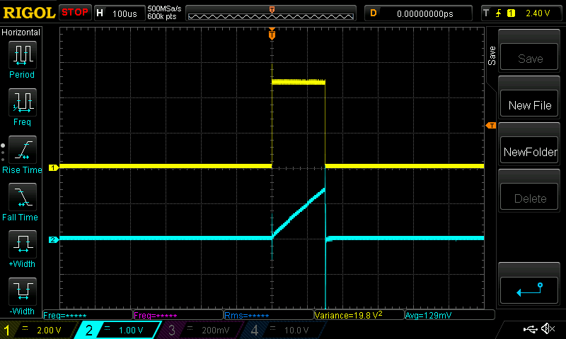
I need 2 signals, which are displayed on the DSO. Yellow trace is the 5V pulse from the Nano uC Light Blue is the voltage across a 0.02 Ohm resistor that is the last thing in the circuit that charges the inductor before Ground.
We could test the chokes (or inductors..) at far higher voltages but things are simple and easy when I do it with a 12V supply. eg. 2x the voltage is the same as 1/2 the pulse time.
The basic inductance equation used in testing the devices is L = V x t/I
L is inductance, in Henrys I is current, Amps t is time, seconds V is voltage, Volts
In practice, we will look for the change in current that occurs during a period of time.
I see the pulse length is 150 uS I also the the change in current is about 1.5V across the 0.02 Ohm current sense resistor. This is about 1.5 / 0.02 or 75 Amps (V = IR and of course I = V/R etc..) Volts is 12.1 V from the bench supply.
L = 12.1 * 0.000150/75 = 24.2 uH The BK Precision LCR meter has it at 24.6 uH The current increases linearly and in a nice straight line too.
I like to see measured results illustrate theory so nicely as in the above graphic.
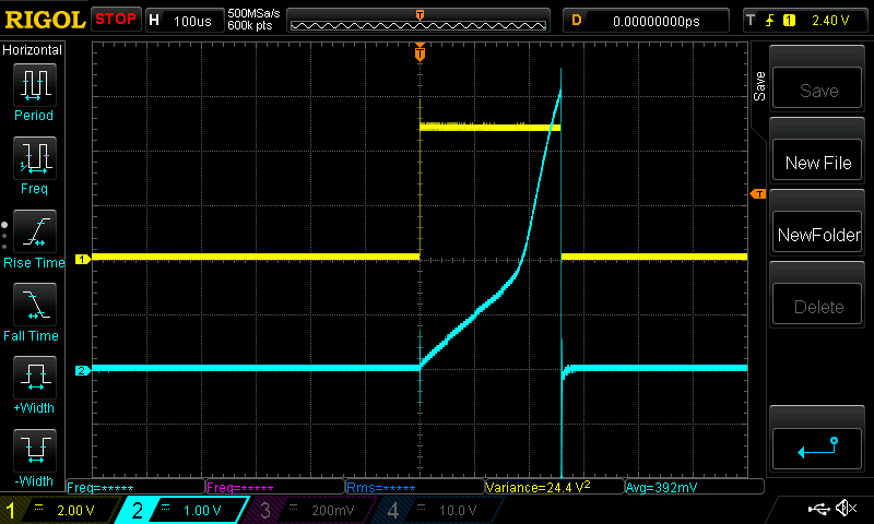
Now when I increase the pulse width a fair bit, we can see the current increase a lot faster over time after about 180 uS. This is when the choke is becoming saturated. It still IS a choke, with some inductance. But it's value will be a lot less than when it was not saturated.
260uS, 5V over 0.02 Ohms, 12.1V supply L = 12.1 * 0.000260 / 250 = 12.6 uH
GleamBright Regular Member Joined: 21/04/2025 Location: AustraliaPosts: 43
Posted: 04:12am 17 Jun 2026
Copy link to clipboard
Print this post
Can I put out a call for assistance please...
Does anyone have, or are able to develop, a detailed list of capacitors and resistors for the build - as based on Rogers' design? I've confirmed resistance and capacitance values from the schematics & layouts, but aren't yet confident enough in the specs to go ordering parts. Are any surface mount components needed (MLCCs or chip resistors) and what wattage, voltage, and leg spacing should we specify - by component?
It would save a lot of time and grief to have the info available so that we can confidently order what we need to advance the build.
The rest of the build has been identified and sourced and if it helps, this info will be made publicly available for those who may follow.
Alternatively, close up photos of the built PCBs.
KeepIS Guru Joined: 13/10/2014 Location: AustraliaPosts: 2265
wiseguy Guru Joined: 21/06/2018 Location: AustraliaPosts: 1315
Posted: 04:24am 18 Jun 2026
Copy link to clipboard
Print this post
Here is a PDF print of the Assembly drawing for Rogers version of the MPPT. I hope Roger does not mind me posting this on his behalf.
Assembly drawing MPPT-Roger.pdf Note: In the PDF, inside U1 is the missing designators from around the Nano as there was no room nearby to place them easily
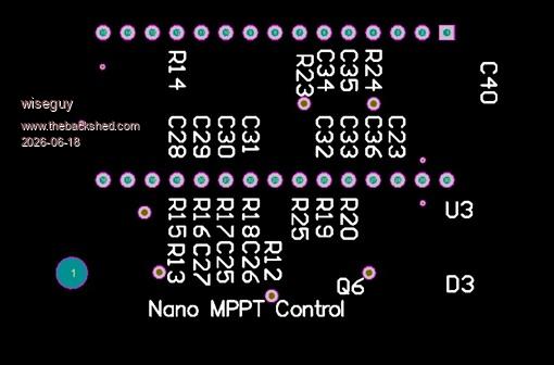
Below are the Nano SMD Designators on top of actual component positions - hope it helps
Note: C28, C29, C30, C31, C32, C33, C34, C35, C36, C37 are 1206 not 0805 - you may be aware of this. Edited 2026-06-18 14:59 by wiseguyIf at first you dont succeed, I suggest you avoid sky diving.... Cheers Mike
GleamBright Regular Member Joined: 21/04/2025 Location: AustraliaPosts: 43
Posted: 12:20pm 18 Jun 2026
Copy link to clipboard
Print this post
Thanks heaps Wiseguy. It was getting confusing there for a while as someone doing this for the first time, but I'm mostly across it now and on the home stretch.
With regards to capacitor voltage specs, currently running with 50/63V for the MLCCs (0805 & 1206 package). What voltage (s) would suit the electrolytics: 1000 uF & 10 uF?
Also, C18 & 19. These are 5mm spacing, through-hole. Would a simple MKT type suit?
wiseguy Guru Joined: 21/06/2018 Location: AustraliaPosts: 1315
Posted: 12:43am 19 Jun 2026
Copy link to clipboard
Print this post
C39 should be at least a 63V electrolytic it has to be a bit higher than the highest battery voltage, I would avoid ever running the MPPT with the battery disconnected as C39 could suffer. C38 is fine as a 16V. The 1000uF caps should be higher than the highest open circuit voltage that the solar panels supply. I am guessing that probably 150V - 200V minimum capacitor voltages would be fine. Some are using capacitors robbed from older grid feed inverters which are usually 400V minimum types.
For C18 & 19 I would use a disk ceramic with a minimum voltage rating of at least 250V. If the capacitors are physically small enough any voltage higher is ok ie 500 - 2kV such as Digikey D102K25Y5PL6TJ5R (500V) or S102K33Y5PP63K5R (2KV) @ 4c dearer!If at first you dont succeed, I suggest you avoid sky diving.... Cheers Mike
Bryan1 Guru Joined: 22/02/2006 Location: AustraliaPosts: 2267
Posted: 03:07am 30 Jun 2026
Copy link to clipboard
Print this post
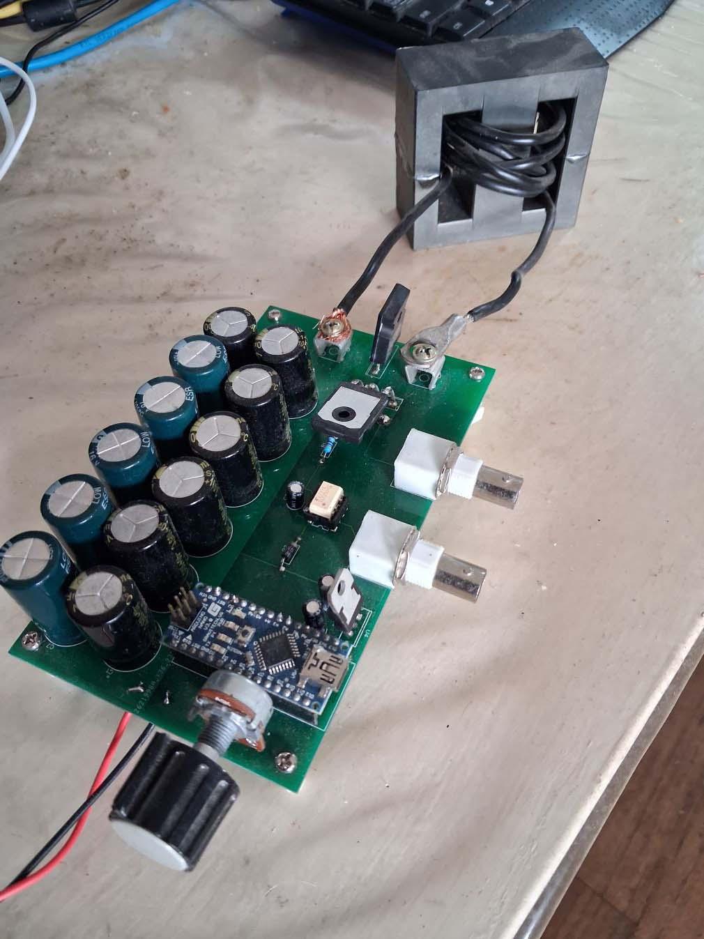
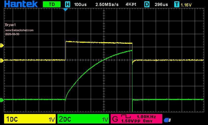
Well guy's that package finally came from element 14 so got my induction tester all finished
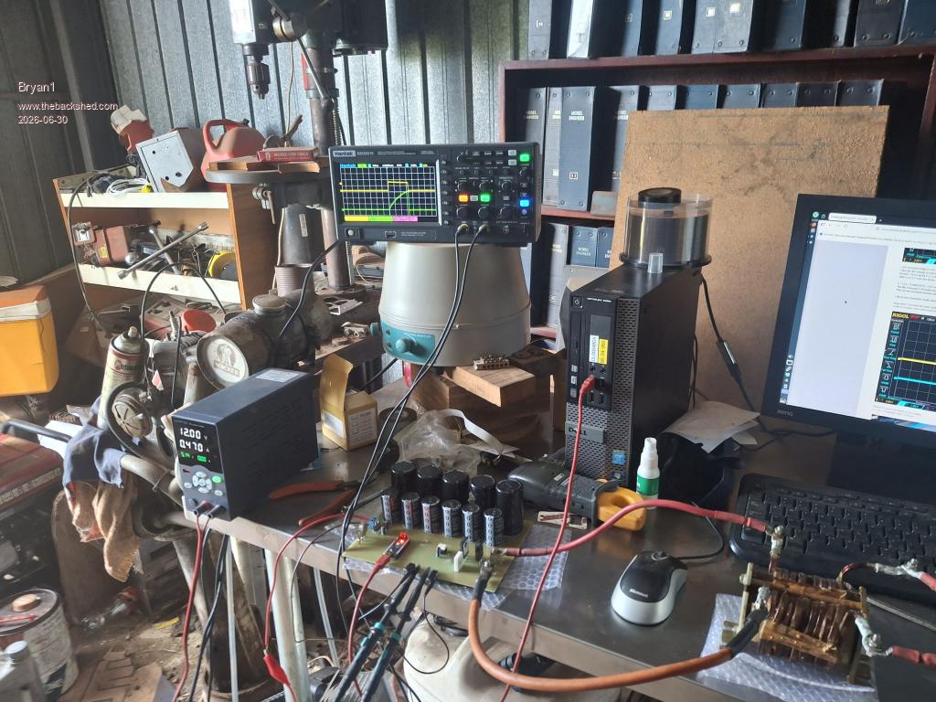
Here is a pic of the setup
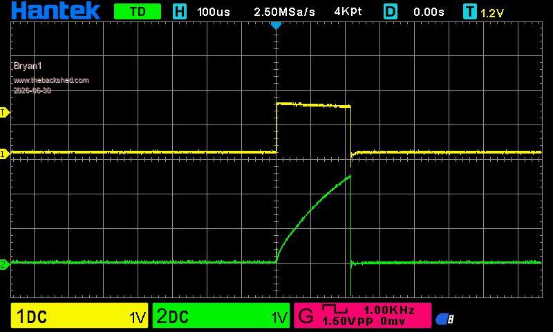
Now this was with a 210us pulse So with a 2.5 voltage rise on the sense 2.5/0.02= 125 amps
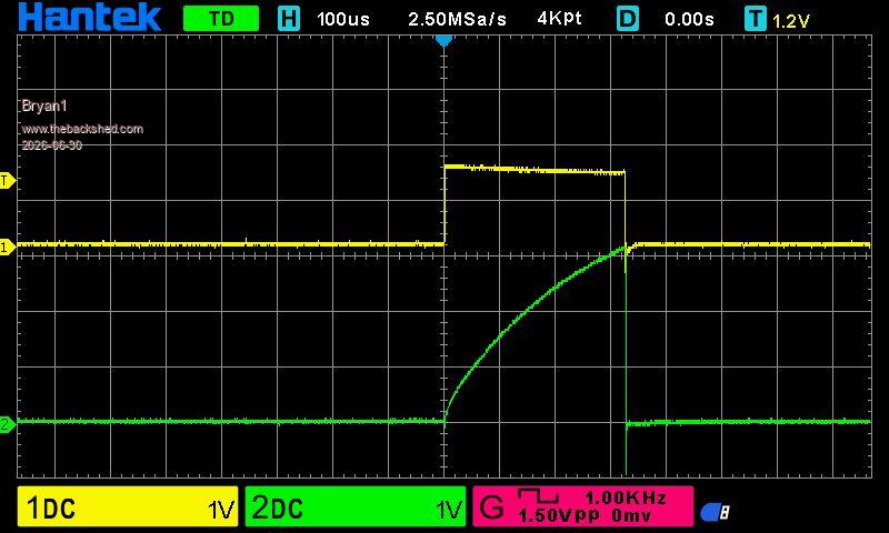
Now a 320us pulse the voltage rise was 3.1 volts so 3.1/0.02 = 155amps
So I pretty happy the tester worked and as I didn't have any TLP250's I used a FOD3182 which just worked.
Now time to test the second choke I made ages ago...
Regards Bryan Edited 2026-06-30 15:18 by Bryan1
Bryan1 Guru Joined: 22/02/2006 Location: AustraliaPosts: 2267
Posted: 05:31am 30 Jun 2026
Copy link to clipboard
Print this post
Had to go into town for some stuff and got thinking with the test on that dual choke not going into saturation mode another test was needed when I got home.
Now I widened the pulse until the sense trace started to falter and found the sweet spot where the sense pulse was stable.
505us Pulse 3.6 volts on the sense trace so 3.6/0.02 = 180 amps
So I do think Tony's old design is still up there with more modern chokes
Regards Bryan
Edit: Now just tried each side and both were the same where around 3 volts (150amps) was the sweet spot before the choke saturated so on a 24 volt system the choke should handle 3.6 Kw which is about the limit for 24 volts. Edited 2026-06-30 15:50 by Bryan1
phil99 Guru Joined: 11/02/2018 Location: AustraliaPosts: 3382
Posted: 06:19am 30 Jun 2026
Copy link to clipboard
Print this post
Look at the pics in Poida's last post. Saturation starts when the trace kicks upward more steeply, not when it rounds off. Do you still have the primary connected? If so the total resistance of the circuit may be what is rounding off the trace, and/or the capacitors running out of charge.
In your last photo the terminals on the right side of the choke should be shorted together to test just the choke.
Bryan1 Guru Joined: 22/02/2006 Location: AustraliaPosts: 2267
Posted: 06:33am 30 Jun 2026
Copy link to clipboard
Print this post
Phill in the first tests the rear 2 connections were connected together so the left connection was to each side of the choke.
Now when I widen the pulse the rounded off trace just kept going higher and no vertical spikes were seen. When the pulse was further widened the trace would drop off and on so I thought that was total saturation.
I now thinking as this is a dual choke if I connected the start of the left to the rear of the right and the same with the other side would this cause a short or would it let me do a test in dual choke mode.
I am good at letting the magic smoke out so until I'm told otherwise this can remain a thought.
In the morning I will switch over to my kipoint inverter so I can take one of the chokes out of my new inverter so I can test the 6 toroid 4 turn configuration.
Now I do have 4 more of these boards so if members want a board just PM me.
Regards Bryan Edited 2026-06-30 16:36 by Bryan1
Page 1 of 2
Print this page
The Back Shed's forum code is written, and hosted, in Australia.

 Notice. New forum software under development. It's going to miss a few functions and look a bit ugly for a while, but I'm working on it full time now as the old forum was too unstable. Couple days, all good. If you notice any issues, please contact me.


 Print this post