
|
|
Forum Index : Electronics : super picaxe logger
| Page 1 of 2 |
|||||
| Author | Message | ||||
| GWatPE Senior Member Joined: 01/09/2006 Location: AustraliaPosts: 2127 |
I have spent a fair bit of time recently with a concept for making an expandable logging system. I now have a modular system that allows small picaxe modules to be connected easily to a central processor that handles the computer connection. I use capacitor coupling of the serial interconnection data transfers, with an opto coupler to synchronize each module. A picaxe 28X2 can be used as the controller, giving 27 separate recording channels of 10bit analogue, or 54 channels of 8bit analogue, or 54 digital inputs, there can be mixed configurations as well. My concept testing project is a battery cell monitoring system for recording the charging and discharging behaviour. I will be looking at real time recording of all measurable components in my house, including solar and wind systems, voltage and current. I will be investigating clamp sensors for measuring AC currents in the house as well. The Velleman recorders I am using at present are only 8bit resolution and 4 channels, with limited range options. They are not passive recorders. Files are only created when the logging is stopped. This is problamatic for long recording times. The large number of inputs with this polled recording system give plenty of recording options. Gordon. become more energy aware |
||||
| GWatPE Senior Member Joined: 01/09/2006 Location: AustraliaPosts: 2127 |
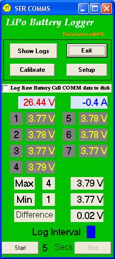
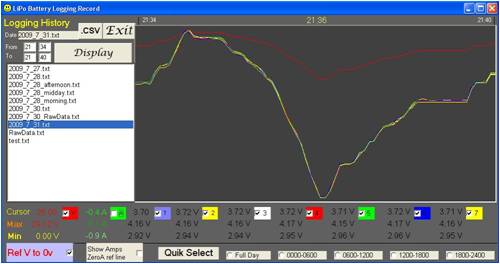
Here are some screen shots of the calibration screen and the main logging window and an example graph. 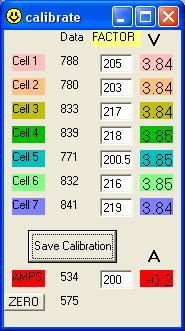
I now have a pretty good handle on VBcoding, and this makes the behind the scenes task a bit easier. To expand the system more than 28 channels will require use of the scratchpad area of the picaxe. My first attempt to use this was not a great success. The X2 chips only have 28 GP word registers, and this limits normal data transfers. May have to look at this a bit more. I was able to simplify the "file to graph" selection window. As long as the files are in a subfolder called logs, and contain valid data, they can be graphed, by just clicking. I have made a small picaxe 08M module that has a programming port. This can be easily added as a daughter module to a bigger project. All that is needed is the opto coupler and some external scaling resistors, or headers for Alegro type current sensors. My picaxe 28X2 is now only a serial data multiplexer with some simple calcs for ensuring valid data, and the data string generator for the computer transfers. I will be looking at a version with a larger dedicated LCD with a logging output option as well. Gordon. become more energy aware |
||||
| Janne Senior Member Joined: 20/06/2008 Location: FinlandPosts: 121 |
Hi Gordon, Just curious, are you using the hardware serial pins in the axe 28x2? If so, how high baudrates you have obtained? If at first you don't succeed, try again. My projects |
||||
| GWatPE Senior Member Joined: 01/09/2006 Location: AustraliaPosts: 2127 |
Hi Janne, I have not had much success with the default comm settings with the picaxe serial comm pins. I have resorted to using serin and serout commands, with N2400 configuration, with individual data identification strings embedded in the comm string. This has produced the highest reliability of the comm transfers. Basically the slave units go about their business of reading the analogue inputs and sending the data packets to the comm output. If the synch pin is enabled, then the same packets are re-sent as the data was not recieved without checksum errors. As soon as the checksum is verified, then the control program moves to look for the next slaves data. There are 9 controlled output pins, so there could be 9 slave units sending serial data to the 9 input pins of the 28X2. Here is an example of code for a picaxe 08M slave unit. #picaxe08m main: readadc10 1,w0 w1=w1+w0 w1=w1/2 readadc10 2,w0 w2=w2+w0 w2=w2/2 readadc10 4,w0 w4=w4+w0 w4=w4/2 w3=w1+w2+w4 repeat: serout 0, N2400, ("A",#w1) serout 0, N2400, ("B",#w2) serout 0, N2400, ("C",#w4) serout 0, N2400, ("K",#w3) if pin3=1 then repeat goto main end Here is example code in the picaxe 28X2. #picaxe28x2 adcsetup =4 main: ' hold slave unit#1 ON until data is all read in high 11 one: serin [100,one],B.3,N2400,("A"),#w10 serin [100,one],B.3,N2400,("B"),#w11 serin [100,one],B.3,N2400,("C"),#w12 serin [100,one],B.3,N2400,("K"),#w13 'calculate and compare checksum w0=w10+w11+w12 if w0=w13 then w2=w2+w12 w2=w2/2 w3=w3+w11 w3=w3/2 w4=w4+w10 w4=w4/2 ' serout 20,N2400,("[cell2-4 read OK]") low 11 else 'continue trying to read same serial data again goto one endif ' hold slave unit#2 ON untl data all read in high 8 two: serin [100,two],B.1,N2400,("D"),#w10 serin [100,two],B.1,N2400,("E"),#w11 serin [100,two],B.1,N2400,("F"),#w12 serin [100,two],B.1,N2400,("L"),#w13 'calculate and compare checksum w0=w10+w11+w12 if w0=w13 then w5=w5+w12 w5=w5/2 w6=w6+w11 w6=w6/2 w7=w7+w10 w7=w7/2 ' serout 20,N2400,("[cell5-7 read OK]") low 8 else 'continue trying to read same serial data again goto two endif 'read cell number one manually readadc10 A.0,w9 w1=w1+w9 w1=w1/2 'read pack current manually readadc10 A.1,w9 w8=w8+w9 w8=w8/2 w9=w1+w2+w3+w4+w5+w6+w7+w8 serout 20,N2400,("[A",#w1,"B",#w2,"C",#w3,"D",#w4,"E",#w5,"F",#w6,"G",#w7,"H",#w8,"I",#w9,"Z]") 'indicate a successful data transfer low B.7 toggle B.7 pause 200 toggle B.7 goto main end The system gives 2 cycles of readings per second to the logging computer. This is OK, as the data is logged only every 5 seconds. I have a log RAW data button for checking the computer COMMS if needed. I am still working on a generic type logging system, with a selectable input system to allow any sensor to be connected to any input, and the choice made with a button for either input offset correction or not. This will be like all the calibration settings will have a zero button and a calibration factor. The window will be quite a bit larger and the VBcoding more complicated. May have to restrict the logging interval a bit. Gordon. become more energy aware |
||||
| GWatPE Senior Member Joined: 01/09/2006 Location: AustraliaPosts: 2127 |
The internal data storage limit of the picaxe28X2 upon further digging seems to be about 1500bytes. This equates to about 750 channels of 10bit analogue data. The maximum efficiency of components would be as multiples of 4 dedicated picaxe08M slave units sending data to picaxe14M's, this would give 12 channels. 9 of these could be multiplexed into a picaxe28X2 for collating to the computer logger. This gives 108 channels in the simplest form, using 36 picaxe08M and 9 picaxe14M and 1 picaxe28X2. I have an upcoming application requiring 45 channels in an EV battery, so I a configuration could be, 15 picaxe08M slaves as the primary ADC. The units would be powered from a 12V AUX battery. There will need to be 14 isolated 5V supplies fed from a 12V-5V converter. There would be 4 picaxe14M units receiving this data and then re-transmitting to a picaxe28X2. The picaxe28X2 will handle the number crunching and LCD output display. There is opportunity to record other parameters and have some user interaction switches for trip resets etc. Some status leds would be useful to display events that may have been missed on the LCD display. Max & Min pack volts for trip charge/discharge cycle, and max & min voltage during service would be useful. Will still need to see if the cycle read time will be short enough for the application to be useful. The high voltages involved will present some issues as well. This will be a fairly daunting project. Gordon. PS: The data storage uses the scratchpad in the picaxe28X2, and the @ptr and @ptrinc functions. I may require the storage register acccess in the picaxe14M as well, with peek and poke functions. become more energy aware |
||||
ums39 Newbie Joined: 05/10/2009 Location: TurkmenistanPosts: 1 |
hello all , you are all doing great things i m very proud of finding this site |
||||
Downwind Guru Joined: 09/09/2009 Location: AustraliaPosts: 2333 |
Hi Gordon, Have you considered using I2C for data transfer between master and slaves. I2C is a great system and only requires 2 pins on the master to talk to ALL the slaves, as each slave has its own address. All slaves and any other I2c device (like a real time clock, lcd display, Eeprom, etc) all hang off a common bus line of SCL & SDA plus 5v+ and Neg. An 18X can then be used as a master leaving 6 outputs and 5 inputs free for other uses if needed. Any large data storage could be stored in a Eeprom also on the I2C bus, so as to greatly expand the memory capacity. Pete. Sometimes it just works |
||||
| GWatPE Senior Member Joined: 01/09/2006 Location: AustraliaPosts: 2127 |
Hi Pete, The major problem with individual cell measurement is the changing relative gnd of each cell voltage. I2C is a COMM system and not a measurement system. The problems still exists with the measurements. There would be increased complexity in the COMMs management[software overhead]. I have had current system working now for 6 weeks on a 7 cell battery. Only another 46 weeks to go in the testing. I may be looking at a Dallas fob key system that uses I2C COMMS as a start. Gordon. become more energy aware |
||||
| Downwind Guru Joined: 09/09/2009 Location: AustraliaPosts: 2333 |
Hi Gordon, I don�t see what the problem with measuring cells has to do with I2C. All measurements would be done by the slave(s) and the data stored by the slave until the master addresses the slave and interrogates it. The data would be passed to the master via I2C. The slave would continue to collect data, while the master can process the information from the slave and do as you wish with it. You can have multiple slaves doing all sorts of tasks and one master controlling them all via I2C. Do you have a schematic of what you have now. If you don�t wish to post it publicly and would like to discuss this further, ask Glenn for my email address. I am happy to help if able. Pete. (Downwind) Sometimes it just works |
||||
| GWatPE Senior Member Joined: 01/09/2006 Location: AustraliaPosts: 2127 |
Hi Pete, I don't use schematics. I go straight to the PCB. I have a modular approach and have a stock of 08M componentry that I am working with. My systems are working well. here is a link to some graphed data from the 7channel LiPo battery cell monitoring system. Gordon. PS The various ADC inputs in my arrangement make the need for connections without a common ground on the individual microprocessors. I2C would require opto coupling of handshake and data lines. become more energy aware |
||||
| Downwind Guru Joined: 09/09/2009 Location: AustraliaPosts: 2333 |
Hi Gordon I often do the same and go straight to PCB and if needed then do the schematic after. I am curious of how you are reading the cell voltage. I mean with what hardware config. I know via adc but with what components and how. The 08m is a good little chip but no I2c so the idea of using a I2C bus wont work with the 08M. How many 08m"s do you use to monitor all the cells. You have got me wondering on how this all works as i cant get a mental picture to the information given. Pete. 
Sometimes it just works |
||||
| vasi Guru Joined: 23/03/2007 Location: RomaniaPosts: 1697 |
Hints or brain storming: Serial comm. and string formatting. Master commanding his slaves... etc... Look also at Glenn;s Windmill Logger with 08M for some of hardware details... Of course, you can do your own I2C implementation but is much costly. Look at Firmata for principles or at UBW firmware for 18F2550 with much speed on USB comm. ----------- Don't expect schematic or firmware. If Gordon delivered his system sealed, then he want to protect his work. Hobbit name: Togo Toadfoot of Frogmorton Elvish name: Mablung Miriel Beyound Arduino Lang |
||||
| GWatPE Senior Member Joined: 01/09/2006 Location: AustraliaPosts: 2127 |
Hi Pete, The picaxe08M has 3 10bitADC channels. I use all channels on 2 08M's. one 08M has a gnd reference at the positive of cell1. the other 08M has a gnd reference at the positive of cell4. The idea is to have the lowest possible gain resistors in the cell voltage measurement for each channel. The 08M are each operating from a 5V isolated regulated supply. The controlling IC is a 28SX2. This is overkill at the moment, as I could use an 08M. The battery current and the lowest cell voltage are measured on this 3rd micro. The control IC polls each 08M and requests a data packet. The data is continually measured and averaged with the previous data, before being transmitted. I use a serin function with a validation string to control data flow. I had no luck with opto couplers, so resorted to caps. At the completion of a read cycle, the data is transmitted serially to the PC after checksums and data validation was passed. For a 45cell battery pack, there would be 16 micro's. If the micro's had 16bitADC, the task would be simpler, as all measurements could be made from a common gnd. I chose to keep the system modular to reduce the potential problems with busbar cell interlinks introducing measurement errors. The system has to work reliably down to 10mV sensing. A 10bit resolution is 1 in 1000, so with a 5V rail you end up with approx 5mV per ADC step. I hope this helps. Gordon. become more energy aware |
||||
| GWatPE Senior Member Joined: 01/09/2006 Location: AustraliaPosts: 2127 |
I have no time to produce complex schematics. I had trouble enough making simple layouts for my capacitor voltage multipliers, that seem to have a lot of readers stumped. I have already supplied firmware coding. As it turns out the significant contribution I have made is the capacitor multipliers and the loading benefits they offer to a windmill alternator system. This has been provided publically on this forum, so individuals can benefit. I won't profit from this, but many will benefit. The electronics I dabble in would become a side issue if I spent the time needed to document so others could follow. I am not a good draughtsperson and my writing is not that good either. I can only do so much on a keyboard. Some of my ideas will become commercialy available. The 4um and my windmills eat into my surfing time too much as it is. Gordon. become more energy aware |
||||
| vasi Guru Joined: 23/03/2007 Location: RomaniaPosts: 1697 |
Hi Gordon, was not a criticism or irony (Your work is your work and you can do whatever you want - I have seen images from Trev and not the post with slave firmware so I thought is a commercial product). Sorry for trouble. Vasi Hobbit name: Togo Toadfoot of Frogmorton Elvish name: Mablung Miriel Beyound Arduino Lang |
||||
| Downwind Guru Joined: 09/09/2009 Location: AustraliaPosts: 2333 |
Gordon Thanks for the circuit description, that explains a lot. I do understand the time it takes to document a project and thankyou for your time given. If this is a circuit you would like to post in a schematic, and you can draw a rough layout on paper using any symbols you like and photograph the drawing. I could put it into a software drawn schematic that you could post or print if you want the circuit to be known. Just email the photo. Same for your capacitor circuit to, as i am yet to get it straight as well. I got lost in the debut with revised drawings etc. to what was right or wrong. Be good to have a short article just on your cap findings and with a clear schematic. (time??) I know how hard it can be to write and draw when the hand dont do what the mind thinks. (Thats why i use software) Its always interesting to see what others do in their circuits and the bits we learn, and use in another task. Keep up the good work. Pete. Sometimes it just works |
||||
| GWatPE Senior Member Joined: 01/09/2006 Location: AustraliaPosts: 2127 |
Hi vasi, Trev posted some images of my cell equalizers. The logging is to monitor performance of the equalizer. The logging project for the battery cell behaviour during charging and discharging is to document what happens to LiPo batteries during these typical situations. I know that commercial display systems exist, but I needed to record as well, and my budget is minimal. A final systerm will be a black box that may be used as part of an EV or RE installation. Battery manufacturers should be interested as problems with warranty claims could be objectively verified. Hi Pete, I will see how things pan out. This project may just be a 1 off. The cap cct should be taken as it just works this way. Someone with a good spice software modelling background should be able to model the cct and confirm my testing. I presume spice can handle caps and diodes interaction with a varying AC source. The engineering bods would be the best to do this side of things. Gizmo has plans for an article on the cap multipliers. Gordon. become more energy aware |
||||
| GWatPE Senior Member Joined: 01/09/2006 Location: AustraliaPosts: 2127 |
I have been working on multi channel data loggers for some time now. The super picaxe logger works well, but new isolated amplifiers are available now that open up other options. One of the biggest problems with a micro ADC data logging input is the single reference for the on board ADC's. The picaxe 28X2 is a good choice for data logging ADC with a large number, "9" ADC's in a single package, without having to go to a 40 pin package. I now have some optically isolated linear amplifiers. 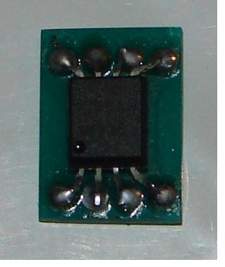
This is one. They are SMD devices, so this one I have soldered to a small pcb for testing. The part number is ACPL-C784-0D0E. These are an 8pin device. + & - 5V with differential inputs, with optically coupled output. I have also been able to configure normal opto couplers to give a linear voltage transfer. These require a gain and offset calibration, but at least the transfer function is linear. I will be able to have isolated measurement of voltage, with the outputs able to be referenced to the micro ADC directly. The use of these components will increase the resolution. I hope to achieve 2-3mV resolution for voltage, and 50mA resolution for current on my LiPo battery test rig. The current measurement will require an isolated 5V power supply, but voltage will need <1mA from the voltage source being measured. I intend to reduce the loggers from 5 to 3, by combining functions. This will simplify the applications needed to control the data storage. I am intending to keep my LiPo testing separate, and monitor all windmill components on a single logger. The 240V stuff is still separate, and can backup some windmill and LiPo battery logging. All up, the logging will record these aspects System 1 WINDMILLS & solar RE:- PICAXE 28X2 24V battery system voltage windmill 1 output voltage pre elect booster windmill 1 output current pre elect booster windmill 1 24V battery current post elect booster windmill 2 24V battery current post cap booster solar panel 24V battery current post solar MPPT. Includes an additional windmill 2 component from 48V system. 48V battery system voltage windmill 2 voltage pre cap boost windmill 2 rpm windmill2 48V battery current System 2 LiPo battery PICAXE 28X2 8 cells individual voltages pack current System 3 CC128 house monitoring Total RE production Total J consumption to compare with utility meter Total house M consumption Windmill production LiPo battery Inverter consumption LiPo battery recharge consumption Net instantanous Import/Export Instantanous M consumption to compare with utility meter Instantanous Export to compare with utility meter Total house M consumption J hot water consumption Outside temperature Individual kWhr are calculated for all house monitoring power data. Additionally, kWhr & Ah are calculated for LiPo battery discharge and recharge. kWh data for all parameters related to the batteries will be calculated. Eventually I intend combining the data sets into a database that can be uploaded to the I-net. A useful point that has surfaced is to separate the logging functions from the viewing functions. The COMM problems are best kept to one computer. The remote access allows almost any computer to see the data. Once the data is in a file, any computer with network access can see the data. The operating system and drivers no longer complicates the process. The data can even be copied to another computer and the viewer that is rum on the other computer can still access the data, even though there are no COMMS. I am running a wireless/wired LAN, and now I can share the data without having to get COMM's working first on the other computer. This aspect becomes more evident when data and ideas are shared with others, who may not have the same computing resources. This is an ongoing process and is probably going to get a revamp should higher resolution ADC's become affordable. Gordon. become more energy aware |
||||
| Downwind Guru Joined: 09/09/2009 Location: AustraliaPosts: 2333 |
Hi Gordon, Sounds like you are progressing nicely. Thats a shhh lot of data you are processing. The only draw back with the optically isolated linear amplifiers is the +5/-5 supply needed. Bit of a bugger if you want to use battery power, otherwise sounds made for the job. I am considered using F88 pic's for adc slaves they would give 6 adc's a slave and add a slave for another 6. They are a cheap chip at $2.00 each and one program can do all the adc slaves. Use a picaxe as a master for its easy programming. Are the optically isolated linear amplifiers avaliable in dip package. Have you got a data sheet for the ACPL-C784-0D0E as was not able to locate one. Pete Sometimes it just works |
||||
| GWatPE Senior Member Joined: 01/09/2006 Location: AustraliaPosts: 2127 |
Hi Pete, the isolated amps are available from Farnell 171-0663. search the online catalogue and there is a link to the datasheet. I am sure there would be a DIP version. The amps only require a single rail. The data sheet sheds some more light. They are primarily designed for current measurements with a low resistance shunt. More versatile than a HALL effect current sensor. I have not fired one up yet. Most of the logging files are now about 1MB/day. I have to look at setting a std XML format for my data. There are not enough letters, so I will need to have some type of coding. I am looking at <V1>,<V2>...... etc for battery volts. <A1>,<A2>.... etc for amps. This will not be easy. Looking too hard already. The problem with all the sensing is the birdsnest of thin wires that results. I have to tidy the main wiring first. The wireless sensing has benefits, but not at the expense of data integrity. I have found that the 10 sec recording interval is good enough to capture most info, without too large a file size. I tried 5 sec, but screen updates and graphing became a bottleneck. 30 sec, and longer integrations are needed and more temporary variables required. I have tried to keep individual data records to a max of 100 characters. The 10000 lines yields the 1MB file size. Binary coding without XML type identifiers would reduce the file length, but at the moment the picaxe only needs to handle an output string of under 100 characters. The logging computer in my case is a PC, so file size is not too critical. I am having a couple of weeks break, so any new testing will have to wait till next year. Hopefully my loggers will continue doing there thing while I am socializing interstate. Won't be checking systems remotely until the router has been reconfigured. Next years priority. Gordon. become more energy aware |
||||
| Page 1 of 2 |
|||||
| The Back Shed's forum code is written, and hosted, in Australia. | © JAQ Software 2026 |
