Notice. New forum software under development. It's going to miss a few functions and look a bit ugly for a while, but I'm working on it full time now as the old forum was too unstable. Couple days, all good. If you notice any issues, please contact me.
kentfielddude Senior Member Joined: 09/05/2019 Location: United StatesPosts: 120
Posted: 03:08am 14 Aug 2026
Copy link to clipboard
Print this post
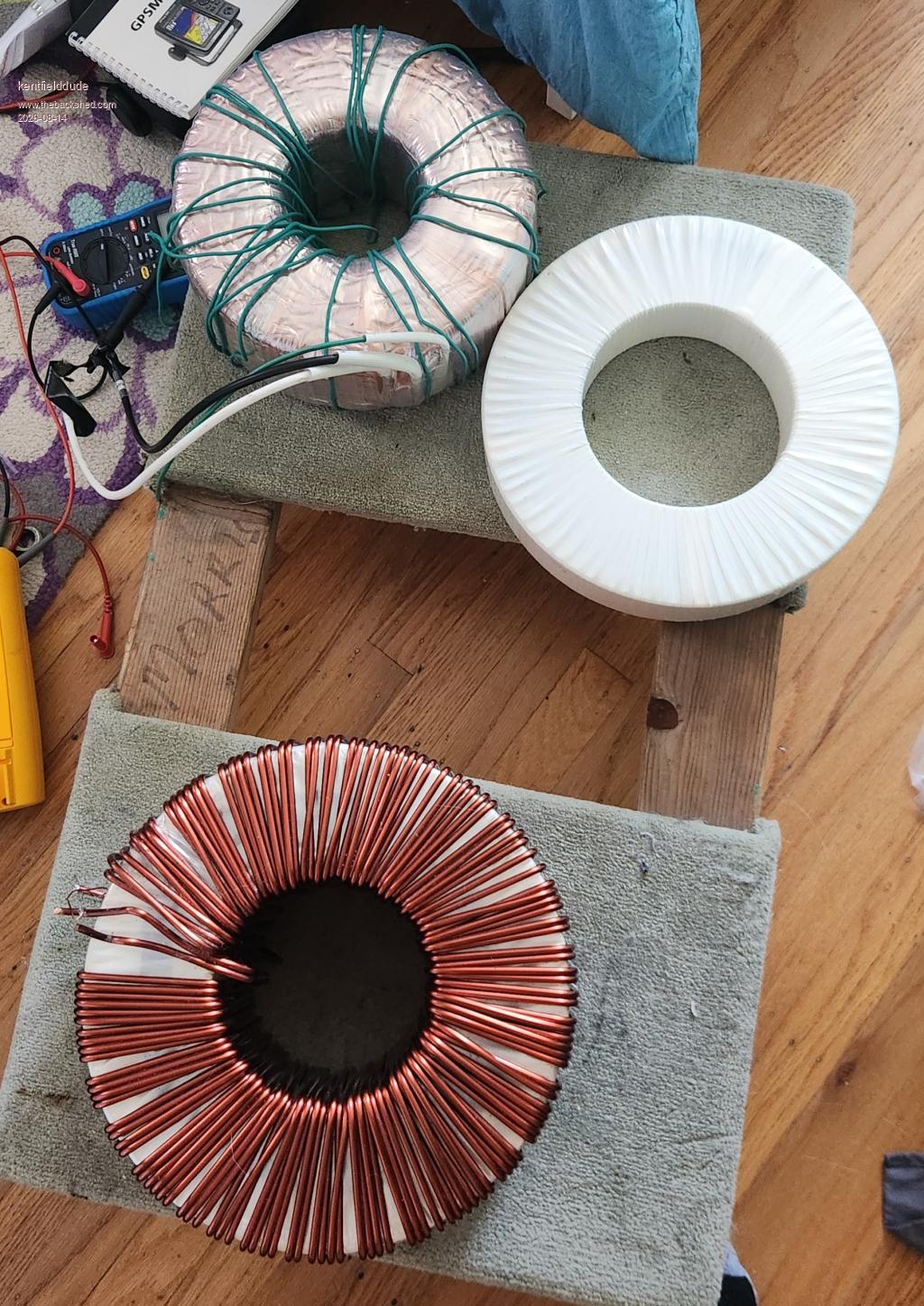
I purchased a toroidal core today. I don't know what it came from but its 46 pounds (21 kg) and I measured it to have a cross sectional area of about 40cm^2. It seems to have a rather large hole relative to its size.
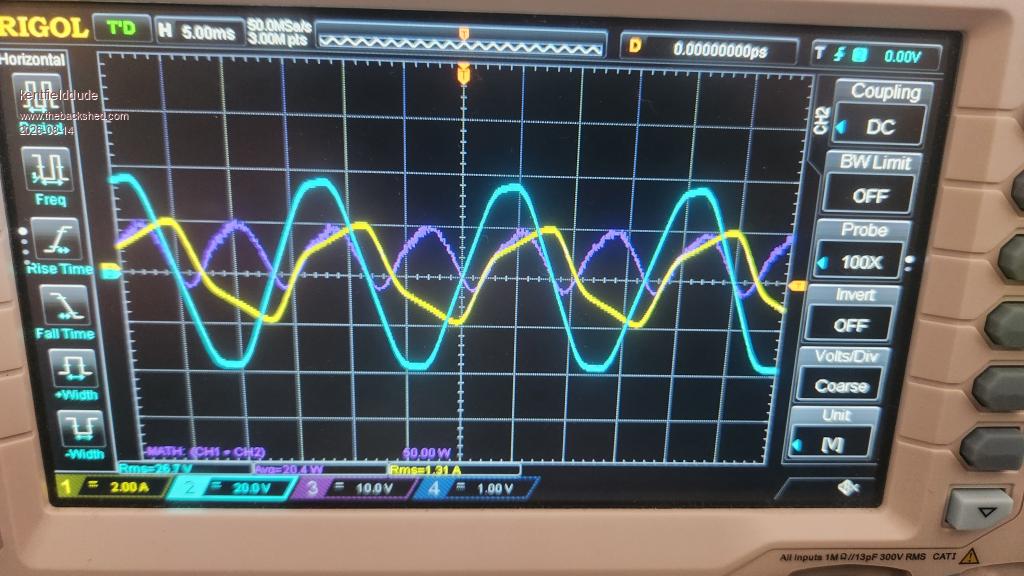
I put 60 turns on the core, and applied different voltages. I used CP2100B current probe and a differential probe on my oscilloscope.
I set a math channel to do A * B, then I took the average of the math channel to get power consumption.
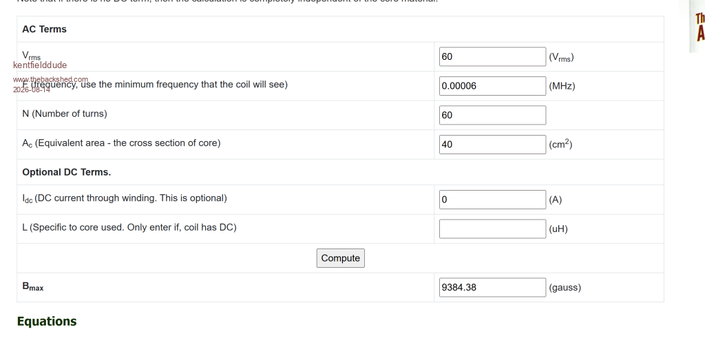
At 60V AC its drawing 91 watts. I plugged 60V ac into the flux calc and i get 0.94 Tesla. Seems like a high idle power. Could it be bad core material or am I doing something wrong here?
kentfielddude Senior Member Joined: 09/05/2019 Location: United StatesPosts: 120
Posted: 04:02am 14 Aug 2026
Copy link to clipboard
Print this post
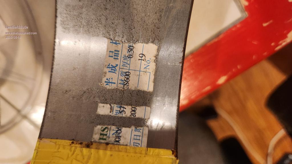
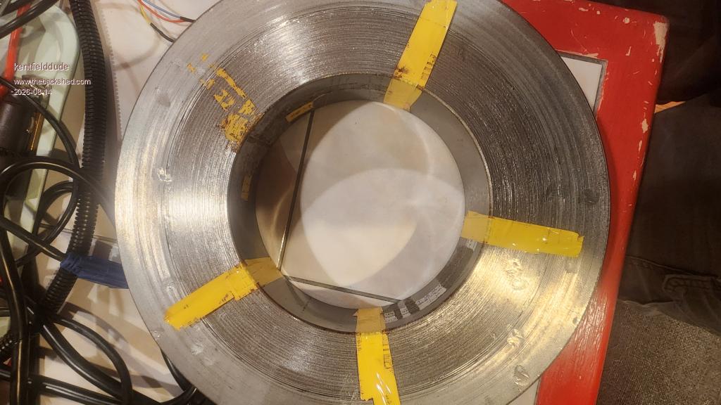
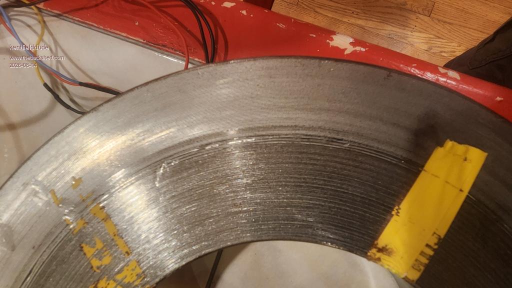
Hmmm. So many damn layers of thick mylar on this core. How do I tell if this is good core material. It looks like tofu steel to me but I'm no expert.
Godoh Guru Joined: 26/09/2020 Location: AustraliaPosts: 709
Posted: 04:22am 14 Aug 2026
Copy link to clipboard
Print this post
Your idle power is way too high,
I am guessing that you are aiming for a 110 volt high volt side
So your turns per volt look about right.
Do you have any idea what the core is designed for?
Pete
Godoh Guru Joined: 26/09/2020 Location: AustraliaPosts: 709
Posted: 04:23am 14 Aug 2026
Copy link to clipboard
Print this post
Also what are the actual dimensions of the core?
kentfielddude Senior Member Joined: 09/05/2019 Location: United StatesPosts: 120
Posted: 04:31am 14 Aug 2026
Copy link to clipboard
Print this post
OD: 11.5 in = 292.1 mm ID: 6 in = 152.4 mm Height: 2.25 in = 57.15 mm
I'm trying to build a warpinverter. I have a #1 and #2 with decent idle power. I don't know what this core was from that I was just testing. I picked it up for $16 so it's not a big deal if it's bad. Looks like it's 0.5mm steel. Also it looks like they ran out of steel have way through and then just added some more and there's a gap. No varnish or anything on the core just bare steel.
Godoh Guru Joined: 26/09/2020 Location: AustraliaPosts: 709
Posted: 06:59am 14 Aug 2026
Copy link to clipboard
Print this post
So my calculations work out that if the core is any good it will be good for 2.6 kva
you would need 126 turns on the high voltage side for 120 volt output
and 14 turns on the low voltage side for 13 volt input ( 24 volt battery)
kentfielddude Senior Member Joined: 09/05/2019 Location: United StatesPosts: 120
Posted: 01:54pm 14 Aug 2026
Copy link to clipboard
Print this post
Thanks. My main core will have 225V secondary #2 will have 75V secondary #3 will have 25V secondary #4 will have 8.33V secondary
The primary will be whatever the lowest voltage my battery will see. Still thinking about if I will run 48v battery or a higher voltage one.
Im going for low idle draw. I was thinking of using this as core #3 but its to big anyways.
Core 1 15k Va Core 2 5k va Core 3 1.67k va Core 4 550 va.
kentfielddude Senior Member Joined: 09/05/2019 Location: United StatesPosts: 120
Posted: 02:05pm 14 Aug 2026
Copy link to clipboard
Print this post
Godoh. My largest core, which you can see in the photo, is 84 cm². I've kept the original primary winding on it. The primary had two 4.6 mm diameter copper wires wound in parallel, with approximately 66 turns on the core. For a 225 V primary, I need around 108 turns, so I put the two windings in series to get 132 turns. With a 4.6 mm diameter wire, the cross-sectional area is about 16 mm². At 4 A/mm², that gives me around 15 kW. Is it okay if the windings that were originally in parallel are now connected in series and wound on top of each other? If there were a short between them, would it cause a sudden drop in the output voltage? I used a megohmmeter to test between the two parallel windings while they were isolated, and I got an open circuit on the 1000 V setting, which is the maximum voltage my meter can test.
johansen Newbie Joined: 01/08/2014 Location: United StatesPosts: 11
Posted: 04:03am 15 Aug 2026
Copy link to clipboard
Print this post
That core is similar to a 65 pound transformer i have from a double conversion ups.
Its rated for 6kw and wound with 8 gauge wire, so it has a 240 primary and a 120 208 240 secondary.
1.4 volts per turn and only 20 watts power draw.
So 164 turns for 240vac.
I think you need a more accurate watt meter Edited 2026-08-15 14:06 by johansen
kentfielddude Senior Member Joined: 09/05/2019 Location: United StatesPosts: 120
Posted: 05:25pm 15 Aug 2026
Copy link to clipboard
Print this post
I'm pretty sure it's just a bad core. My other core has 15w power consumption at 1T flux density. This has 91W consumption at 1T flux density. I also had a kill-a-watt meter hooked up to my variac that was feeding into the core. It was pretty close to what I was getting with the current probe setup. It was a bit higher but it's also including the losses coming from the variac transformer
. Edited 2026-08-16 03:29 by kentfielddude
tinyt Guru Joined: 12/11/2017 Location: United StatesPosts: 564
Posted: 09:39pm 15 Aug 2026
Copy link to clipboard
Print this post
Looks like it is the outer half that has no varnish. Maybe you can ohm out the OD surface and the ID surface to find out. Edited 2026-08-16 07:39 by tinyt
phil99 Guru Joined: 11/02/2018 Location: AustraliaPosts: 3399
Posted: 10:22pm 15 Aug 2026
Copy link to clipboard
Print this post
Yes, lack of insulation between layers would greatly increase the eddy current power loss in the core. The amount of distortion of the I waveform is more than I would expect from GOSS (Grain Orientated Silicon Steel). The wrong steel could increase hysteresis losses.
The scope image shows only a small phase shift between V and I, it should be almost 90°. The purple trace (power) is nearly all above the 0 line showing a lot of power is going into the core but little being returned on the next ¼ cycle. An almost equal amount should be returned.
Probably not practical to unwind it, varnish the surface then rewind it.
Solar Mike Guru Joined: 08/02/2015 Location: New ZealandPosts: 1255
Posted: 05:12am 17 Aug 2026
Copy link to clipboard
Print this post
I have a similar problem with an old variac core, the area is 36 cm^2, winding on 300 odd turns, it draws 0.4 amps as measured on my ac current meter when fed with 50 Hz 230v. Its horrendously inefficient. Thought of placing it in a friends kiln next time they do a firing and bake it for a few hours, then unwind it, stretch between two trees and use fence strainer to keep it tight, de-grease and re-varnish, then wind it back up on a former.
Mike
phil99 Guru Joined: 11/02/2018 Location: AustraliaPosts: 3399
Posted: 06:15am 17 Aug 2026
Copy link to clipboard
Print this post
Variac cores are usually decent quality GOSS with an oxide or varnish coating. The usual reason for high idle current (and occasional tripping of the CB at switch-on) is the flux density is too high. Adding more turns should help. Be careful with the temperature and time, check the metallurgy specs for the annealing temperature** and time for GOSS. Up to the "normalizing" temperature is ok but at the annealing temperature the grain structure will be ruined and you will be left with ordinary silicon steel, needing many more turns and getting a lower maximum power rating.
** Foundries and metal fabricators call any heat treatment "annealing" but this really annoyed the metallurgist at one place I worked. Normalizing relieves internal stresses in the metal without changing the crystal structure but genuine annealing can change it completely. Edited 2026-08-17 16:23 by phil99
Solar Mike Guru Joined: 08/02/2015 Location: New ZealandPosts: 1255
Posted: 08:40am 17 Aug 2026
Copy link to clipboard
Print this post
50 year old core made in the USA, who knows what quality steel is in it, manufacturing Co. in NZ makes these types of cores, will contact them see what temperature to aim for.
kentfielddude Senior Member Joined: 09/05/2019 Location: United StatesPosts: 120
Posted: 12:03am 18 Aug 2026
Copy link to clipboard
Print this post
My crappy core has continuity between all the layers
phil99 Guru Joined: 11/02/2018 Location: AustraliaPosts: 3399
Posted: 12:20am 18 Aug 2026
Copy link to clipboard
Print this post
There will always be continuity when measured with a multimeter as it is one long strip of steel. Even if multiple strips have been used the cut edges of adjacent layers often touch in places but this adds little to the loss as the resistance is fairly high, tenths of ohms to several ohms. The problem is when the broad surfaces are in direct contact, the resistance gets down into micro ohms resulting in a large circulating current.
kentfielddude Senior Member Joined: 09/05/2019 Location: United StatesPosts: 120
Posted: 04:19pm 20 Aug 2026
Copy link to clipboard
Print this post
The outside layer to the inside layer measure about 0.6 ohms.
kentfielddude Senior Member Joined: 09/05/2019 Location: United StatesPosts: 120
Posted: 04:20pm 20 Aug 2026
Copy link to clipboard
Print this post
I need to purchase some Mylar. The oz inverter book says you need 600-800 meters for one toroid. That seems like a hell of a lot of Mylar.
tinyt Guru Joined: 12/11/2017 Location: United StatesPosts: 564
Posted: 05:52pm 20 Aug 2026
Copy link to clipboard
Print this post
The meter probe tip penetrates a thin insulating surface coating or there is no insulation at all.
Page 1 of 2
Print this page
The Back Shed's forum code is written, and hosted, in Australia.

 Notice. New forum software under development. It's going to miss a few functions and look a bit ugly for a while, but I'm working on it full time now as the old forum was too unstable. Couple days, all good. If you notice any issues, please contact me.


 Print this post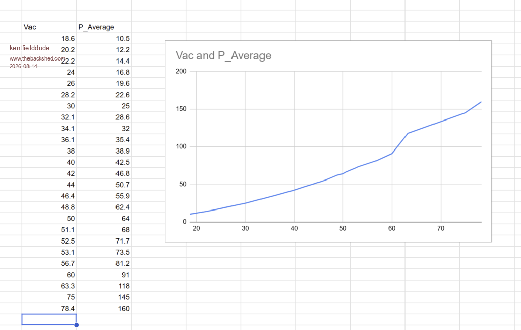
.jpg)