Home
JAQForum Ver 24.01
Log In or Join  
Active Topics
Local Time 04:33 09 Oct 2026 Privacy Policy
Jump to

Notice. New forum software under development. It's going to miss a few functions and look a bit ugly for a while, but I'm working on it full time now as the old forum was too unstable. Couple days, all good. If you notice any issues, please contact me.

Forum Index : Electronics : Na Balancer

Author Message
Dinosaur

Guru

Joined: 12/08/2011
Location: Australia
Posts: 360
Posted: 09:33pm 07 Oct 2026
Copy link to clipboard 
Print this post

Hi All

Long time no posts from me.
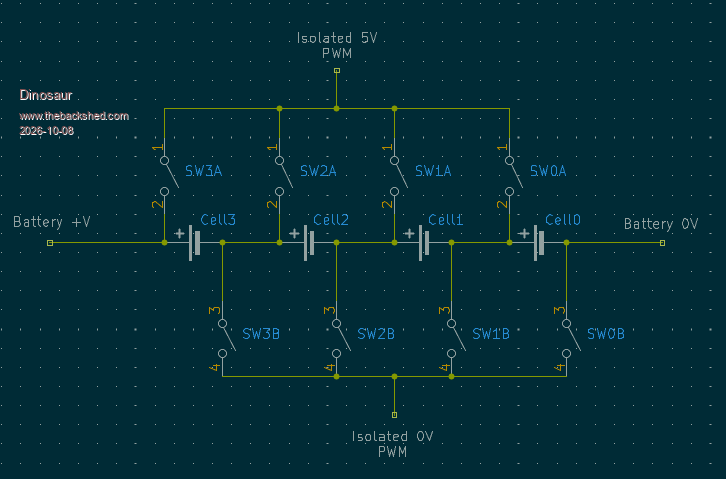
Below a schematic of a Sodium Ion Cell Balancing circuit.
Showing it simplified to get some opinions on a problem.
The switches are all OptoMos Relay modules capable of 20 Chinese Amps.
OptoMos

Maximum I will put through is 5 A PWM at 5v.
The 5v is from an isolated PS, but has not been connected yet, until I am 100% confident.

So perfected the software to measure the Cell voltages and switching the Relays to select the Cell to be balanced.
By switching say SW0A & SW0B together (they are hardwired together) the path of the current from the +5v iso rail connects through to the 0v iso rail.
That is 100% guaranteed correct and problem free.

Been testing with NO iso 5v connected, no load current at all.
When I connected my ESP32-S3 to my laptop, predictably I got some erratic readings from the cells due to powering my ESP32 and ADS1115 from the laptop only.
However, there was never a problem during this period.
Then I decided to use a 240 to 5vdc PS to get a more stable reading and that also worked perfectly. (for about 10 minutes)
I had both Laptop USB and the extra PS connected. There is a schottky diode in between as specified on the ESP32-S3 doc's.
Then for some reason the SW2A started smoking.
The only way to stop it was to disconnect the PS.

I can guarantee that the only Relays being driven were SW0A & SW0B.
There are led's on the 3.3v o/p's.
It took out the ADS1115 as well.
My areas of doubt are;
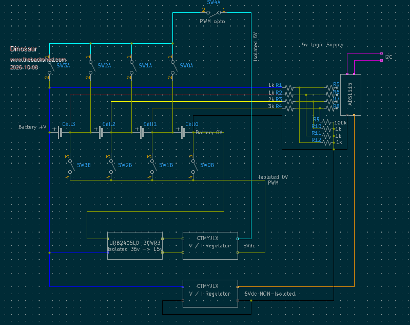
The ADS1115 is connected to the NON-Isolated 5v supply
When balancing Cell 0 the 0V isolated & 0V NON-Isolated are connected.

Would love to hear some opinions on this.


Regards
Hervey Bay Qld.
 
Dinosaur

Guru

Joined: 12/08/2011
Location: Australia
Posts: 360
Posted: 05:07am 08 Oct 2026
Copy link to clipboard 
Print this post

Hi All

A total picture of the system.


Regards
Hervey Bay Qld.
 
FET cemetery
Regular Member

Joined: 17/04/2024
Location: Australia
Posts: 75
Posted: 05:50am 08 Oct 2026
Copy link to clipboard 
Print this post

Way down the bottom of the Aliexpress link it says not for PWM control, on / off only. The 1.5ms turn on time and 1ms turn off would be problematic anyway for anything other than very low PWM speeds.

Edit - ignore me, you're just using the relay modules to connect the 5V PWM, not PWM'ing the modules themselves if I'm seeing it correctly.
Edited 2026-10-08 15:55 by FET cemetery
No stone unturned, no FET unburned.
 
Dinosaur

Guru

Joined: 12/08/2011
Location: Australia
Posts: 360
Posted: 06:04am 08 Oct 2026
Copy link to clipboard 
Print this post

Hi All

Yes I was aware of that, but when testing them at 120Hz, they behaved without any problems.It was a nice square wave. I also have a 10mSec delay between cells when I change cells.
Regards
Hervey Bay Qld.
 
Print this page


To reply to this topic, you need to log in.

The Back Shed's forum code is written, and hosted, in Australia.
© JAQ Software 2026