| Author |
Message |
niall1

Senior Member

Joined: 20/11/2008
Location: IrelandPosts: 331 |
| Posted: 03:34pm 11 Aug 2009 |
 Copy link to clipboard Copy link to clipboard |
 Print this post |
|
hi all
i,m trying to build something that,l regulate high dc (60-80 v) down to about 30v at maybe 60ma...an emitter follower seems to be an ideal solution but no success......transistors are painfully vague to me
this worked at first but then the tip transistor just shorted out all three pins ...didnt even get a chance to smoke
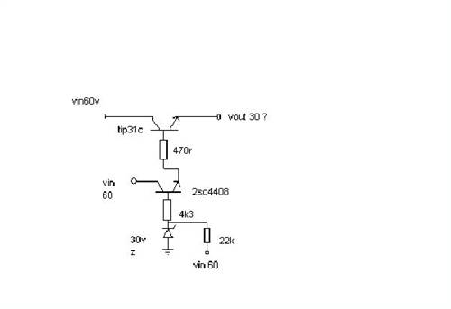
i like to know whats wrong with it as apposed to just tinkering with it ...any help is very welcome
Edited by niall1 2009-08-13
niall |
| |
davef
Guru

Joined: 14/05/2006
Location: New ZealandPosts: 499 |
| Posted: 09:57am 12 Aug 2009 |
Copy link to clipboard |
Print this post |
|
Some minor issues, for robust circuit design (B-E leakage current reduction), but not the cause of blowing the TIP31C up.
Maybe, a high value resistor on the output to ground (10-100K) so that you don't get any reverse bias on the TIP31C b-e junction. IE, if somehow the emitter floats up more than 5 or so Volts higher than the base it will blow (Vebo rating).
Voltage ratings on the TIP31C look more than adequate.
Also, there is no current limiting. There is a fairly simple method of a series resistor on the output with a small transistor across it that will pull the base voltage on the 2SC4408 down when a certain current level is exceeded.
How did it work at first? 30 Volts on the output? For how long? |
| |
oztules

Guru
Joined: 26/07/2007
Location: AustraliaPosts: 1686 |
| Posted: 11:06am 12 Aug 2009 |
Copy link to clipboard |
Print this post |
|
I dont know... haven't built them like that. Feels unstable as it has high impedance on the base.... maybe a load resistor to ground on the emitters of the tip and the 2sc... but..
If you just want one to work well, then this one will give you 120ma@30v from 60v A 2sq inch heat sink will be about 30degC above ambient temp. Rough and ready, I use it for relay coil drivers and rough voltage stage changes.
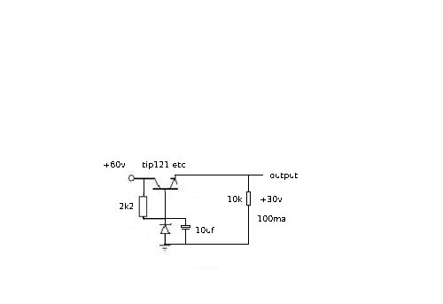
Not what you asked for, but may be what you need.
........oztules
Village idiot...or... just another hack out of his depth |
| |
niall1
Senior Member
Joined: 20/11/2008
Location: IrelandPosts: 331 |
| Posted: 02:08pm 12 Aug 2009 |
Copy link to clipboard |
Print this post |
|
i went back to the circuit again ..i dont have another tip31 (yet)...just some bd241a,s (darlingtons)...i stuck one in anyway plus the suggested resistors
i got it to work dropping 70v down to 30 and nothings beginning to smell ...but i know i,m way of the mark...i,ll try oz,s circuit next
dave the first circuit seemed ok on the bench supply ...it only gave up when i moved it to the mill supply ..
i was a bit fingers and thumbs doing this as well ...
i,ll read up on the current limiting you suggested Edited by niall1 2009-08-14
niall |
| |
oztules
Guru
Joined: 26/07/2007
Location: AustraliaPosts: 1686 |
| Posted: 10:13pm 12 Aug 2009 |
Copy link to clipboard |
Print this post |
|
Looks like someones building a rpm sensor for their mill using a hall effect gear tooth sensor... where are you going to place it?
If it runs on the Mill's AC output, is there a chance of inductive spike getting to it (from maybe pulse switching of the dump load etc??? just a thought)
I don't know where the big cap comes into it, but if it is as big as it looks, it may give high surge (read short) on startup through the darlington if it is on the 30v side of the switch.
I have run out of ideas 
.........oztules
Village idiot...or... just another hack out of his depth |
| |
GWatPE
Senior Member
Joined: 01/09/2006
Location: AustraliaPosts: 2127 |
| Posted: 06:34am 13 Aug 2009 |
Copy link to clipboard |
Print this post |
|
Hi niall1,
I have used ccts very similar to oztules, that is similar to your cct as a pre regulator as well. A single transistor is usually good enough. Some current limiting is usually needed on an uncertain loading, as overload usually results in the reg failing with a shorted transistor with the frying of any sensitive loads.
Gordon.
become more energy aware |
| |
niall1
Senior Member
Joined: 20/11/2008
Location: IrelandPosts: 331 |
| Posted: 11:59am 13 Aug 2009 |
Copy link to clipboard |
Print this post |
|
thats a cunning plan oz ...
but the sensor will have a more mundain function...(if it works)
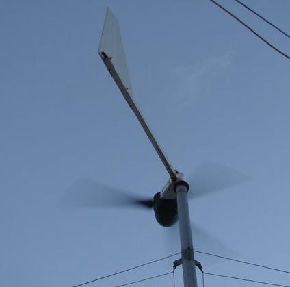
for now i,m saddled with a machine that has no tail and a very thin grasp on what its supposed to be doing in low wind..i,ll try to put a small wind vane upwind of the mill with a sensor either side (more like a trim tab than a vane) and hopefully send the right/left senses back to the ground with...erm...this
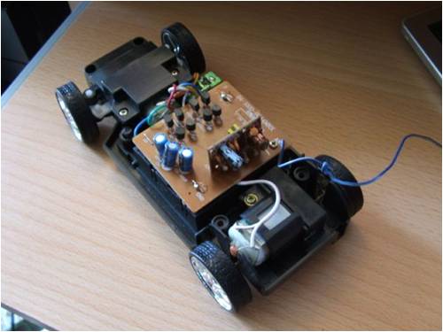
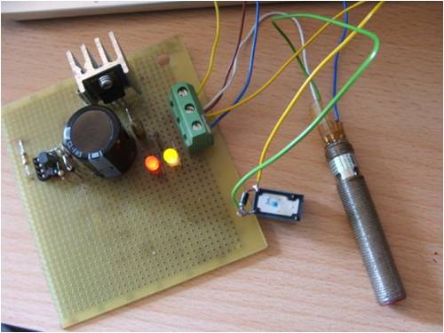
the subarau.....  .......has a very nice 3 channel rc transmitter, years ago this stuff would cost an arm and a leg ...now its just a disposable item (the receiver is the small upright pcb) .......has a very nice 3 channel rc transmitter, years ago this stuff would cost an arm and a leg ...now its just a disposable item (the receiver is the small upright pcb)
and yes i did play with it before i took it apart...
ps ..i,ll take out the cap ...i had no idea it could be an issue... it is on the 30v side ,(should have been in the diagram....)
Gordon as for protecting the load i need to learn a lot more about current limiting ..i do have some tvs diodes and low ma fuses which might be better than nothing if the transistor shorts high ...
i will try to to power it from ac at the mill ..
i was thinking of tapping off one phase and neutral..
(the star point is outside) is there any way to lower the risk of spikes ? Edited by niall1 2009-08-15
niall |
| |
GWatPE
Senior Member
Joined: 01/09/2006
Location: AustraliaPosts: 2127 |
| Posted: 12:48pm 13 Aug 2009 |
Copy link to clipboard |
Print this post |
|
Hi niall1,
I have a very small remote controlled car. The size of a matchbox. You can race around the kitchen table with it.
BTW as it happens, the most expensive transistor will usually fail, to protect the fuse from blowing.
look for foldback current limiting with regulated power supplies.
Gordon.
become more energy aware |
| |
niall1
Senior Member
Joined: 20/11/2008
Location: IrelandPosts: 331 |
| Posted: 08:07pm 19 Aug 2009 |
Copy link to clipboard |
Print this post |
|
i tried to read up a little about current limiting and added in Daves suggestion of the single transistor- resistor on the o/p
the values arnt right , but it,s working (i dont have many low r resistors...) i like the way it trys to work with the power transistor ..now i can short the o/p and it clamps to about 150ma ...before it would go off the scale ... ......seems a lot more passive now
trimming it down to one transistor (oz circuit) with maybe current limiting might be possible then ... (if i can i,d like to protect the sensors)
had giving up on this months ago ......many thanks for the pointers ....... Edited by niall1 2009-08-21
niall |
| |
