| |
Page 1 of 2   |
| Author |
Message |
KarlJ

Guru

Joined: 19/05/2008
Location: AustraliaPosts: 1178 |
| Posted: 11:41am 15 Nov 2009 |
 Copy link to clipboard Copy link to clipboard |
 Print this post |
|
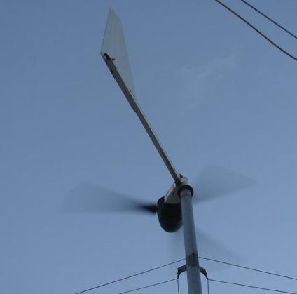
I have one of these
http://www.winddatalogger.com/wind2/
It needs 7-30 V and draws upto 20mA. (says 0.35W peak consumption and 0.16 idling)
I would like to run it off the 48V battery bank.
Will a simple resistor do the job of dropping it down to say 20V?
Also any ideas on a reed switch, hall effect sensor or photo interruptor I can rig up to measure
RPM of the turbine?
I'm thinking a little bracket with something bonded to the magnet rotor or back of prop hub.
It will take 3 anemometers so I guess one it would be counting pulses over 60s interval for RPM.
this is the manual for it http://www.winddatalogger.com/wind2/documents/wind2manual.pd f
this one should be real simple for OZtules...
I am learning....slowly
CheersEdited by KarlJ 2009-11-16
Luck favours the well prepared |
| |
Downwind

Guru
Joined: 09/09/2009
Location: AustraliaPosts: 2333 |
| Posted: 01:35pm 15 Nov 2009 |
Copy link to clipboard |
Print this post |
|
The 7 - 30 volt is that for the power supply or is that for monitoring of the battery voltage.
If you just need a voltage below 30 volt to power the unit than i would use a high voltage regulator.
PN# TL-783 will handle up to 125 volt input and 700mA output adjustable down to 1.25 volt.
So would handle 7-30 volt at 20mA fine.
Might be a bit hard to find and if you have trouble let me know as i have a tube of them.
Pete.
Sometimes it just works |
| |
KarlJ
Guru
Joined: 19/05/2008
Location: AustraliaPosts: 1178 |
| Posted: 06:11am 16 Nov 2009 |
Copy link to clipboard |
Print this post |
|
yes the 7-30V is for the power supply to the wind logger
what resistor values would i need?
in the circuit to step it down to that range?
Karl
Luck favours the well prepared |
| |
Downwind
Guru
Joined: 09/09/2009
Location: AustraliaPosts: 2333 |
| Posted: 08:17am 16 Nov 2009 |
Copy link to clipboard |
Print this post |
|
Karl,
I think using a dropper resistor is flaunt with danger and would use a voltage reg to get the voltage down, as i said in an above post.
Also should you wish to supply something else in the future at a lower voltage you already have a voltage lower than 30 volts that a standard voltage reg can handle.
BUT!
If you want to use a resistor than.
60v - 20v = 40v / 0.02 = 2000
Or a 2K resistor for 20 volts at 20mA (from 60 volts)
A standard 1/4 watt 2K resistor should do.
Pete.
Ps. dont blame me if the magic smoke gets out using a resistor!Edited by Downwind 2009-11-17
Sometimes it just works |
| |
GWatPE
Senior Member

Joined: 01/09/2006
Location: AustraliaPosts: 2127 |
| Posted: 08:46am 16 Nov 2009 |
Copy link to clipboard |
Print this post |
|
You should also place some overvoltage protection across the DC input. Use a 24V 1W zener. This is a very expensive item, so best to provide some protection if the current drops OFF and you only use the dropping resistor.
Gordon.
become more energy aware |
| |
KarlJ
Guru
Joined: 19/05/2008
Location: AustraliaPosts: 1178 |
| Posted: 12:10pm 16 Nov 2009 |
Copy link to clipboard |
Print this post |
|
the voltage regulator you advised me of uses resistors to control the output voltage (or so I made of this page10 )
http://pdf1.alldatasheet.com/datasheet-pdf/view/28835/TI/TL7 83.html
so I meant that but if the dropping resistor and the zener diode will do the trick, thats far simpler.
as long as its safe.
I know nothing about zener diodes, take it the stripe goes to the pos feed to the windlogger and the other end to the neg feed of the windlogger.
Feed the turbine / battery grunt to the 1/4W 2K resistor then to the power of the windlogger and i'm in business and its safe and within the limits of the box.
I figure with a range of 7-30V there is a good scope for a rough method like this.
now for the RPM monitoring....any ideas?
Luck favours the well prepared |
| |
GWatPE
Senior Member
Joined: 01/09/2006
Location: AustraliaPosts: 2127 |
| Posted: 12:40pm 16 Nov 2009 |
Copy link to clipboard |
Print this post |
|
Hi Karl,
You have spent some serious money on the logger. Spend a bit more on a properly regulated power supply that is designed for the power supply you are running off, that provides a protected 12V output, with voltage and current limiting. I would opt for an isolated supply, so there is no way a failure in the power supply will result in high voltage getting to the expensive logger.
STD series regs can go short to supply and unless there is a secondary protection, full input voltage can appear on the output.
Gordon.
PS My atom board PC logging system cost under A$300. This can log for years, probably unattended, and has full PC remote network access available for real time data view, and review of data history. This computer consumes only 14W to do its thing.
become more energy aware |
| |
Downwind
Guru
Joined: 09/09/2009
Location: AustraliaPosts: 2333 |
| Posted: 12:51pm 16 Nov 2009 |
Copy link to clipboard |
Print this post |
|
Karl,
Sorry for the misunderstanding on the resistor.
Ok, R1 is shown as 82R this is correct and a 1/4 watt resistor is fine here.
R2 is shown as a trimpot connected as a reostat.
This means the contre leg of the trimpot is connected to one of the outside legs.
The trimpot shown is 0-8K meaning a 10k trimpot will do and allow you to adjust the ouput voltage from 125v down to 1.25v.
It might be a bit hard to set a fine adjustment with a 10k pot but in your case somewhere between 7-30 volts should be easy enough to set.
It would pay to use both caps shown.
I think i paid about $2.00 each per reg.
As for the zener diode.
Still would use this setup as last resort.
A zener diode has a threash hold voltage that they break down at and conduct in reverse.
This means it is placed in the circuit backwards (stripe end to positive)and when the voltage is greater than the rated diode voltage the greater amount is shunted to ground. It must have a resistor to limit the power it shunts to ground or its an instant fuse!!
If you think of a zener as a weir and when the water reaches the top of the weir the excess flows over to ground.
Great device but voltage reg are far better device for controlling voltage.
I can give you a pcb design for v reg if you need.
Pete,
Sometimes it just works |
| |
Downwind
Guru
Joined: 09/09/2009
Location: AustraliaPosts: 2333 |
| Posted: 12:58pm 16 Nov 2009 |
Copy link to clipboard |
Print this post |
|
Gordons right but the TL-738 is a good reg and has thermal shutdown and i have used many without a problem.
As always if you use the right device for the situation than you should be safe.
I would add a small heatsink to the reg but should not be needed for 20mA. They will run warm as normal.
Pete.Edited by Downwind 2009-11-17
Sometimes it just works |
| |
Downwind
Guru
Joined: 09/09/2009
Location: AustraliaPosts: 2333 |
| Posted: 01:18pm 16 Nov 2009 |
Copy link to clipboard |
Print this post |
|
As for rpm? Hmmm how far do you want to go here?
One simple thought would be to use a reed switch as you surgested.
The reed switches used in alarms for windows are encased in a plastic housing and easy to mount.
Jaycar has several types by memory and also a NC/NO style one that i would stay away from for your use.
These ones are controlled by which way the magnet approaches the switch.Your use would cause all crazy thing to happen with the output i would think.
Use a standard NO reed switch.
If you want a hall effect switch than i would look towards one from a car wrecker and get one that is used in the gearbox for the speedo of a car made in the last 10 years. These are well sealed robust units and very little setup most proberly required.
This is another good reason to use the vreg as above. Because i think most of these speedo sensors are 5 volt operation and you will need to add a 7805 vreg to operate the sensor from.
Most important what will your logger handle as a input signal for this application???
Pete.
Sometimes it just works |
| |
KarlJ
Guru
Joined: 19/05/2008
Location: AustraliaPosts: 1178 |
| Posted: 09:07am 17 Nov 2009 |
Copy link to clipboard |
Print this post |
|
cheers on the volt reg.
Will the magnet attached to the rotor drum cause any problems? (ie with generator output).
how do others do RPM monitoring?
Karl
Luck favours the well prepared |
| |
Downwind
Guru
Joined: 09/09/2009
Location: AustraliaPosts: 2333 |
| Posted: 09:43am 17 Nov 2009 |
Copy link to clipboard |
Print this post |
|
I fail to see why rpm can't be generated by the frequency off one phase before the rectifier.
A lot less crap up the mill and less wiring down the mill tower. Then its just a matter of how clever you are with electronics.
The only concern is the effect of all those capacitors on the frequency.
Other wise its just an AC signal with X hertz.
I think Gizmo done somethink on this style and sure many others have too, but as usual the ghosts are not saying.
Maybe a few priamary turns around a toroid of one phase and some secondary windings for a signal.
Dont really know and have not thought it through.
See what other have to say.
Pete.
Sometimes it just works |
| |
KarlJ
Guru
Joined: 19/05/2008
Location: AustraliaPosts: 1178 |
| Posted: 09:46am 17 Nov 2009 |
Copy link to clipboard |
Print this post |
|
I just spoke to Phill and he reckons the caps screw up the frequency monitoring, he uses a reed switch.
For the moment, I think i'll take dad's advice and concentrate on getting the thing in the air!
Karl
Luck favours the well prepared |
| |
Downwind
Guru
Joined: 09/09/2009
Location: AustraliaPosts: 2333 |
| Posted: 09:52am 17 Nov 2009 |
Copy link to clipboard |
Print this post |
|
Sound like good advice and then you can atleast do some R&D with real values and it maybe quicker to redesign a few things as needed than second guess everything in advance.
Sometimes it just works |
| |
GWatPE
Senior Member
Joined: 01/09/2006
Location: AustraliaPosts: 2127 |
| Posted: 10:03am 17 Nov 2009 |
Copy link to clipboard |
Print this post |
|
I measure frequency directly from the AC. I use a cct similar to the simple CCT that Gizmo used. I use a zener across the opto coupler and use some additional filtering. RPM works down to 30rpm, for a 12 magnet rotor. Good enough for me, and works with the caps as well. I have not been too concerned at rpm below 30, as there is no power to record.
Here is a low wind portion of my windmill logging. The RPM is yellow.
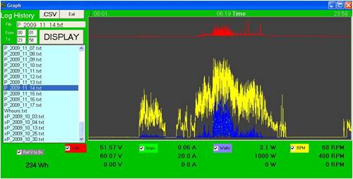
You can see that the blue lines [power] drop out before the rpm.
Gordon.
become more energy aware |
| |
GWatPE
Senior Member
Joined: 01/09/2006
Location: AustraliaPosts: 2127 |
| Posted: 10:07am 17 Nov 2009 |
Copy link to clipboard |
Print this post |
|
Here is a zoom of the first set of peaks above. The 10sec logging interval does not miss too much.
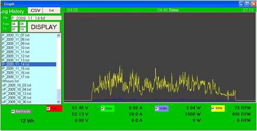
Gordon.
become more energy aware |
| |
Downwind
Guru
Joined: 09/09/2009
Location: AustraliaPosts: 2333 |
| Posted: 09:13am 22 Nov 2009 |
Copy link to clipboard |
Print this post |
|
Karl,
You asked about monitoring rpm and ideas on doing it.
I just remembered there is 3 hall effect sensors on a F&P motor to start with and 1 or all 3 could be used to monitor rpm. Lets face it thats the reason they were there in the first place.
Only draw back is the extra wires up the tower.
I will see if i can find any here and look into it a tad more if you are interested.
Hope you havent trashed the ones you had.
Just a thought.
Pete.
Sometimes it just works |
| |
GWatPE
Senior Member
Joined: 01/09/2006
Location: AustraliaPosts: 2127 |
| Posted: 10:45am 22 Nov 2009 |
Copy link to clipboard |
Print this post |
|
Hi Karl,
If you can't get the cct in Gizmo's article, to work on your mill, I will look into posting my mods that work from the AC output if you like.
Gordon.
become more energy aware |
| |
VK4AYQ
Guru
Joined: 02/12/2009
Location: AustraliaPosts: 2539 |
| Posted: 02:29pm 18 Dec 2009 |
Copy link to clipboard |
Print this post |
|
Hi Karl
I use button magnets stuck to rotor and a small coit 25 turns on a 3/8 ferrite rod 1mm from magnets, old radio antenna off vintage transistor set. Very agriciltural but 100% reliable. use as many magnets as you need, I use 10 as that gives me 10 pulses per rev, easy to work with use a small sigmal diode to get pulse defined, Ebay has small frequency counters cheeep if you want direct readout, for storage and logging we need the project from Pete.
All the best
Bob
Foolin Around |
| |
Downwind
Guru
Joined: 09/09/2009
Location: AustraliaPosts: 2333 |
| Posted: 04:03pm 18 Dec 2009 |
Copy link to clipboard |
Print this post |
|
Hi Bob,
What generator are you using?
If its a F&P hub than why not read the hub magnets.
This was done in the F&P washing machines.(using hall effect sensors)
I do like your sensor approach though.
I have done similar and used the coil out of a relay.
If your sensor was to be fed into a micro than it would need the signal to be under 5v.
Do you have any filtering to clip the signal spike to 5v max. As a coil can generate a rather high voltage spike.
A poor mans scope is a neon globe as used for 240v ac appliance indicator lights, like the globe in your kettle.
It takes about 80+ volts to fire a neon and you can fire one from a magnet passing a coil. This is dependent of the magnet strength and the amount of windings on the coil.
Doubt if button magnets and 25 turns will get this high but can be greater than 5V max.
Its enough to kill an input of a micro if not controlled.
Pete.
Sometimes it just works |
| |
| |
Page 1 of 2 |
