| |
  Page 2 of 2 Page 2 of 2 |
| Author |
Message |
VK4AYQ
Guru

Joined: 02/12/2009
Location: AustraliaPosts: 2539 |
| Posted: 11:55pm 18 Dec 2009 |
 Copy link to clipboard Copy link to clipboard |
 Print this post |
|
Hi Pete
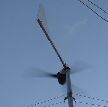
Havent had a play with FP units yet, I hope to do in the new year to harness a spot on my property with a near constant easterly breeze that for the most part isnt enough for a HS mill, Karl is getting me a couple and rewinding them to 24v delta fun and games.
The magnet and coil is low tech but it never dies untill the VS mull dies I found that varying the air gap controls the voltage to a large degree and a diode across the end of the wires stops the spikes and gives a clipped wave form at whatever the diode voltage is ZV. Looks like a saw tooth form in the scope, That was back in the valve days I then used a car tachometer recalibrated to requirements. No spike problems there.
For initial setup now I use a digital strobe tacho ebay special for 25 bucks and the magnet ring for permenant logging if ever I can get my gead around these picaxe thingoes.
I am playing with a 60 volt 50 amp DC brushed generator one left over from the old days for a big mill on the workshop at present waiting on a set of blades and some cooler weather to inspire me. have made a sensor for that, magnets epoxyied to a six inch alluminium disk behind the drive pulley need 1500 rpm for max output.
I tried the relay coil setup but found the volts went way to high the 25 turns on a ferrite rod was about the best compremise it will work down to 10 turns but air gap is to close for bush enginering.
All the best
Bob
Foolin Around |
| |
GWatPE
Senior Member

Joined: 01/09/2006
Location: AustraliaPosts: 2127 |
| Posted: 12:17am 19 Dec 2009 |
Copy link to clipboard |
Print this post |
|
Hi Pete,
here is the tacho cct that I use on my mill, and that worked on my F&P before.
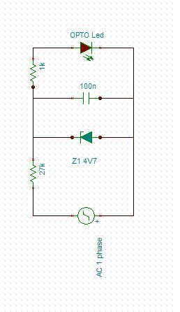
The opto coupler outputs are connected between the 5V and the micro input pin. I use a 33k pulldown resistor from the micro input to ground. There is no filter capacitance on the micro input.
The combination of 27k series resistor to the 0.1uF ceramic cap and 4V7 zener gives a good square wave drive to the opto LED. through the 1k limiting resistor. The zener gives asymetric clamping of the AC to form the sharp square wave, and prevent reverse bias to the opto LED.
The pics above do show that the rpm is not detected below 30. Depending on the system voltage, the 27k could be reduced on lower voltage systems. leave the other components the same. The 27k is good up to 70VAC. I measure directly between 2 phases, so no extra magnets or pickup coils etc. The output frequency of the windmill at low rpm will determine the lowest rpm measured.
This is a very simple cct and works on my AxFx mill with all the caps as well.
Gordon.
become more energy aware |
| |
VK4AYQ
Guru
Joined: 02/12/2009
Location: AustraliaPosts: 2539 |
| Posted: 01:31am 19 Dec 2009 |
Copy link to clipboard |
Print this post |
|
There is more ways of killing a chook than choking it with hot butter
Bob
Foolin Around |
| |
Downwind

Guru
Joined: 09/09/2009
Location: AustraliaPosts: 2333 |
| Posted: 03:58am 19 Dec 2009 |
Copy link to clipboard |
Print this post |
|
Thanks Gordon,
The circuit is basically what i had in mind and you have saved me the effot of working out the resistor values. (real hard job ha!)
I think one of the important things you pointed out is the need for the pulldown resistor on the micro side of opto. (Then again i thought the opto's were npn)
I have read several times that others had no luck using opto's and have wondered if they had a pulldown/pullup resistor in circuit or it wont work.
Bob,
You have already addressed the concerns i had with the coil. You have a good working circuit and think if you were to feed it into a micro than it might pay to put it through a comparitor or opamp to square the wave up and give some extra protection as these chips are cheap disposable fuses to me compared to damage to a micro.
The beauty about the circuit that Gordon posted is no need for extra wires down the mill as it is using one of the phase wires to sense from.
As Karl had commented he already has as many wires running down the tower as he wants.
Yes the relay coil will produce a high voltage spike.
I had used one as a sensor on a gearbox for reading rpm and was using the low side of the wave gated through a diode so the high voltage was not a issue.
Now choking a chook with butter? well the mind boggles on that one. Is that where buttered chicken comes from.
Pete.
Sometimes it just works |
| |
GWatPE
Senior Member
Joined: 01/09/2006
Location: AustraliaPosts: 2127 |
| Posted: 07:03am 19 Dec 2009 |
Copy link to clipboard |
Print this post |
|
Hi Pete,
Forgot to mention that the LED shown in the pic, is actually an LED in series with the opto LED. This gives a visual indication of the pulsing. Basically, if you see the LED blinking, then the pulses should appear on the micro input. 30rpm does not blink the LED very fast
The resistor can be pullup, or pulldown. I just happen to like the logic this way.
BTW, this is just a variant of Gizmo's original arrangement to drive the opto coupler. I use sharp 4pin optos.
I am unsure why PhillM's was noisy with caps. He has my version of a piclog. He now has reed switch and some magnets. He does not have slip rings, so a few extra wires were not a problem.
Gordon.
become more energy aware |
| |
KarlJ

Guru
Joined: 19/05/2008
Location: AustraliaPosts: 1178 |
| Posted: 11:16am 24 Dec 2009 |
Copy link to clipboard |
Print this post |
|
Sorry I hadn't been checking in on this thread, more concerned with getting the bastard on the pole!
I think the simple circuit is the ticket!
Luck favours the well prepared |
| |
Downwind
Guru
Joined: 09/09/2009
Location: AustraliaPosts: 2333 |
| Posted: 11:31am 24 Dec 2009 |
Copy link to clipboard |
Print this post |
|
Karl,
Enable email notice in your profile and you will get notice of all posts to topics you are involved in.
Merry Christmas to you.
Pete.
Sometimes it just works |
| |
| |
Page 2 of 2 |
