
|
|
Forum Index : Electronics : micro TIG
| Page 1 of 3 |
|||||
| Author | Message | ||||
| Dinges Senior Member Joined: 04/01/2008 Location: AlbaniaPosts: 510 |
Better start up a proper thread instead of messing up other's posts.... Just did some experimenting, not with the PC PSU but with the arc starting part, the high-voltage generator that superposes a RF high-voltage on the welding current. The trick is to add this HV without blowing up the PC PSU.... Below is the schematic, quickly thrown on a piece of paper. No fancy design, just using some components that were handy. The arcstarter with transformer works, the filter has yet to be built. 
Below an image of the gadget, with arcs (one in the spark gap, the other one the actual starting arc): 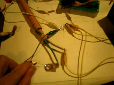
The nice thing is that it is RF high voltage, so you can't shock yourself with it; same idea as with a Tesla coil. In fact, the arc starter has a lot in common with a Tesla coil. Now, the trick is to superpose that HV on the welding power supply without blowing it up. By adding the HV in series, rather than parallel to the low-voltage welding current, the problem becomes a lot more manageable. Also, there's less that can go wrong with transformers than switchmode PSUs, in that respect, but will try the PC PSU as welding current supply first, with proper filtering. I think the filter as I've drawn it is overkill, compared to what I've seen in some commercial designs, but better safe than sorry. I bet a few kV will be one of the few ways to permanently disable one of those PC PSUs.... Lot more experiments to be done, but so far I'm pretty happy with the arc starter, which was basically thrown together on a whim - the HV generator (12Vdc in, 2.5kVac out) was just sitting in a corner of the desk, as I had built it a few weeks ago just for fun, with no particular intention of using it for anything useful: 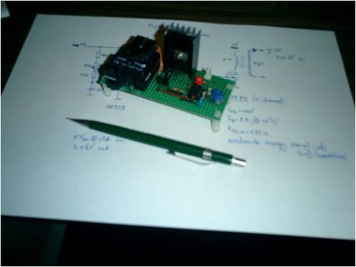
It uses a flyback transformer from either a laserprinter or copier. Forgot which. Quickly grabbed a ferrite tuning rod (ex AM radio/SW receiver), wound a transformer, got a spark gap out of one of the drawers (they used to be pretty common in older television sets) and a HV capacitor and threw something together with a few crocodile wires. And it even worked. And kept working after an hour of drawing sparks (HV is fun...) Drawing arcs from a finger doesn't hurt - no electrical shock, despite the high voltage, but after a few seconds the skin burns due to the heat of the arc. So proves that the arc starter is safe to use in that respect. Peter. (<-- keeping the electrons flowing) |
||||
| Dinges Senior Member Joined: 04/01/2008 Location: AlbaniaPosts: 510 |
Oztules, Just did another test on that PSU - without any extra sense resistor apart from the original PCB trace, and with the 2k pot set to zero, it current-limits to 4.4A. 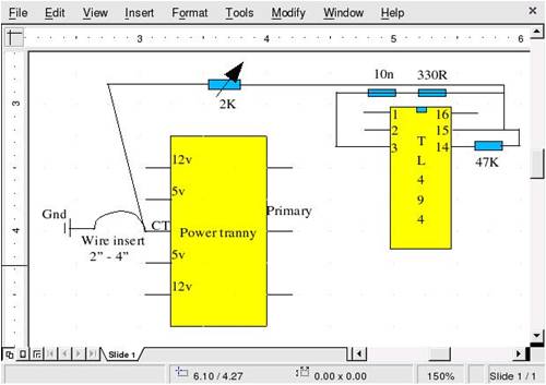
So, if you can live with that (i.e. if you only want to protect the PSU from short circuits), there's no need to add sense resistors to the transformer. This means you can use also those PSUs that do not have one of those flying leads (the ones without flying leads are hard to reliably mechanically fix a sense resistor to). For my purpose though, I want to be able to reduce current to, say, 100mA, so some added resistance will be needed. Oh - most likely the microTIG will not be made with a PC PSU, but a few transformers and a resistance bank, switched by relais via BCD switches. Neanderthal technology, but less that can go defect in the presence of RF high voltages generated by spark gaps.... Peter. (<-- UGH!) (that's Neanderthal for 'I just got a RF burn on my index finger and it hurts!') |
||||
| Dinges Senior Member Joined: 04/01/2008 Location: AlbaniaPosts: 510 |
Have drawn a few schematics to make the difference more clear. And the advantage, if I may say so. The original modification: 
Peter's modification of the modification: 
The difference is clear: the sense resistor is added in a different place. That's basically all there is to it, but it makes the difference between being able to (easily) convert all PC PSUs for current control, or only those with flying leads. It's possible to install the new Rsense on the PCB, not leaving it floating - when the no longer needed components at the output are removed (+5, -5, -12V), several completely unconnected PCB traces will appear. These can be used to re-route the ground lead, add a shunt resistor (just a bit of wire) and connect the sense wire to the TL494. 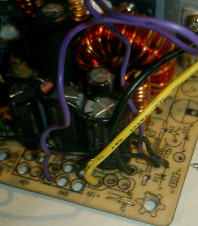
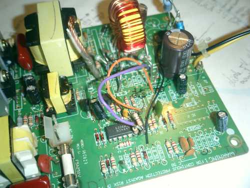
In the picture, the purple wire is the sense resistor, which connects from the original ground point of the PCB to a free pad; to that free pad is also soldered the thick black ground wire that leaves the PCB, and the ground for the voltage control potmeter. That's all there is to it - but it allows 100% of PC PSUs to be converted (as long as they have an unused 2nd opamp in the TL494) Peter. |
||||
| Janne Senior Member Joined: 20/06/2008 Location: FinlandPosts: 121 |
Nice.. once again the trusty computer PSU proves it's versatility. I assume this means you were also able to trace back the problems with the 555 in the HV start circuit ;) If at first you don't succeed, try again. My projects |
||||
| Dinges Senior Member Joined: 04/01/2008 Location: AlbaniaPosts: 510 |
Bad IC socket.... Peter. (<-- has Oztules' PC PSU modification royalties lying on his desk - a half-eaten candybar and 1.5m of string, as good as new) |
||||
oztules Guru Joined: 26/07/2007 Location: AustraliaPosts: 1686 |
Dinges, Looks a good way to modify the non-flying lead types... I have yet to see this type here.... but it must be somewhere I guess. About these royalties.... I have a sinking feeling I may not see the second half of that candy bar, and you will probably find some fiendish way of seeing off the string... so I guess I will have to wait till next time...wanders off mumbling ....... Interesting project you have there, will it ever do more than boring a hole in your finger you think? (oztules did feel better hearing of your HF/HV injuries  ) )
Well, got another regulator to fix/build so I'm off. ..........oztules Village idiot...or... just another hack out of his depth |
||||
| Dinges Senior Member Joined: 04/01/2008 Location: AlbaniaPosts: 510 |
Oztules, about half of my 15 or so PSUs were of the non-flying lead type - wish I had thought of this method before.... It's 1:30 AM now... wasted another perfectly good evening messing with a PC PSU.... After I had performed the finishing touches on the PSU, permanently wiring up the voltage and current control potmeters, adding dabs of hotglue to make things a bit more permanent, etc., I proceeded to 'reliablity test' the supply. Some would say I was just messing about, drawing sparks, but honestly, it was a reliability test.... And the PSU failed. I let the magic smoke out, but only a little. When the PSU is unloaded and I turn up the voltage all goes fine up till about 7V (on the previous 12V line), after which the PSU becomes unstable. If I turn it up a bit more, it shuts down - the TL494 stops oscillating (no sawtooth on pin 5 (CT) any more), no more output pulses on pin 8 and 11 (outputs of the transistors). Basically, the TL494 stops working - but, power on pin 12 remains a rocksteady 19.09 V, and pin4 (DTC) remains nice and low - which it couldn't be anything else, as both diodes that go to another control IC (LS 16802... doesn't ring a bell for me) are disconnected. Then, I noticed a tiny trace from the Feedback pin (3) of the TL494 to that LS16802, so I disconnected that one too, thinking that maybe it controlled output of the TL494 via pin3 - which it didn't, as the behaviour remained the same - turn up the voltage and, above a certain level, it stops, whilst the TL494 remains powered. Voltage on pin 3 (FB) then drops to zero, which probably makes sense since the oscillator is stopped. When the PSU is then unplugged and plugged in again after waiting for a few seconds, it can be powered up again (voltage slowly turned up until it becomes unstable again). So looks like there is still some latching going on that disappears at power-off, even though the associate IC (LS16802) is out of the loop, and I don't see any other ways to control the TL494 - how could the *oscillator* stop, fer crying out loud?! I'm actually beginning to suspect the TL494 now, may replace it tomorrow, as I don't see any other control signals going into the TL494: it remains powered on its pin 12, yet the oscillator stops, even though there's only a R and C on pin 5 and 6 to ground; no extra transistors that could disable the oscillator. Strange. Very strange. Peter. BTW: is RossW's IRC down? Edit: just recalled.... even when the TL494 was running, the waveshape of the sawtooth on pin 6 (CT) looked strange to me, different from what the datasheet shows. As I've never scoped that pin of a working PSU before, I disregarded it... but must check it out more tomorrow. Basically, the sawtooth oscillated with two different amplitudes - one very large (3V) sawtooth rise and fall, followed by many more (several tens or hundreds?) of oscillations of much smaller amplitude (about 1/10th of the large one?), and much higher frequency.... until it completely stops oscillating, as you turn the voltage potmeter up above about 7V. More edit: one thing I worried about earlier was the maximum negative voltage the TL494 can take on its opamp inputs, -0.3V; as my sense resistor is 19.6 milli-ohm, any loads above about 15A when the potmeter is set to '0' (i.e. minimum current) would cause it to develop more than its maximum rated -0.3V; and as a short-circuit can easily draw more than 15A out of the buffer capacitor... hm.... Maybe that explains the failure - a failure mode that couldn't happen in Oztules' original variant, as the current is measured directly at the transformer, not after the buffer elco.... Hm. Maybe my modification wasn't as clever as I thought. |
||||
| oztules Guru Joined: 26/07/2007 Location: AustraliaPosts: 1686 |
............odd Try a scope on vcc, and see if there are any spikes>40v making up the 19v rms.. the only thing I can think of that will stop the oscillator would be over voltage cut out. Even though you see 19v, there may be imposed spikes that the chip picks up.... particularly with no loads. Is it an atx or xt. If XT, then the spurious oscillations may get through from the boot strapping circuit.... and this may be what keeps it alive while shut down is achieved.... long shot. If not, is there any other chips that could self oscillate and cause spikes into the supply ??? Makes little sense I reckon. However, I don't know of any other status where the oscillator won't oscillate 
.............oztules Village idiot...or... just another hack out of his depth |
||||
| Dinges Senior Member Joined: 04/01/2008 Location: AlbaniaPosts: 510 |
Scoped pin 12 (Vcc) of the TL494 - squeeky clean DC at 19.09V. I'm actually getting more and more convinced it's a too large negative voltage spike that damaged the TL494 - it could happen because the buffer elco is *before* the sense resistor, not after, as in your original method. Even if that isn't what caused the damage in this particular case, it's at least something that *could* happen with this particular modification by me - something that can't happen with the Rsense in the transformer lead. A possible solution would be to place the Rsense between the output filter coil and the capacitor, so a current spike by discharging the output capacitors won't be sensed by it. Peter. (<-- having a hard time admitting Oztules did it better....) |
||||
| oztules Guru Joined: 26/07/2007 Location: AustraliaPosts: 1686 |
Hmmm, perhaps just isolate the track at the CT pins, and bridge the cut with your 4" of wire.. I might try that instead of lifting the flying lead out of the board... would look neater (not that it seems to bother animals such as myself). ...........oztules (still pondering his newfound wealth of half a candybar and a pristine ball of string on the other side of the world.... wonders at the exchange rate at the moment) Village idiot...or... just another hack out of his depth |
||||
| Tinker Guru Joined: 07/11/2007 Location: AustraliaPosts: 1904 |
Dinges, a practical question on your micro TIG machine. What are you using for a gas supply, some micro size bottle of gas suitable to weld ss or do you have to drag a full size bottle around? Unfortunately there is a monopoly of sorts with the gas supply in W. Australia, one has to rent the gas bottle - not possible to buy it I was told. Which makes it not economical for the experimenter with only occasional welding jobs. I really would like to experiment with a micro TIG set up if I could solve the gas problem. Klaus |
||||
| Dinges Senior Member Joined: 04/01/2008 Location: AlbaniaPosts: 510 |
Klaus, I have a 40L Argon bottle here (property, not rented) for the large TIG machine. Used a 10L bottle in the beginning, but it didn't last too long. The 40L bottle is a drag to haul around for a refill, but in the shop it sits on a cart along with the welding machine - easy to wheel around (as long as the floor is flat....) So gas is not one of the problems to solve for this project. Peter. |
||||
MacGyver Guru Joined: 12/05/2009 Location: United StatesPosts: 1329 |
[Quote=Tinker] Unfortunately there is a monopoly of sorts with the gas supply in W. Australia, one has to rent the gas bottle - not possible to buy it I was told. Thought I'd try to ease your pain a bit with this: In the States, it's called a "demurrage" fee. Not sure of the spelling. At any rate, it means you pay a small "rental" fee to whomever owns the bottle, but the up-side to that is that when it comes time for the bottle to be pressure tested or should anything go wrong with the valve or its need to be changed because of updated regulations, it's the owner's responsibility. I have welding-gas bottles of my own and went to get one refilled only to find that a new regulation required the valve be changed. The valve change along with the hydrostatic testing came to almost the cost of a brand new bottle. Had I "rented" the thing, all I would be out is the re-fill charge. Hope that makes you feel better about your situation. Nothing difficult is ever easy! Perhaps better stated in the words of Morgan Freeman, "Where there is no struggle, there is no progress!" Copeville, Texas |
||||
Don B Senior Member Joined: 27/09/2008 Location: AustraliaPosts: 190 |
Hi Peter, This might be completely irrelevant, but one thing that can cause an oscillator to run eratically is noise in its power supply. Maybe you need to bypass the power supply right at the chip supply pins. Regards Don B |
||||
KarlJ Guru Joined: 19/05/2008 Location: AustraliaPosts: 1178 |
Have you considered an F&P welder? one of our members built one, reckons it was a real beauty, easy to weld with and ran on the lawn mower..... Karl Luck favours the well prepared |
||||
| Dinges Senior Member Joined: 04/01/2008 Location: AlbaniaPosts: 510 |
Managed to put the magic smoke back into the little PSU. Turned out it was the TL494 that was defect. Below an image of the signal on the oscillator pin CT (pin 5) before replacement: 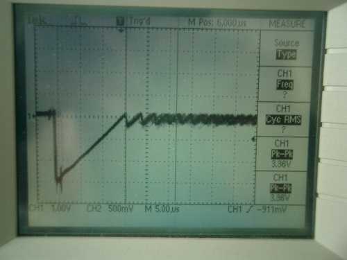
As can be seen, doesn't look healthy. After exchanging the TL494 for another one the PSU works again, and this is how the oscillator signal looks now: 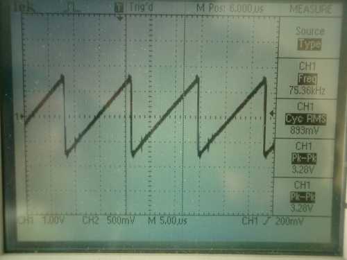
A few other things that changed about the PSU just by replacing TL494s, and which surprize me: 1). Previously, with the old TL494, the PSU ran unloaded fine. Now, it needs about 250-300mA load to remain stable; without that load, I can turn the voltage up to 29.5V, but when slowly turning it down again, it doesn't respond to the potmeter until well below the set value; in fact, have to turn the potmeter down to 3V before the output voltage drops suddenly from 29.5 to 3.0 V. Adding 110 ohm load cures this. Now, it's generally good practice to never run a switchmode PSU unloaded. However, I had not expected that this behaviour depended so much on an individual TL494; I was expecting it was more related to other design issues of the power supply. 2). maximum output voltage has increased, from 28.5V originally to 29.3V; again, wouldn't have expected an individual TL494 to have so much impact on this. Probably enough variation in properties to cause this difference (perhaps a fraction of a percent less dead-time?) Finally, a circuit diagram to explain what I think went wrong with my implementation of Oztules' modification: 
Above is an explanation of what I think caused the TL494 to go defect. In my modification, a short-circuit would discharge the capacitor and could easily draw a current spike of much more than 15A; this would develop more than -0.3V over the sense resistor, which could damage the inputs of the opamps of the TL494, which can't take more than -0.3V (abs.maximum rating). This current/voltage spike was never an issue with Oztules' original modification, as the sense resistor won't see current spikes of the output capacitor. I haven't tried it yet, but placing the sense resistor in front of the output capacitor ought to solve this problem. Karl: do you have a link for that F&P welder? Would be interested in reading it (unlikely to build one though). Peter. Edit: just ran a test, discharging an identical capacitor (560u/35V charged till 10.7V) over the original shunt resistor (19.6 milli-ohm). It results in a voltage developed over the shunt resistor of slightly over 1V, so a discharge current spike of 50A. Now, this was at 10.7V. At nearly 30V, that spike may be about 3 times as large, yielding a negative voltage of -3.0 V on the opamp inputs. Definitely far above its maximum rating. |
||||
| Dinges Senior Member Joined: 04/01/2008 Location: AlbaniaPosts: 510 |
Dinges waves away some more magic smoke.... Another TL494 bit the dust (actually, a KA7500B). After moving the sense resistor to a place before the output capacitor and powering it up again, the PSU was very unstable. All kinds of nasty sounds coming from the transformer. And then it died. Again scoped the oscillator pin of the TL494, and again no oscillations, whilst the IC still received 19V power. After replacing the TL494 I decided to do it properly, the Oztules' way.... removed the output transformer, unsoldered the two leads that went to the common-pin of the transformer, bent the leads up, added about 7cm of wire and a small sense wire (basically adding a flying lead to the transformer), added heatshrink to prevent shortcircuits and make it mechanically stronger, and resoldered it. And now it works - properly. I can abuse it in every kind of way and it doesn't act up. Finally. Groan. With the help of the little clown I determined that with 700 ohm the supply limited at 12A, so I'll rig up a potmeter (1k pot + 2k4 resistance in parallel; not sure what (anti-)log characteristic it'll end up with, but it will have to do) Now, what was it I was going to do again with this supply? Almost forgot why I set out to modify it in the first place.... Ah well. After all this messing about, I can use a little extra energy. Peter. (<-- reaches for a half-eaten, few days old candybar that was lying on the desk) |
||||
| vasi Guru Joined: 23/03/2007 Location: RomaniaPosts: 1697 |
Hi guys, I found this on CNCPro Yahoo Group. Vasi Hobbit name: Togo Toadfoot of Frogmorton Elvish name: Mablung Miriel Beyound Arduino Lang |
||||
| oztules Guru Joined: 26/07/2007 Location: AustraliaPosts: 1686 |
I was about to giggle at your "seeing the righteous path...." and even a bit at your misfortune (self inflicted is the best kind)..... but then I noticed you have eaten half my profits..... and I'm left with a ball of string 
I'm not sure if my way is the "proper"way, but you have to admit it makes these things near indestructible. might have a quick chuckle anyway... candy bar or no candy bar. ..........oztules Village idiot...or... just another hack out of his depth |
||||
| Dinges Senior Member Joined: 04/01/2008 Location: AlbaniaPosts: 510 |
(Peter dangles a candy bar in front of Oztules in hope of picking his brain some more) Oztules, have you ever done a 0-55V modification yourself? If so, how did you power the TL494? I've modified a small 200W PSU so far that the current and voltage control loops are closed and regulation is stable. Output voltage goes up to 59V and it's at the moment (for safety) current-limited at .8A. The flying lead (common/ground) of the transformer is disconnected from the rest of the circuit now, and a full bridge rectifier has been made with BYW95C diodes (ultrafast, 3A, 600V, t-rr=250ns, a tad slower than the original diodes) However, I don't succeed in powering the TL494 off the output of the transformer, even though I'm using the 5V windings, rectifying them separately (output=58V w.r.t. ground) and then regulating with a small zener/resistor/capacitor-circuit to 16V. 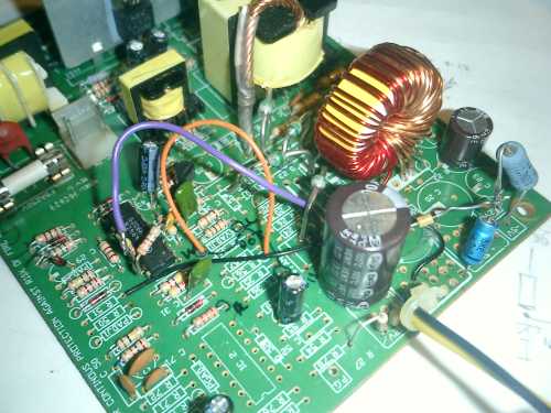
For some reason, when I feed this +16V to the TL494 (via a small diode) the series lightbulb (yeah, I'm experimenting with a 100W lightbulb in series with the 240Vac - I ended up with some pretty unhappy switching transistors and rectifier diodes, not to mention a loud ringing in my ear after it all went *bang*), the PSU starts oscillating and the series lightbulb repeatedly flashes brightly at about 2-3 Hz. Not good.... When I power the TL494 from a 12V battery all is hunky dory - as long as I connect the battery *before* applying power to the circuit, otherwise it releases magic smoke. I'd like to have a self-contained PSU, without the need for a secondary powersupply just for the TL494. Even if I were to add a separate small 12V powersupply just to supply the TL494, I'd have to make a circuit that ensures the PC PSU only switches on *after* the 12V for the TL494 is on and stabilized. As you can see, hardly an elegant solution. Plugging the PC powersupply in without a voltage present on the Vcc (pin 12) of the TL494 causes loud bangs and magic smoke to escape. See image below for those components who valiantly offered their life for the benefit of the advancement of science: 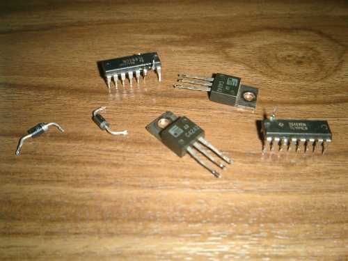
(and here's the noble, undervalued incandescent lightbulb that now offers its services for the protection of the replacement semiconductors:) 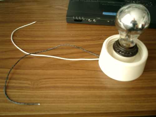
So, in short, the question is: how did you go about this business of powering the TL494, if you've done a 5-55V modification yourself yet? Peter. (<-- eyes the candy bar, smacks his lips but decides to not open it just yet - may need it for bribery) |
||||
| Page 1 of 3 |
|||||
| The Back Shed's forum code is written, and hosted, in Australia. | © JAQ Software 2026 |
