| |
  Page 3 of 3 Page 3 of 3 |
| Author |
Message |
Dinges
Senior Member

Joined: 04/01/2008
Location: AlbaniaPosts: 510 |
| Posted: 03:36pm 27 Jan 2010 |
 Copy link to clipboard Copy link to clipboard |
 Print this post |
|
Looks like I have another welding machine to add to the collection....
Put in a new IGBT module (different type/brand than the original, but same ratings) in the Kemppi and it works fine again. Very nice, stable arc, down to 5A. And has the option for TIG. I think this is the beginning of a beautiful friendship.
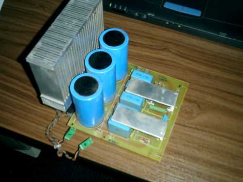
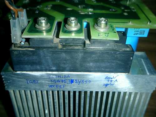
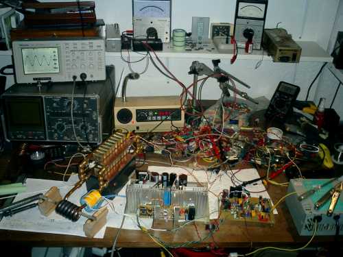
Just for giggles, here's the power section - your basic half-bridge as in a PC PSU, but at a little bit beefier.
In other news.... been playing with the induction heater too. Have built a new tank circuit with 18 pieces .15uF/440Vac capacitors and a new work coil, made of 8mm copper pipe.
Everything is still powered by a modified PC PSU, which shut-down when I increased output power to over 200W. Turned out RF fed back into the PSU and caused it to trigger a fault. A few turns of the low-voltage supply wires through a ferrite toroid bead (common-mode choke) solved that problem.
After initial tests at low power I turned up the variac to the full 230Vac.... pushing about 1000W of power into that steel rod, till it got red hot (in about 20-25 seconds).
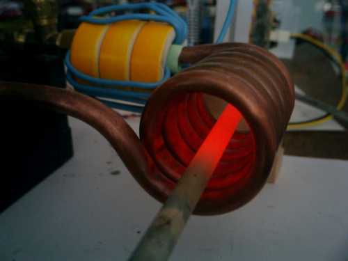
Inverter stays cold at that powerlevel, so I'm very impressed. Looks like, as far as the inverter is concerned, about double output power may be possible.
Peter.
Edited by Dinges 2010-01-29 |
| |
Greenbelt

Guru

Joined: 11/01/2009
Location: United StatesPosts: 566 |
| Posted: 06:14am 28 Jan 2010 |
Copy link to clipboard |
Print this post |
|
Peter' You have an audience, they are totatly captivated by
your unequaled creativity.
Fame=Junk * time^2  
    
Time has proven that I am blind to the Obvious, some of the above may be True? |
| |
oztules

Guru
Joined: 26/07/2007
Location: AustraliaPosts: 1686 |
| Posted: 10:37am 28 Jan 2010 |
Copy link to clipboard |
Print this post |
|
Peter,
Let me be the first to say, I am liking the way your bench is starting to look more like mine. I think if you go on in this vein, Joe's brother (WXYZSCIENCE) may donate his buffalo knife just to set it off properly..  ... (His desk is still the level we need to work towards.) ... (His desk is still the level we need to work towards.)
Is it correct that that last picture is powered by a converted PSU?
What will you use them for next??
Well done as always.
............oztules
Village idiot...or... just another hack out of his depth |
| |
Downwind

Guru
Joined: 09/09/2009
Location: AustraliaPosts: 2333 |
| Posted: 11:31am 28 Jan 2010 |
Copy link to clipboard |
Print this post |
|
Hi Dinges,
Also impressed with your progress in this thread. 
Still trying to convince myself to build one over the oxy-torch that gets little use nowdays.
I am yet to get my head around the pc psu mod and had started building one some time back, but tooooooooo many other projects took over. So you and Oz can expect some dumb questions of how to transform a crap psu supply into a valuable tool.
I like your work.
Pete.
Sometimes it just works |
| |
Dinges
Senior Member
Joined: 04/01/2008
Location: AlbaniaPosts: 510 |
| Posted: 05:36pm 28 Jan 2010 |
Copy link to clipboard |
Print this post |
|
Thanks for the words of encouragement, all.
[quote=Oztules]Let me be the first to say, I am liking the way your bench is starting to look more like mine.[/quote]
Yeah, I recall the picture of the workbench of Joe's brother.... Would you believe me if I told you that last weekend I cleaned up my desk for the first time in 8 months, and that what you see in my picture above is what the desk looks like *after* cleaning? I kid you not. I'll leave it up to your imagination as to what it looked like before.
[quote]Is it correct that that last picture is powered by a converted PSU?[/quote]
Should have been more clear: the driver board was powered by a PC PSU. And initially I used a PC PSU for low-voltage/low-power input to the inverter as well. But in that picture with the glowing rod, the inverter is powered with 230Vac mains and the drive signal (138kHz) being supplied by a function generator, manually tuning for resonance. Those PC PSUs can be pushed very far, but 1kW I'd think would be a bit too far.
Am now wrestling with the PLL controller that drives the inverter. It doesn't lock onto the frequency. Have noticed a few bugs in the board and am now working to clear those problems. Iamsmooth's induction heater tutorial is of great help in that.
Peter. |
| |
Downwind
Guru
Joined: 09/09/2009
Location: AustraliaPosts: 2333 |
| Posted: 06:30am 29 Jan 2010 |
Copy link to clipboard |
Print this post |
|
Good to know i am not alone with the messy work bench
Perhaps we should start a thread of who has the messier work bench.
I hate to say it but this was mine before Christmas and its only got worst since.

I have a theory that those with a tidy bench dont do much on the bench.
For me i do more on the floor as i cant find room on the bench.
I no sooner clean it up and it looks the same, almost over night.
Pete.
Ps. i know where every thing is ..... Its on the bench!!
Sometimes it just works |
| |
Dinges
Senior Member
Joined: 04/01/2008
Location: AlbaniaPosts: 510 |
| Posted: 10:24pm 30 Jan 2010 |
Copy link to clipboard |
Print this post |
|
Succes at last!
After messing about with the induction heater's control board for 3 evenings and one full day, it seems to finally be working properly now. After many hours messing with comparators that preferred to oscillate rather than compare, comparators that saw up to -15V input whereas they can't take more than -0.3V, leakage currents due to solder flux that messed everything up, phase-errors introduced by too long transit times in NAND-inverters, etc.etc, and a reversed diode that prevented the loop filter's control signal from ever reaching the voltage controlled oscillator , most major bugs seem to have been ironed out finally.
So now it's possible to run the induction heater 'automatically', i.e. without needing to tune for resonance manually, or adjusting the variac to prevent magic smoke escaping: the PLL now tunes for exact resonance and the tank over-voltage protection kicks in when it gets above about 60V, protecting the inverter from too high loads and running unloaded. (there's one thing induction heaters can't stand and that's running unloaded - not unlike windturbines). And the turn-on sequence doesn't matter, i.e whether you first turn on the PLL and then the inverter, or otherwise - nothing blows. That's good.
Still some modifications to be done though, as the inverter overcurrent safety doesn't latch, but that will be solved as well.
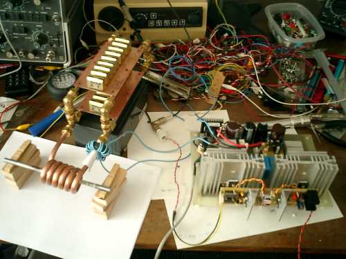
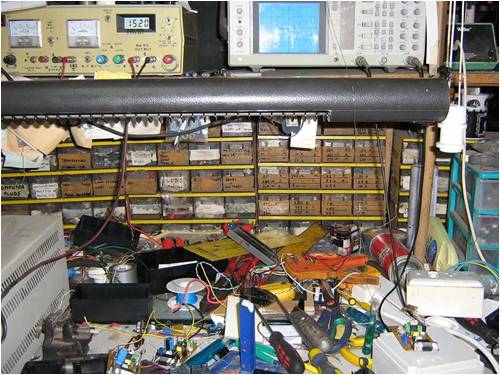
To satisfy the visual aspect, here's a picture of the workbench. Somewhere in that mess there's a working induction heater.
To the left the tank circuit, with workpiece in it (hard to see, but glowing red-hot as 850W of RF is being pushed into it). It's still working off the variac, but more as a precaution to quickly reduce voltage if needed - it's now continuously working on 230Vac.
The scope above shows the waveshape - perfectly locked onto the resonant frequency (which varies, depending on the size of the load, i.e. workpiece, and temperature it has). Amplitude is about 60Vac, which means that about 130A of current circulates in the tank circuit. And that shows: the 8mm copper pipes get *hot*, the workcoil gets scorching hot, and the capacitors get warm (about 50 deg. C) after a while. Not surprizing, as each has to handle about 7.5A at 140kHz... So watercooling is most definitely not a luxury, not even at this relatively low power level of 850W, not if you want to run it for more than a few minutes at a time. Have pushed output power up to 1000W without problems, but don't want to get much higher because of the capacitorbank that's becoming the limiting factor
The analog meter to the above-right of the scope shows the tank voltage as measured by the controller, about 60V. Nice to have an analog display of tank voltage, and see how it rises as the workpiece starts to glow, after which over-voltage limit kicks in and reduces power to a safe 150W.
The yellow/white powdered iron toroids transfer the energy from the inverter to the tank circuit. Primary contains 14 turns of wire (still have to optimize this part; less turns may be a possibility, without the inverter protesting). Toroids stay cool, to my surprize, so will use these in the final construction too.
To the right of the tank circuit, the inverter - a half bridge with 2 MTW14N50E 's (I ran out of IRFP460s.... ). The cooling fins of the FETs stay cool, don't get above 35C even after extended running at 850W, so that's good too.
To the right of the inverter is the PLL control circuit. Contains its own 15V regulated power supply. A 4046 takes care of the PLL/VCO business. Various comparators do the signal processing and provide some security features, to protect against tank overvoltage and inverter overcurrent. When an error is triggered, power gets reduced to a safe level by detuning the VCO to a higher frequency (thus limiting power throughput) and lighting a LED (and in the final build, buzzing a buzzer). After resetting the error (preferrably after setting the power-control potmeter a tad lower), it starts locking and heating at full (set) power again.
The DMM at the top-right indicates the VCO input voltage, which determines the VCO's frequency. Should be somewhere between 1-14V, preferably being at the mid-point, 7V, but at 6V it's close enough for the moment, as there's still plenty of headroom to regulate below and above the resonant frequency.
To the right of the PLL, the infamous Oztules PC PSU, which provides all the power for the control board and gatedriver, at 24V.
And this is what all that fancy electronics does....
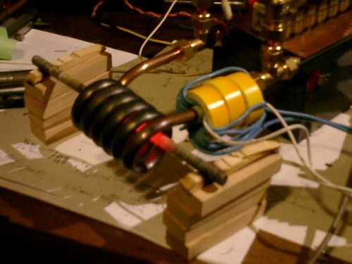
Looks much the same as the image of a glowing steel rod a few posts before, only this time it does it all automatically - just press the start button, and press stop when finished.
Tried out whether I could get a workpiece hot enough for brazing - alas, didn't work. It's getting close, but not there quite yet. 850W isn't much power either. But I don't want to push this machine much higher, we'll save that for the follow-up project (which will use a ready-made 7.2kVA full-bridge inverter; as I can't draw more than 3700W from single-phase grid anyway, that seems sturdy enough).
That's it - long writeup, but not nearly as long as it took to get it into its present working state. Next task is to debug the last errors (esp. inverter current error latching circuit) and then start building it into its cabinet, an old PC mini-tower.
Peter. |
| |
Bryan1

Guru
Joined: 22/02/2006
Location: AustraliaPosts: 1209 |
| Posted: 04:35am 31 Jan 2010 |
Copy link to clipboard |
Print this post |
|
G'day Dinges,
That project is looking great mate and the way that rod heats to glowing this project could also be good for hardening and tempering tools etc. The idea get the part upto soaking temp, drop in water,oil etc to harden then just set the induction heater to the preset tempering temp, get to temp then turn the thing off.
As far as a comp on the dirtiest work bench's I should really take some pic's of my shed bench's. Today I needed a 2x1/2" seal for the mincer project I'm doing for my mate. I must of pulled around 80 seals out of a couple of box's and just threw the seals in a pile for later sorting. Wouldn't ya know it one of the last seals I found was the one I was looking for.....
Cheers Bryan |
| |
| |
Page 3 of 3 |
