
|
|
Forum Index : Electronics : 433.92Mhz Wireless data antenna
| Author | Message | ||||
Downwind Guru Joined: 09/09/2009 Location: AustraliaPosts: 2333 |
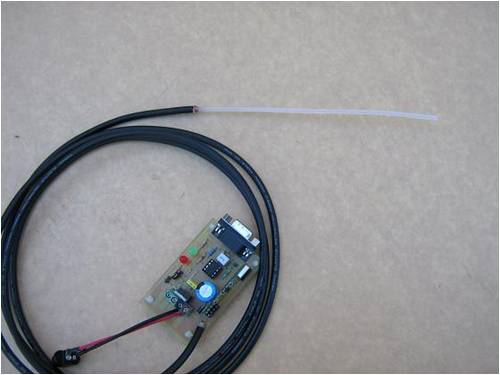
I have been building an anemometer with wireless data from a 433.92 Mhz TX & RX modules. The signal reception was poor to say the least, with gray spots in reception every where inside and intermittent data streams of corrupt data. Several antenna styles tried from bought rubber ducky style, to straight wire at 1/4,1/2,full wave and little improvement. In desperation i decided to try mounting the antenna away from the circuit. This required some coax cable and in stripping the outer back, i got an idea to use the inner conductor with the outer shield removed for the antenna. The outer removed and the exposed inner trimmed off at 172mm (1/4 wave ) above where the outer shield stopped. In the first attempt, i passed the inner through a hole drilled in a piece of copper clad circuit board and soldered the outer to the copper clad. The inner conductor was connected to the antenna pin on the circuit board and the outer shield connected to the negative on the pcb. This gave a huge difference in reception with constant valid data. I only had 75 ohm coax for the first one, but think 50 ohm would be better. Today i picked up 2+m of 50 ohm and with 172 mm of inner exposed and no ground plate, the coax connected to the receiver end (same connections as with the TX end) i had a even better reception. I feel it is worth while to do for anyone using 433.92 mhz modules for data transmittion. It allows for the antenna to be moved and mounted for better reception if needed. Any input on improvement from anyone with antenna knowledge would be helpful. Only other tips are use a coax that has some copper conductors in the outer shield so it can be soldered to the pcb, and the inner conductor should be a solid core and not multi strand as in some 50 ohm coax. A blob of silicone on the end and around where the outer sheath finishes to keep water out. 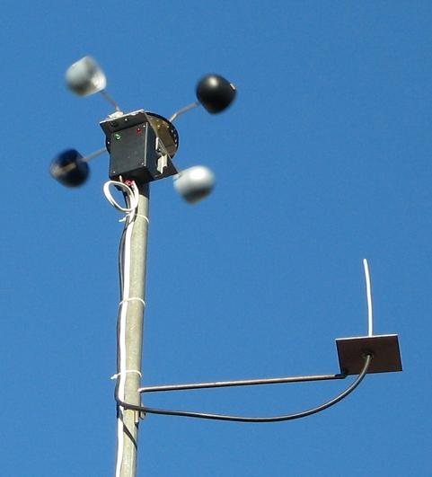
Pete. Sometimes it just works |
||||
| davef Guru Joined: 14/05/2006 Location: New ZealandPosts: 499 |
Search for <coaxial sleeve antenna>. I believe you need the other half of the dipole which is decoupled from the feedline for best performance. 1/2 wavelength would be the best but you need a balun to get it "closer to theory". Not sure what you mean by full wavelength. Matching to it would not be straight forward. The ground plane for a 1/4 wavelength antenna should also be a 1/4 wavelength or bigger and usually tilt down from the feedpoint at about 45 degrees. See <ground plane vertical antenna> Do you want omni-directional or could you use a small Yagi antenna? |
||||
| Downwind Guru Joined: 09/09/2009 Location: AustraliaPosts: 2333 |
Hi Davef, Im not the brightest light on the tree when it comes to antenna design. I need something better than 344mm (or 172mm)of hookup wire dangling in the breaze as what is normally recommended for the modules. Omni-directional preferred but what do you recommend. Would like to keep it simple if possiable for other constructors, as intend to use the TX & TR modules in a few wireless data circuits for data logging. So the RX end will more than likely end up inside and dont wish for something to big or ugly. Open to your thoughts and a bit of help. So far the coax has given a marked improvement and any further improvement would be Great 
Pete. Sometimes it just works |
||||
| GWatPE Senior Member Joined: 01/09/2006 Location: AustraliaPosts: 2127 |
Hi Pete, I have also tried the bared back coax antenna. I had better success than with the single wire soldered to the TX module. I did keep the length bared the same as the single wire. I used`the teflon type coax, thin. I now use the external antenna used on some WiFi routers. These are not specifically made for the job, but I have most reliability with them. Gordon. become more energy aware |
||||
| Downwind Guru Joined: 09/09/2009 Location: AustraliaPosts: 2333 |
Gordon what do you mean by bared back coax antenna?? Pete. Sometimes it just works |
||||
| GWatPE Senior Member Joined: 01/09/2006 Location: AustraliaPosts: 2127 |
Hi Pete, just like your own, but I used the thin Teflon coax. Gordon. become more energy aware |
||||
| Downwind Guru Joined: 09/09/2009 Location: AustraliaPosts: 2333 |
Thanks for the input so far guys. I put together a 1/4 wave vertical ground plane antenna. Thus far have only had it on the receiver end and have good results from it. I intend to mounting it on the transmitter end but in reading i see that poles and the likes give interference. The thought to mount it directly above the anemometer came to mind but not sure on what effect the spinning, whirling, gizmo beneath the antenna will cause. Any thoughts on this? The intended mounting would place it around 200-300mm above the anemometer. Or would i be better to mount it off to one side as the present antenna is in the photo above. Pete. Sometimes it just works |
||||
| davef Guru Joined: 14/05/2006 Location: New ZealandPosts: 499 |
For omni-directional vertically polarised operation some options for increased gain: - 5/8 wavelength, added bonus they are relatively ground independent - collinear, maybe up to 6dB of gain. The Amateur Radio Antenna Handbook is an excellent basic antenna book. There is an amateur band at 420-440MHz, so any designs for that band would not require scaling for your requirements. You will need to follow a set of plans to a "tee". IE, +/- 1mm type accuracy, unless you have an antenna testing range and know how to tune for best performance. If the RX ends up inside how omni-directional does the antenna have to be? If you could tolerate a bandwidth of say 60 degrees you could get some significant gain shaping the antenna pattern, ie a corner reflector (vertical) or maybe some other antenna with about 6dB or so of gain. Even a 3 element Yagi could be reasonable broad and give you 4-6dB of gain. BTW, 6dB is 4 times the signal level. Does the RX move around inside this building? What distance is it to the TX? |
||||
| Downwind Guru Joined: 09/09/2009 Location: AustraliaPosts: 2333 |
Thanks Davef, I followed up on your other suggestions and got some good ideas and will look into these to. On a scale of 1 to 10 of antenna knowledge im at 1. The intension for the RX end will be in a fixed spot and not moved around. At present the distance is only about 35m from TX to RX but would like for closer to 100m ability. The hard part about this is the end location is unknown, because i would like to put together some circuits for wireless data for use with data logging that others can build, making the end locations and conditions unknown. For now i need to be able to get reasonable signal strength for consistent data to make the project worth while attempting. What i would like to construct is Tx end that would send data from the battery shed, anemometer,water tank, windmill or whatever to a RX station that could have a lcd display to show which ever function chosen. The Rx end would write the data to eeprom or SD card for storage to be downloaded later. For this reason the RX end would be located in the house and the more compact the RX antenna is the better, but this might be at the cost of lesser reception locations. If you were to send data from your back shed to where the computer is or the kitchen is how would you best tackle the antenna?? Any thoughts to narrow the ball park would be appreciated. If i can save countless hours researching and building/testing by a bit of advice from others experience and knowledge i will take it. Pete. Sometimes it just works |
||||
| GWatPE Senior Member Joined: 01/09/2006 Location: AustraliaPosts: 2127 |
Hi Pete, the data logger should be be positioned as to only log valid data, with no gaps. How accurate the logging needs to be will be determined by the final data use. I log the source. I view the logged data remotely. The RF units have to share a similar band to other low power devices. I found that as the number of radio units increases, more data corruption occurs. I have 7 units sharing the same band now and reception is becoming flaky. Gordon. become more energy aware |
||||
| Downwind Guru Joined: 09/09/2009 Location: AustraliaPosts: 2333 |
Good point Gordon. I had considered similar but was quoting what i would like to be able to do. As you point out it might not be as practical. I find with each increase in quality of signal the corrupt data gets less. At present i get 1 corrupt data string about every 200-500 lines, where as with a lesser antenna i got 1 valid data string every 15 - 20 lines. I could live with 1 in 200 and it is filtered out anyway. This is presently not over a long distance though. Was not intending on a top of the range circuit design, rather something practical to build that simple enough for the would be electronic tinker to have a go at. A base design that could be added to if needed. ( be happy if you care to kick any thoughts in on this to) Do you use the same baud rate for you data on all 7 units. How do you do the timing of the signals, or do you just work on a hit and miss (as most do ) and get corrupt data from transmitter data overlaps. I can see how 7 units all chattering away would confuse any poor little micro 
Pete. Sometimes it just works |
||||
| davef Guru Joined: 14/05/2006 Location: New ZealandPosts: 499 |
As well as antenna issues there appear there could be some communications issues here as well. What modules are you using? There has been some traffic, even on this forum, about poor signal recovery from some types of RX modules. To get further information try searching AVRfreaks and search using words like <rf modules> <manchester encoding>. Budget modules, ie not using appropriate modulation and demodulation processes just don't cut it in weak signal applications. Getting reasonable throughput without controlling transmitters is problematic. If I wanted to have 7 units transmitting I would be using them in a master-slave setup. Unfortunately, this requires RX and TX at each end. Collision avoidance in a uncontrolled system is a headache. Read up on RS485 and the lengths they go to try and avoid collisions. Then have a look at I2C and CAN protocols to see how it can be more effectively done. Depending on your polling rate and the amount of data you are trying to shift I would consider the master telling each slave unit to "give me your information", and then poll each outstation in turn. The data you want to apply some CRC checks and ask for re-transmission of corrupt data. A X modem protocol is probably enough for this application. Or, send the data three times and if all three are the same consider it valid. If not just poll that station again. Happy reading! |
||||
| Downwind Guru Joined: 09/09/2009 Location: AustraliaPosts: 2333 |
Presently using the modules sold by jaycar ( the various types and styles are large when you search them and would like to use a local supplied module that is available widely). http://www.jaycar.com.au/products_uploaded/ZW3100(mod).pdf http://www.jaycar.com.au/products_uploaded/ZW3102(mod).pdf Some of the postings on the 433.92mhz modules here has been from myself and things i have found out with them. I agree with master / slave setup for multiable modules and had consider using this, as a cost of around $10.00 for the extra receiver per station is not that expensive for reliable data, if more than set is used. I2C protocol with master / slave operation and validation of data etc is in the code and only a few extra components needed to use it. Not to concerned about that part, other than a pic would need to be used for a I2C slave as you cant set a picaxe up to be a I2C slave, it can only be a master. What i am more concerned about, is good signal reception to start with. The rest can be easily changed but without good communication between the TX & RX modules to begin with, the rest is pointless regardless of any method used or weather it is 1 - 10 modules. Its not good if the only spot you get reception is standing on one leg in the corner, holding it precisely 1.45 mtr off the floor. (if you know what i mean) Its not that bad. Its workable, but any improvement would be good. Pete Sometimes it just works |
||||
| davef Guru Joined: 14/05/2006 Location: New ZealandPosts: 499 |
BTW links don't work for me so went to Jaycar. I can't read the part number on the RX IC. But ASK and the price tell me that these are not high performance items. For any RF system, it comes down to the following: - choice of frequency - TX power level - Antenna gain - RX senstivity - choice of modulation type - signal processing Seeing as you already have the modules the only options that I see are: - added power amplifiers - added RX LNAs - better antennas - signal processing Is there some data on TX power and RX sensitivity? The antenna stuff has been covered . . . any comments on that? This leaves signal processing. I don't know if manchester encoding will help you with ASK. It was going to help me with the Texas Instruments CC series and FSK. |
||||
| GWatPE Senior Member Joined: 01/09/2006 Location: AustraliaPosts: 2127 |
Hi Dave, data encoding is restricted to the data types allowed in the picaxe system for COMMS. There maybe other options with a PIC if you design specially. The cheap units are not high performance as you have pointed out, but they are cheap. Good for learning. I would like to look at X-Bee systems. Gordon. become more energy aware |
||||
| Downwind Guru Joined: 09/09/2009 Location: AustraliaPosts: 2333 |
Thanks Dave, Data on the modules is the hard part to find i have searched hi and low and only been able to find data in Chinese (not much good to me). Yes they are low power and cheap and is why i would like to squeeze every last bit out of them. There is always limitations unless you spend big $$ and am fully aware of this. For the average home builder these modules will work ok and are simple enough to use. I see little point in creating something that is complicated to use and to expensive for others to have a go at. As i have said several times it is not intended to be a bells and whistles project (I will leave that one to Gordon as he it well on the road to this) but rather a system others can build and learn from. There seems to be some interest in basic data logging and not all have the skills and resources to tackle a complicated project but would like to start somewhere. As for the antenna, i have gleemed some good information from your recommendations and am getting reasonable results from a vertical ground plane ant. Will post any further developments as they happen. Still much to take in and time has been limited. I have read many sites and comments on these modules and most end up as waffle with not real information. As i and Gordon has found the only way to understand these modules is to put them into an application and work from there, finding ways around the limitations. Pete. Sometimes it just works |
||||
| Downwind Guru Joined: 09/09/2009 Location: AustraliaPosts: 2333 |
With transmitting and receiving data from the 433mhz modules one thing that was worked out when i went to send a Word value (W register) was it had trouble with the start and end of each data byte. So data was then sent in Ascii code and received in ascii code and this gave good results and a lot less filtering of data required. Several blocks of non ascii data is transmitted first to wake up the receiver and then ascii data transmitted followed by a block of non ascii data between each block of ascii data, to give a stop/start mark to each ascii block. The receiving picaxe will ignore all data that is non ascii if it is told to read ascii only. For example [code] serout TX ,T2400,($aa,$aa,$aa,#code,$aa,#pulse_in) [/code] [code] serin RX ,T2400,#code,#pulse_in [/code] Also allows for word values to be sent in a single command as the above example "pulse_in" was a word value. By using ascii it got rid of a lot of the garbage that was picked up by the receiver and reduced to amount of filtering of valid data greatly. Pete. Sometimes it just works |
||||
