
|
|
Forum Index : Electronics : beginning picaxe for old dogs
| Page 1 of 5 |
|||||
| Author | Message | ||||
Downwind Guru Joined: 09/09/2009 Location: AustraliaPosts: 2333 |
Beginning picaxe for old dogs. They say you cant teach an old dog new tricks. I would like to try to teach some of you old dogs out there picaxe micro controllers. This will be a hands on activity using a 08M picaxe chip ( 8 pin chip) Make 2010 a year to learn how to use a micro and you will have a lot of fun for years to come with the vast amount of uses you will find to use them for. More than likely will wished you done it earlier. ( even if it is only to entertain the grand kids with) Heres an offer to kick off a new area to the forum on using picaxe chips, starting at a beginners level. The aim being to give a opportunity to anyone who has been interested to have a play with these great little micro controllers but don�t know where to start or anything about programming one. Its back to basics and work forward from there. One needs to learn how to use a few simple commands and how to get the program written and into the chip. The scope of what you can do with these micros is almost endless and is only limited by your ideas and knowledge. We all make mistakes with programming and its frustrating when we don�t understand otherwise or where you went wrong. ( or just cant see the error Doh!) Often the information reads like Chinese and you would understand if they spoke English. We need to be able to ask someone so we can move forward and is where this thread is intended to help. To start with it will be based around the 08M picaxe as it is the cheapest and will do all that is needed to get an understanding on programming and how to use them. To move to bigger chips later is the same programming functions just with different pin numbers and more pins as inputs and outputs. To start with it will be as simple as switching leds on and off using program control, to get use to assembling a program and dumping it into the picaxe. This is so easy but can be daunting for the first few times if never used a micro before. The Picaxe was developed as a learning chip for students and has very simple instructions. (why should the kids have all the fun, its our turn to play ) To switch a led on connected to output 4, its as simple as giving the picaxe this instruction. ######################## High 4 Pause 200 Low 4 ######################### This will switch pin 4 (output) to 5v+ (high) then wait 200 milliseconds (1/5 of a second) and switch pin 4 low or negative. If we add a �label� of MAIN: to the program and a GOTO statement it will then repeat the operation over and over. #################### Main: High 4 Pause 200 Low 4 Pause 200 Goto main ######################## This will flash a led connected to pin 4 every 200 Ms. As when it gets to the bottom of the program it is told to go back to the top and start over. Then we can add in more leds to flash and use different commands to do other things. Once some basic commands and instructions are understood we can look at how to write this into a program, so it is easier to follow and easier to make changes to. Each step is a progressive stage and in a short time you will have the basic idea of how to use these micros and an understanding to programming. Moving onto how to read a analog to digital converter pin and where to put the data and how to use the data. Ie: using variables b0, b1, b2,----- b13. Its all easy if you start at the beginning and work forward. I must admit the examples supplied by Microchip are vague to understand until you have some basic programming understanding. It is much easier when you have a chip, and do things in stages compared trying to understand all the commands and techniques by reading a book first. ( it will do your head in) You will need a computer with a serial port on it (9 pin D socket ) and a serial cable. If you have an old serial cable kicking about from a discarded dialup modem or other appliance, you are half way there. If you don�t have a cable than you will need to make one and only 3 wires are needed for the cable. Or buy one if you still can. The compiler program software is free to download from the Microchip web site and is called �Picaxe Programming Editor.� It also has all the information needed with the program under the help section. Picaxe programming editor here 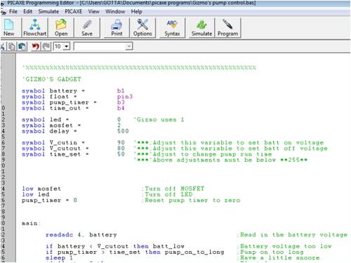
That�s it! - Chips and your away. I have put together a circuit board layout for basic components needed and facilities to access all data pins so other circuitry can be easy added. The artwork is in ExpressPCB format should you want to print it off. ExpressPCB link here 2009-12-30_171906_08M_Prototype_test_board_no_rgb.zip I have posted the board design above for those who wish to copy it and make their own , and will offer a small amount of pre made boards to those who would like to participate from the beginning. If you intend to make your own board than I will ask if you can follow the same pinout connections as I have used. Ie:- Output 4 for ADC pot, Output 0 � Red led , Output 1 � Blue led, Etc. that way if we all have the same for starters than the code will make sense to everyone and should work correctly for all. It will also make error finding easier for the rest of us to help with. 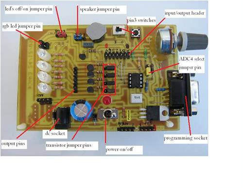
2010-01-02_030603_Parts_list_for_08M_Experimental_Board.pdf 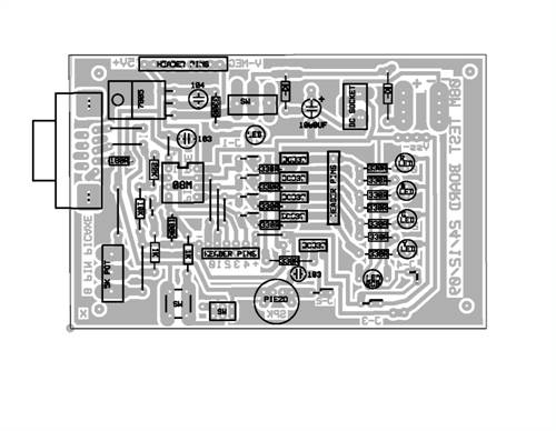
Please note:- Due to the thief of material for this site and reproduction of it for sale. This circuit design and PCB layout remains the property of www.thebackshed.com and may not be reproduced in any manner for sale. It is free for personal use and not permitted for sale without approval from the administrator of thebackshed Or myself the creator. Pete. 
Is anyone interested in participating in this. Pete. Sometimes it just works |
||||
oztules Guru Joined: 26/07/2007 Location: AustraliaPosts: 1686 |
I have avoided the damn things as long as possible.... but I guess it's time to succumb to them..... count me in. ......kicking and screaming ..........oztules Village idiot...or... just another hack out of his depth |
||||
| Downwind Guru Joined: 09/09/2009 Location: AustraliaPosts: 2333 |
Good to have you aboard Oz. Just need a few more to crawl out of the wormwood ... kicking and screaming. Pete. Sometimes it just works |
||||
| Downwind Guru Joined: 09/09/2009 Location: AustraliaPosts: 2333 |
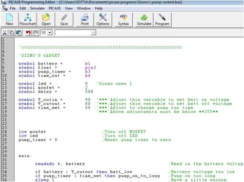
Above is a screen shot of the main window in programming editor. It is a easy package to use with the Picaxe and it uses colour for the text to indicate what the commands and instructions relate to. For instance all the text shown in Green is not a part of the program and is only there for human use as a comment description of what the program is about. Any text after a ( � ) will be in green and ignored by the program. This is handy to remember should you want to remove a section of program temporarily than comment it out, by placing a ( � ) in front of the line of code. This is much easier than deleting and retyping it later. ( less chance of errors) In programming editor under Help there is all the information needed. The section Basic Commands is all the information and how to use the commands. It is well worth printing this off but is over a hundred pages so print back to back if you do. You will need to reference this information frequently to understand the commands you need to use to preform a task. It looks complicated but will make sense when you get to use it. I will try a little waffle to see if I can explain a few things a bit clearer. There is many ways and formats of constructing a program and the way you choose is up to yourself. My preferred method is to keep the program format as close to English as possible so you can read down the program and it makes some sense. To be able to do this we need to use Symbols a symbol is just a way of giving a name or title to something. This is important when we have long programs or they get very messy and confusing fast. In the example above - Symbol Battery = b1 � This gives the Variable b1 the name Battery so we can now use the word battery in our program instead of b1, to keep the program reading in English. (you can still use b1 if wanted and will do the same) There is some English words reserved for the picaxe instructions and can not be used as symbols, like- switch, pause, count, button, input, etc etc. There can not be spaces in a word used as a symbol like , time out , so for this we use an underscore to join the 2 words like , time_out . There is many other advantages to using symbols like above symbol time_set = 50 we have given time_set the value of 50 and every line used in the program after that has time_set used in it, is = 50. Lets say we used it 10 times throughout the program and we want to change the value of 50 to 100 then we only need to change the 50 up the top in the symbols = 50 and all 10 times in the program will change to 100 rather than going through the program and changing each line separately. A symbol can be used to name a pin out as above Symbol mosfet = 2 This has called output pin 2 Mosfet so when the program reads � high mosfet � we know it is the mosfet we are switching on and not the led or something else. We could just say high 2 and this will do the same but after several lines it gets messy with what the $#@% high 2 was. It is important to have a look at the pin diagram for the picaxe in use, 08M in this case. You will see that the pin numbers given is not the same as the physical IC pins themselves. It is the pin numbers given that we use in the program. Many of the pins on the micro will perform several tasks. For instance pin-2 can be an input, an output, an ADC input, PWM output, and Tune (music). Where as pin-3 is only a digital input. It is just a matter of how we address these pin in the program to how they operate. For instance if we say � high 2 -- then pin-2 will be an output. Should we say � if pin2 = high then ��.. it will be an input. Clear as mud Ha!! VARIABLES A variable is just a memory location that we put data into. There is 14 of these locations B0, B1, B2,����B13. These are work registers and all data in them will be lost when power is switched off. If we read data into the micro or create data within, than we need to put the data somewhere that it can be found and accessed. This is what we use variables for. They can be used in any order and can store a value from 0 to 255. Larger values can be stored in Word variables W0,W1,���W6 but lets not go there yet. Above we used variable B1 for Battery and in the first line of program under Main it is told to read the ADC input of pin 4 and put the value of the data into B1 or Battery. ( readadc 4, battery ) Now we can use this data elsewhere as is done in the second line of program. If Battery < V_cutin then batt_low. If battery value is less than 90 then goto batt_low. ( batt_low is just another section of the program that it is directed straight to if the condition is true.) The value in B1 (battery) will be over written on the next pass through the program when it is told to � readadc 4, battery. A few other simple but needed instructions are, a Label at the start of the main program. Above I used MAIN but can be anything. A label MUST have ( : ) proceeding it --- Main: The bottom of the program should have a GOTO statement to tell it where to go next or it will just fall through into abyss. It is a good practice to always place a Goto Main statement at the end of every program regardless. This way when it gets to the bottom it is instructed to loop back to the top and start over again. The program is not case sensitive and will read main the same as MAIN or Main. Enough for now!!! Pete. Sometimes it just works |
||||
| vasi Guru Joined: 23/03/2007 Location: RomaniaPosts: 1697 |
Great initiative Downwind, And I liked the board, I wanted to make my own but your design is very good, thank you for sharing it! Vasi Hobbit name: Togo Toadfoot of Frogmorton Elvish name: Mablung Miriel Beyound Arduino Lang |
||||
| Tinker Guru Joined: 07/11/2007 Location: AustraliaPosts: 1904 |
Hi Pete. I would like to try this if you have a spare ready made PCB left for me. Assembling a board is no problem, etching one is... Let me know how to obtain one and what kind of payment you prefer - cheque is easiest this end. I also found a USB to serial cable (9pin) with the associated CD for my old laptop so I assume this will do for the Picaxe. One thing in your detailed information above puzzles me though, there are lots of black squares on edge with a ? embedded liberally sprinkled amongst the text. What does this stand for? I use Windows Vista and assume its some sort of code problem? Klaus |
||||
| Downwind Guru Joined: 09/09/2009 Location: AustraliaPosts: 2333 |
Hi Klaus, Are you sure its not your eyes with the New Year cheer? Looking at the text this end i do not see what you mean.( than i wrote it so any thing is possiable ) There is no enbeded code in the text that i am aware of. I also use Vista so am a little miffed on this? and will wait to see if others comment the same. Now to more serious matters. I would be good to have you aboard and participate in this. There is a board here with your name on it. A cheque is fine as its not a huge exspence and i know where to find you. (here) I will PM you and discuss payment and postage details off forum. Happy New Year to you and all and may it be a picaxe year to boot for 11111011010. Pete. Sometimes it just works |
||||
| cobo351 Newbie Joined: 18/12/2009 Location: United StatesPosts: 34 |
Hi Pete, your timing for teaching us about the Picaxe is perfect. I just bought a Coleman Air controller and learned that it uses a 08M than started reading about them. I also stared reading about the Picaxe Logger project on this site which I would like to try to build. However I need to learn the basics first I am very interested in getting a spare board from you please pm me to let me know how to pay you for it and the shipping. Thank you for being willing to spread you knowage to others, and have good timing. Cory |
||||
| vasi Guru Joined: 23/03/2007 Location: RomaniaPosts: 1697 |
Hi Downwind, This is what I see from Firefox under openSUSE Linux 11.2: 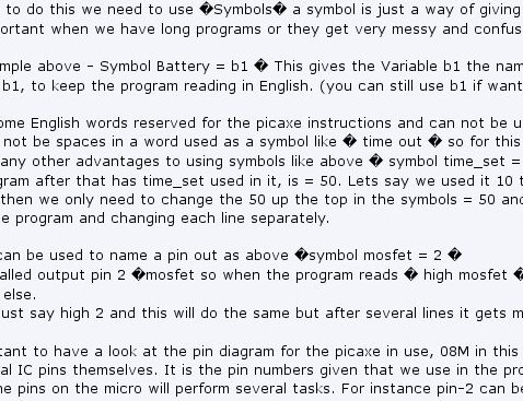
maybe you should use a normal " instead of � Vasi ----------------------- Edit: Ah you are using that character for comments... (') this one between brackets... Hobbit name: Togo Toadfoot of Frogmorton Elvish name: Mablung Miriel Beyound Arduino Lang |
||||
| Downwind Guru Joined: 09/09/2009 Location: AustraliaPosts: 2333 |
Hi cobo351 What the $#%& is a coleman air controller? The picaxe is a expencive slow chip by comparison to other micros and would think they might have used a PIC that is the same part number as a 08m without the boot loader program built in. Otherwise a blank picaxe and not the same thing. You pay dearly for the boot loaded picaxe compared to the blank pic. And NO you cant make a pic into a picaxe. Then again i could well be wrong and it might be a 08m used in the coleman. Its good to have your interest in this thread and i will PM you soon regarding the board. Pete. Sometimes it just works |
||||
| Downwind Guru Joined: 09/09/2009 Location: AustraliaPosts: 2333 |
Thanks Vasi, I see now! It dont look like that when i log on in IE. It was writen in Winword and i only used normal inverted commers and brackets which is what the square blocks are. Sorry for this but was unaware of how Firefox and other operating systems would be effected by " and ( ). Tinker, Your eyesight is fine and it was not the N.Y. cheer. Thats the first lesson learnt for the new year. Hmmm whats next?? Pete. Sometimes it just works |
||||
| oztules Guru Joined: 26/07/2007 Location: AustraliaPosts: 1686 |
running opera in linux here..... no problem with the things Tinker and Vasi are seeing.... maybe it's firefox? .........oztules Village idiot...or... just another hack out of his depth |
||||
| Gizmo Admin Group Joined: 05/06/2004 Location: AustraliaPosts: 5185 |
Hey Oz, if you ever want to upgrade I have a old copy of Windows 95 you can have.  The best time to plant a tree was twenty years ago, the second best time is right now. JAQ |
||||
| Downwind Guru Joined: 09/09/2009 Location: AustraliaPosts: 2333 |
I have tried viewing the text in both Firefox and IE and dont get the squares some of you do. Its a bit hard to fix when the problem dont show up my end. I edited all the inverted commars out so let me know what else i need to change. Pete. Ps. I liked win 95  but must look forward and not back. but must look forward and not back.Sometimes it just works |
||||
| Downwind Guru Joined: 09/09/2009 Location: AustraliaPosts: 2333 |
Tinker, I have not used a usb to serial cable, but see there is a driver download for XP and Vista on the microchip site down the bottom of the page programming editor is downloaded from. You might need this driver. I dont know. It looks like programming editor is supported for Mac and Linux uses. Have a look down the page at microchip as there is several downloads referring to these. Pete. Sometimes it just works |
||||
| VK4AYQ Guru Joined: 02/12/2009 Location: AustraliaPosts: 2539 |
Hi Pete Count me in on this one but keep it simple as I think someone has taken a picaxe to my brain and turned it to mush. All the best Bob Foolin Around |
||||
| cobo351 Newbie Joined: 18/12/2009 Location: United StatesPosts: 34 |
Downwind, the Coleman air controller is a charge controller I bought on eBay on the auctions for them it says thay have a picaxe 08m chip even has a link to download the picaxe software. Which is how I first learned about the picaxe. It has a RJ-11 serial port can I use the same port on the learner board? And can it be used with a USB port on my laptop? |
||||
| Downwind Guru Joined: 09/09/2009 Location: AustraliaPosts: 2333 |
cobo351 The good part is they have given the software as you can not download the software from a picaxe only upload to it many times. As for the port questions. All picaxes use a 3 wire connection to serial unless they have dedicated usb built in as some do. The budget end 08m etc do not. There is a usb to serial converter cable avaliable and i have not used one as yet. From what i have read they should work fine with the correct driver and as i mensioned else where, Microchip lists a driver download for this cable. You might need to make a crossover adapter from D9 serial plug to RJ-11 that should not be to hard with only 3 wires. Or just program the chip in the learned board and swap it over to the coleman. Once programmed they can be removed and plugged into any applicable circuit and will preform the programmed task for ever and a day until reprogrammed to do something else. I would however keep the original chip with its program as is, and play with a new chip for any changes you wish to make. Then if you get it wrong you can always plug the original back in. Each time a change is made the whole program gets rewrittn to the chip not just the changes. You sound eager to want to have a fiddle. Pete. Ps. do you have a link to the software as i would not mind a look at the code. Sometimes it just works |
||||
| Janne Senior Member Joined: 20/06/2008 Location: FinlandPosts: 121 |
Hello, The idea behind this thread is great. The picaxe should be easy enough to get started, and give encouraging results right from the beginning. 
About the usb-to-serial converters, I've tried 2 different models and both worked. The "official" usb download cable from the manufacturer is propably the easiest way to go(in fact, it's just an usb to serial converter built right into the usb plug). It can be found from the manufacturer with a code of AXE027. BTW, it's rev-ed that makes the picaxe, microchip just produces the pic chips the picaxe is based on.. Just to clear any confusions. The homepage of the picaxe can be found at http://www.rev-ed.co.uk/picaxe/ I'll also be sticking around this thread, there's always new things to be learnt  If at first you don't succeed, try again. My projects |
||||
| VK4AYQ Guru Joined: 02/12/2009 Location: AustraliaPosts: 2539 |
Hi Pete I read the page on programming and understood the first bit a bit, but got lost in the second bit which for me isnt unusal, just a suggestion to make it a bit easier for dummies like me, could you leave a larger space between the command and other text: bat1 is bat 1 reffering to Battery, sorry to be pedantic but when the text runs tobether I get lost or more loster. Keep up the goodwork Bob Foolin Around |
||||
| Page 1 of 5 |
|||||
| The Back Shed's forum code is written, and hosted, in Australia. | © JAQ Software 2026 |
