
|
|
Forum Index : Electronics : Bubblejet to uv led pcb scanner
| Page 1 of 2 |
|||||
| Author | Message | ||||
Downwind Guru Joined: 09/09/2009 Location: AustraliaPosts: 2333 |
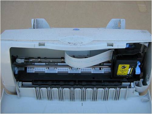
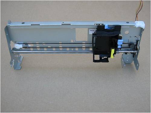
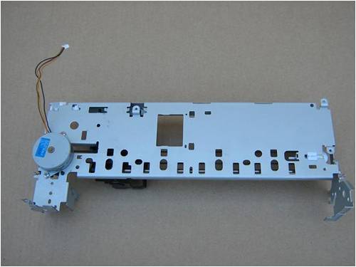
To follow on from a topic started in another thread, This is what i have used to make a uv led scanner for making printed circuit boards. I know there is a few other ways shown on the forum here that used a converted flatbed scanner etc. When i came to build mine the junk pile yeilded a old epson c61 bubblejet printer that was used as it was there. I have since built several more from various other printers.( Mainly Canon ) A discarded Canon BJC 1000SP was gutted below in the photos to show the basic bits required to construct a scanner from. There is about 6 screws to remove the disassemble a printer to the bare bones carriage mechanisim needed. The epson is a better choice as the carriage is slightly longer and it uses a dc motor compared to a stepper motor as used in most printers. Any will work but setting up the driver circuit for a stepper is a little harder than the dc motor. 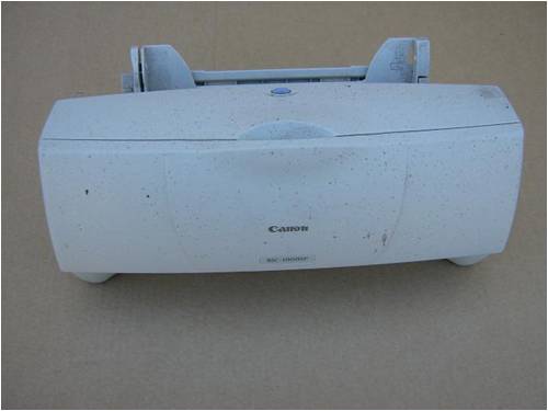
The one i built is nothing to pretty but works well and has given consistant results and trouble free operation. 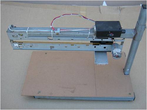
When time permits i will tidy the circuit board artwork up for the dc motor and the stepper motor as well and post that to should anyone else wish to copy it. Pete. Sometimes it just works |
||||
| VK4AYQ Guru Joined: 02/12/2009 Location: AustraliaPosts: 2539 |
Hi Pete Looks good to me, my wife has one of these thats not used any more so shal pirate it at first oppertunity. Will a picaxe run one of these units? Bob Foolin Around |
||||
| Gizmo Admin Group Joined: 05/06/2004 Location: AustraliaPosts: 5185 |
Bugger, I threw away a BJ1000 just a few weeks ago! 
I did rip the motors and circuit boards out to add to the spare parts pile though. Glenn The best time to plant a tree was twenty years ago, the second best time is right now. JAQ |
||||
| Downwind Guru Joined: 09/09/2009 Location: AustraliaPosts: 2333 |
A picaxe will but it will need to be a 14M or 18X chip to have enough pinouts. A H-bridge or motor driver chip like the L293D ic is required to drive the motor, This will allow for either a dc or stepper motor to operate forwards and backwards. Only a resistor needed between the picaxe pins and the motor driver ic. Its the best thing about using a picaxe as it keeps your component count down, as most functions are done in program with only the need for a few support components. If the printer has not been used for a while than the jet may well be clogged anyways  and you can not get caritages for them anymore and you can not get caritages for them anymore
Pete. Sometimes it just works |
||||
| Downwind Guru Joined: 09/09/2009 Location: AustraliaPosts: 2333 |
The funny thing is Glenn you most likly removed all the bit needed, to remove the bits you kept. 
Any printer will do as there is little difference from one to the other when it comes down to the bare bones of what is used out of them. Pete. Sometimes it just works |
||||
| VK4AYQ Guru Joined: 02/12/2009 Location: AustraliaPosts: 2539 |
Sounds like another application of MURPHY's LAW Bob Foolin Around |
||||
| Downwind Guru Joined: 09/09/2009 Location: AustraliaPosts: 2333 |
Good news. I tested a theory today with using a 08m picaxe and a L293 motor driver chip. ( and yes i did use my 08m test board for it ) The stepper motor can be controlled from a 08m and a L293 driver chip. It will only allow for full stepping but that wont matter in this application. Full steps make the carriage "chug" up and back at low speed, but who cares. Motor voltage used is 12 volt. The draw back is, with a 08m it only leaves input3 on the picaxe free for limit switches if used. Or the distance of travel can be set in program with the number of step in each direction. The speed of travel will also need to be set in program to, but there is little need to want to adjust speed as you want the same exposure time per board anyways. The other draw back is it leaves no output pin on the 08m to switch the leds off with after the set number of passes. This could be done using a limit switch. Would mean the leds would go off when the switch was closed at the end of every pass but should not matter as it pays to start with the leds not over the pcb and let them travel across the pcb and then return. I now need to put a schematic together and redo the circuit board artwork to use a 08m instead of a 18x. The program is a little trickier but now that is written its just a matter of changing a few values for setting speed, number of steps, and number of passes. 3 values up the top of the program to change. Think you should be able to handle that Bob. Pete. Sometimes it just works |
||||
| VK4AYQ Guru Joined: 02/12/2009 Location: AustraliaPosts: 2539 |
Hi Pete I think I can Pete just got back to it now as the solar guys where here today and fitted a earth leakage relay and I have been havinh fun all afternoon trying to get things working again no luck came to the conclusion the relay is faulty. Got the printer stripped and reassembled this morning was a 210 not a 1000 is that going to be a proble3m 4 wire moter so must be a stepper and seperate 12v 1 amp power supply. Just an idea how about using a reed switch to control led so switch of at either end or one end only to give you another output on Mr. Pic. All the best Bob Foolin Around |
||||
| Downwind Guru Joined: 09/09/2009 Location: AustraliaPosts: 2333 |
Basically there the same throughout the range just different housing and different printer head which neither of we use anyhow. It will be fine. 4 wire stepper (Bipolar)is standard in them. I used a reed switch attached to the moving carriage for a travel limit so i could slide a bar magnet along the support frame and set the max distance travelled, as when doing a small board it takes a lot of time to scan a distance where there is no pcb to expose. Its just a matter of time to complete the scanning process. As you start the process then walk away and come back when its finished, no need to sit and watch. I will take some photos tomorrow of setting up the travelling carriage (old printer head) to mount the uv leds from. Im halfway through the pcb artwork for the 08m and L293 motor driver board. Guess i better make one to check if its all correct before posting the circuit. You will need to construct some sort of mount to support the whole carriage arm above the pcb being exposed. It is best if the height of the leds to pcb can be adjusted up and down to get a uniform coverage of light without huge overlaps or low coverage areas of uv light. Once position is found it wont need to be adjusted again. I made the whole carriage arm moveable up and down. Its a matter of what you have to work with, to how you go about it. Wood or steel. Pete. Sometimes it just works |
||||
| VK4AYQ Guru Joined: 02/12/2009 Location: AustraliaPosts: 2539 |
Hi Pete Looking at your photos the height id about 5" above the platten is this height critical? I am thinking about using wood as I have plenty if, at afixed height I could use spacers to raise the board being exposed, this way I could make a top for a dust cover as that is a bit of a problem here. All the best Bob Foolin Around |
||||
| Downwind Guru Joined: 09/09/2009 Location: AustraliaPosts: 2333 |
5" is somewhere around the mark but will depend on the lens in the led used and the height will need to be adjusted to suit them. Can you pop rivet a light section of angle onto the end of the carriage arm so you can screw it to the vertical mount later when the correct height is found. Then a square of chipboard for a base with a vertical block screwed to it for a mount to fix the carriage arm to, would about do it. Best not to use spacers under the pcb as this allows for problems if spacers are forgotten. Get it right once and no need to adjust again. Its just a matter of having the leds switched on and lift the arm up and down, to a even light patten is found and fix the arm at that height. The end. There is only the weight of the arm and the leds to support not a lot. As for dust its not a huge problem as long as you wipe the dust off the cover glass and keep it off the pcb the rest wont matter much. Pete. Sometimes it just works |
||||
| VK4AYQ Guru Joined: 02/12/2009 Location: AustraliaPosts: 2539 |
Hi Pete I see what you mean about the focal length of the leds so will leave that till I make the array. I will concentrate on the programming for now. All the best Bob Foolin Around |
||||
| Downwind Guru Joined: 09/09/2009 Location: AustraliaPosts: 2333 |
The good news is the driver board is built and tested and works well 
The program is done and working. This program is to operate a bipolar stepper motor used in a bubblejet printer for driving the carriage up and back. The function of the program is to travel a set number of steps and then return the same amount of steps. This is equal to 2 passes, one forward and one back. The number of steps is set in the program under �. Steps�� The number of passes is set in the program under �Symbol Passes� The speed of travel is set in program under � Symbol Speed��� The minimum speed value that can be set is 10 being the fastest speed and the higher the value above 10 the slower the travel. Ie :- 1000 is real slow. At the start of a cycle the carriage will step forward 10 steps, then start the step count from there. This is to move the carriage off the limit switch to turn the UV Led�s on. At the end of the cycle the carriage will step back 10 steps to hit the limit switch and turn the Led�s off. With the carriage travelling in the forward direction a push switch connected to pin3 can be pressed at a selected travelled distance and the limit of travel will be set to this point and the carriage will reverse. A reed switch and magnet can also be used for this purpose. Once the cycle has completed and the carriage has parked all driver inputs are switched to low. If the push switch connected to pin3 is then pressed the cycle will repeat. At the start of each cycle the number of steps or travel distance will be reset back to full distance. The program frequency is set to 8 Megs as this gives a smoother stepping. It can be run a 4 Megs if preferred . If the stepper motor runs in the wrong direction at start up, reverse the wires to 1 coil. [code] '%%%%%%%%%%%%%%%%%%%%%%%%%%%%%%%%%%%%%%%%%%%%%%%%%%%%%%%% 'Picaxe 08M and L293B stepper motor driver for UV scanner 'By Downwind 16/01/2010 # picaxe 08m symbol step_counter = w0 symbol marker = b2 symbol flag = b3 symbol y = b4 symbol speed = b5 symbol passes = b6 symbol pass_counter = b7 symbol steps = w6 marker = 1 if pin3 = 0 then 'Fast speed test mode speed = 10 goto start endif goto main setup: '%%%%%%%%% SET SPEED HERE ..10 minimum %%%%%%%%%%%%%% speed = 250 '%%%%%%%%%%%%%%%%%%%%%%%%%%%%%%%%%%%%%%%%%%%%%%%%%%%% start: '%%%%%%%%%%% SET NUMBER OF PASSES HERE %%%%%%%%%%%%%% ' passes = 10 '%%%%%%%%%%%%%%%%%%%%%%%%%%%%%%%%%%%%%%%%%%%%%%%%%%%% '%%%%%%% SET NUMBER OF STEPS HERE (one way)%%%%%%%%%% steps = 550 '%%%%%%%%%%%%%%%%%%%%%%%%%%%%%%%%%%%%%%%%%%%%%%%%%%%% flag = 1 step_counter = 0 pass_counter = 0 marker = 0 y = 0 high 0,1 low 2,4 setfreq m8 ' set frequency t0 8 megs gosub step_10 main: ' Start of program '%%%%%% WAITS AT END & START OF CYCLE FOR PIN3 BUTTON PRESS %%%% if marker = 1 and pin3 = 0 then setup If marker = 1 then main '%%%%% BACKSTEP 10 STEPS TO TURN LED SWITCH OFF %%%%%%%%% if pass_counter = passes and marker =0 then toggle 0,4 gosub step_10 low 0,1,2,4 marker =1 goto main endif '%%%%%% FORWARD STEPPING %%%%%%%%%%%%%%%%%%%%%%%%%%%%%%%% if step_counter => steps and flag = 1 then step_counter = 0 inc Pass_counter toggle 0,4 flag = 0 pause speed endif '%%%%%%%%% REVERSE STEPPING %%%%%%%%%%%%%%%%%%%%%%%%%%%%% if step_counter => steps and flag =0 then step_counter = 0 inc pass_counter toggle 0,4 toggle 1,2 flag = 1 pause speed endif '%%%%%%%% MAIN STEPPING ROUTINE, 1 step each coil %%%%%%% toggle 1,2 toggle 0,4 inc step_counter pause speed toggle 0,4 inc step_counter Pause speed '%%%%%% ADJUST TRAVEL DISTANCE IN STEPS %%%%%%%%%%%%%%%%% if pin3 = 0 and step_counter > 50 and flag = 1 then steps = step_counter goto main endif goto main '%%% MOVES CARRIAGE 10 STEPS AT START AND END OF CYCLE %%% step_10: For y = 0 to 6 toggle 1,2 toggle 0,4 pause speed toggle 0,4 Pause speed next y return goto main '%%%%%%%%%%%%%%%%%%%%%%% THE END %%%%%%%%%%%%%%%%%%%%%%%%% [/code] Just need to do the schematic and then will post the artwork with it. Pete. Edit of code 17/01/2010 Sometimes it just works |
||||
| Downwind Guru Joined: 09/09/2009 Location: AustraliaPosts: 2333 |
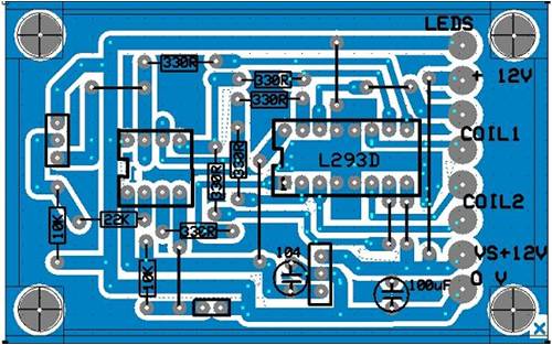
Here is all the files for the PCB artwork (in Expresspcb) circuit schematic as well as a zip file of the program code. 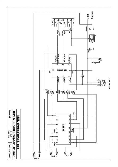
2010-01-17_145235_08M_&_L293B_stepper_driver_schematic.pdf 2010-01-17_145359_PCB_artwork_STEPPER_08M_with-293d_chip.zip 2010-01-26_202158_08m_Picaxe_Stepper_Driver_Code.zip 2010-01-17_152848_08M_and_L293_Stepper_Driver_Parts_List.pdf The programming socket allowed on the circuit board is 3 header pins to save on space and easy mounting into an enclosure. A adaptor cable will need to be made from a 9 pin D female socket with 3 wires to a 3 pin header socket to program chip on board or the chip removed and programmed in a different board and reinserted into the driver board afterwards. Pete. Edit code file 17/01/2010 Sometimes it just works |
||||
| Downwind Guru Joined: 09/09/2009 Location: AustraliaPosts: 2333 |
I went to get some L293B motor driver chips today and got a rude shock on the price of each chip. $5.00 each. The one i used for the test board was a chip from my parts draw and did not remember the price of it. (Pete, soon put back the stick of 20 chips and settled for 5 only) All be it, there is not a lot of options other than building 2 x H bridges and that would likely cost more than the L293B chip and be a pain to construct. For a small board with 2 chips it gets costly fast at $12.00 for the 2 chips. Electronics can be a exspensive hobby. Pete. Sometimes it just works |
||||
| Downwind Guru Joined: 09/09/2009 Location: AustraliaPosts: 2333 |
*****PCB OFFER****** In the next few days i will be making some PCB's of the above stepper motor driver board if anyone is interested in a board then let me know....Soon. A extra board or two i dont mind but will not be an ongoing offer. The board will run any small bipolar (4 wire) stepper motor and the driver chip is rated to 1 amp max per channel. Although the L293B chip would run rather hot at 1 amp i would think. Pete. Sometimes it just works |
||||
| Downwind Guru Joined: 09/09/2009 Location: AustraliaPosts: 2333 |
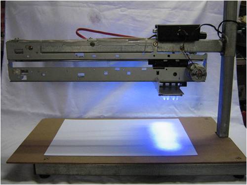
UV LED SCANNER OPERATION 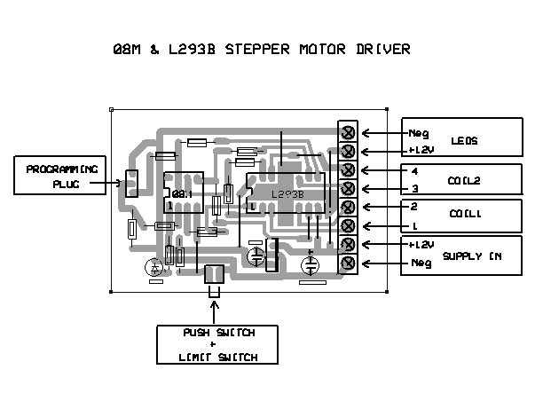
The push switch / limit switch header pin connection can preform several functions. 1. A push switch attached to 2 pins is mounted in the top of the box, this is used to start the travel/scan cycle. 2. If pressed again when the carriage is moving in a forward direction it will set the position of distance travelled as the limit position and the carriage will return. 3. If a reed switch or micro switch is connected to the remaining set of header pins, this than can be used as a limit switch to set a maximum travel distance. This is not necessarily required as the maximum amount of steps to travel full distance of the rail is set in program. 4. If the push switch is held down when switching the toggle switch on, the program will enter a test mode where the carriage will move at a fast rate for the next cycle of passes. (then return to program set speed next cycle) A bipolar motor normally has 4 wires, which is connected to 2 sets of coils. A multimeter is needed to test the ohms resistance between the 4 wires to determine the matching pairs of wires for each coil. A ohms reading will only be achieved with the 2 wires to a particular coil. It don�t matter which pair of coil wires is connected to terminals 1 & 2 with the other pair of coil wires connected to terminals 3 & 4. If the motor goes in the wrong direction at start up, then reverse 1 set of coil wires only. Now the carriage should advance down the rail at start up when button is pressed. The SPEED of travel is set in program and presently set to 250. The higher the number used the slower the travel speed. 250 gives about 200mm of travel per minute on the carriage I used. I find this is a good speed for 8-10 passes over the board for exposure. Number of PASSES is set in program and presently set to 10. The passes should always be set in even numbers so the carriage always returns to the rest position to switch the leds off. The number of STEPS for full travel distance of the rail is set in program and presently set to 550. 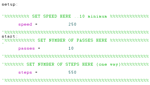
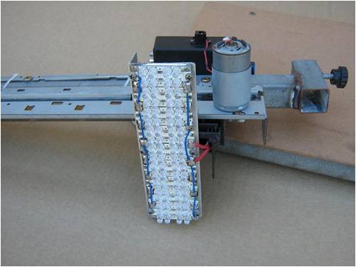
The supply voltage can be 12-24 volts but the supply voltage is not regulated to the UV Leds and must be kept within the led setup operating voltage. A 12volt DC, 1 amp, Plug pac should be adequate. The height of the UV leds off the board must be set so the spot of light from each led slightly overlaps the other, so to ensure even exposure across the circuit board. Mine is set to around 120mm from base board to the leds. At the start of each cycle the carriage will step 7 steps forward and start from there. This is to switch the leds on. At the end of the cycle the carriage will step back 7 steps and switch the leds off, then rest in that position until the start switch is pressed again. If the UV leds are on when power is switched on at the toggle switch, than push the carriage back until uv leds are off, before starting the cycle. The carriage with unused metal bits trimmed off with tin snips 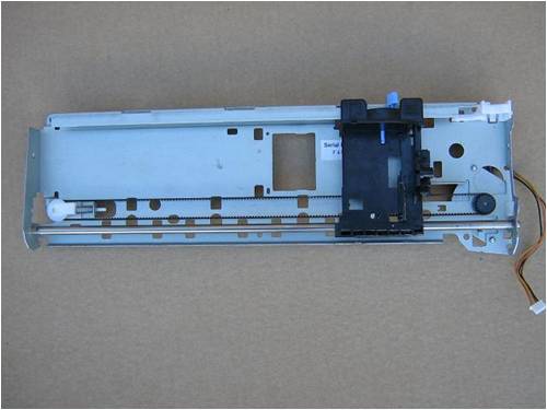
Carriage with printer head removed and excess plastic bits cut off. 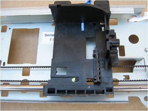
A 3mm flat spacer was placed on the carriage and a piece of aluminium Angle was cut and pop riveted onto the carriage as a mount for the UV leds to attach to. 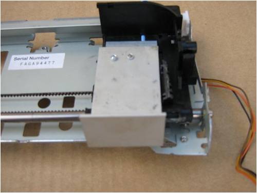
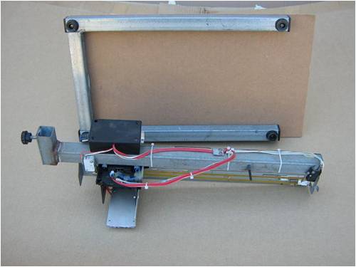
A piece of aluminium flat 3mm x 40mm x 150mm was attached to the chassis for a mounting point to be screwed to a vertical support. A section of 30mm x 300mm x 100mm of aluminium angle was also attached as a mount for the controller box. The control box was stuck on with some double sided adhesive Velcro. 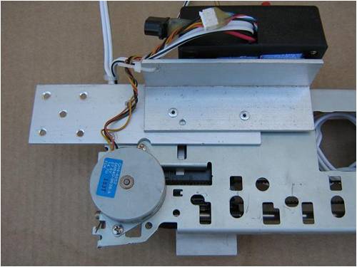
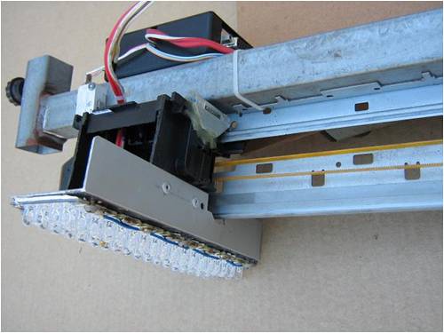
A micro switch was fitted to the end of the chassis so the carriage would activate the switch. The UV leds are wired through the micro switch to enable them to be switched on when the carriage moves away and switched off again when the carriage comes to rest at the end of the cycle 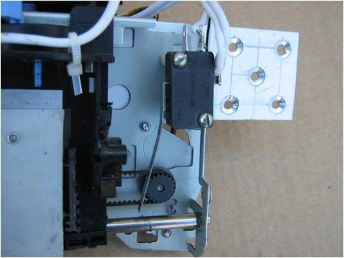
Showing the micro switch activated by the carriage and the mounting point for the chassis 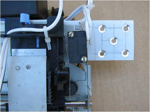
2 metal brackets were used to secure the vertical piece of timber to the base board. The chassis assembly was then attached to the vertical support. 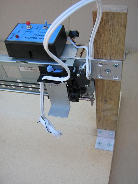
A view of the rear when all is attached 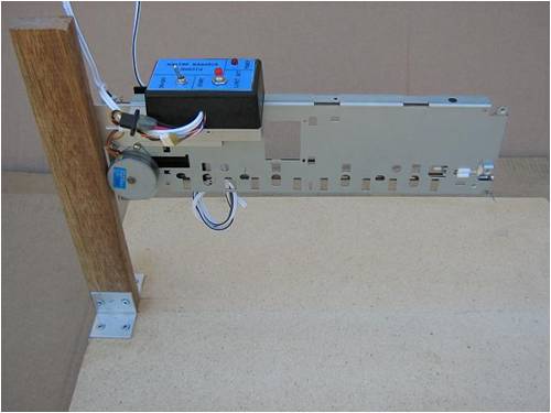
Enough slack needs to be left in the UV led cable to allow full travel. A length of twin conductor cable was used that was flexible enough to handle the bending movement of the cable as the carriage travelled forwards and backwards. 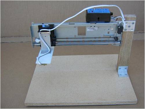
2 rows of UV leds attached to the carriage and wired in. 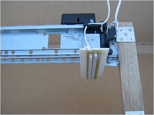
Pete. Sometimes it just works |
||||
| VK4AYQ Guru Joined: 02/12/2009 Location: AustraliaPosts: 2539 |
Hi Pete That is a realy top job  now I have to get my head around the code to run it. now I have to get my head around the code to run it.
I will send a picture of mine when I put it together. The led array in the picture, is that the one based on your own board or one of the clusters? All the best Bob Foolin Around |
||||
| Downwind Guru Joined: 09/09/2009 Location: AustraliaPosts: 2333 |
The leds are on a board i had made some time ago and have been trying to give it away ever since, as it was configured wrong and need 20 volts to run it. So i cut the tracks and jumper wired it for 12 volt operation and mounted it on this scanner. The led clusters are used in the other one i made that is on the first page of this thread. Pete. Sometimes it just works |
||||
| GWatPE Senior Member Joined: 01/09/2006 Location: AustraliaPosts: 2127 |
Hi Pete, This is a similar project to a digital foam cutting machine I made with a Basic Stamp II. I used D469J quad mosfet drivers, with 4 x stepper motors. I was cutting white, and Blue foam for model plane wings. I used 2 x flatbed scanners, and 2 floppy drives for steppers. The arrangement allowed 2 x X-Y drives on the ends of the cutting wire. This was a rewarding project as well. The Picaxe chips are more versatile now, than the BS-II I worked with. Good to see the final unit. Gordon. become more energy aware |
||||
| Page 1 of 2 |
|||||
| The Back Shed's forum code is written, and hosted, in Australia. | © JAQ Software 2026 |
